Tecnoinox PC70G7A User manual
PC35G7 PC70G7 PC70G7A PC105G7 PC105G7A PCP70G7 PCP105G7 PPC70G7
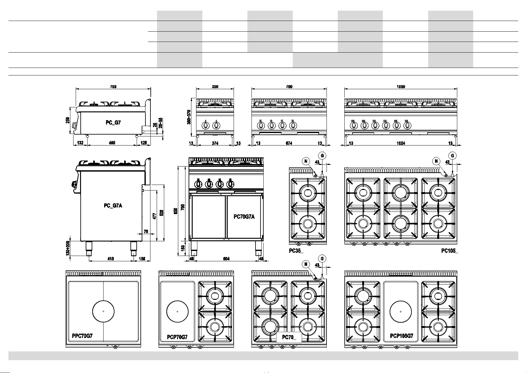
Dimensioni esterne - External dimensions – Außenmaße -
Внешние разм. - Dimensions extérieures - Dimensiones externas.
(mm)
L 350 700 700 1050 1050 700 1050 700
P 700 700 700 700 700 700 700 700
H 280 280 850 280 850 280 280 280
Potenza installata - Installed power – Nennleistung – Установленная
мощность - Puissance installée - Potencia instalada. 10.5kW 19.5kW 30kW 15kW 22.8kW 9kW
G : Attacco gas - Gas inlet connection – Gasanschluss - Вход газа - Arrivée gaz - Entrada gas ( G ½“ EN10226-1 / G ½“ ISO228-1 )
N : Morsetto equipotenziale - Unipotential earthing connection – Potentialausgleich - Эквипотенциальная клеммная коробка - Vis équipotentiel - Tornillo equipotencial
Fig.1 - Abb.1 - рис.1
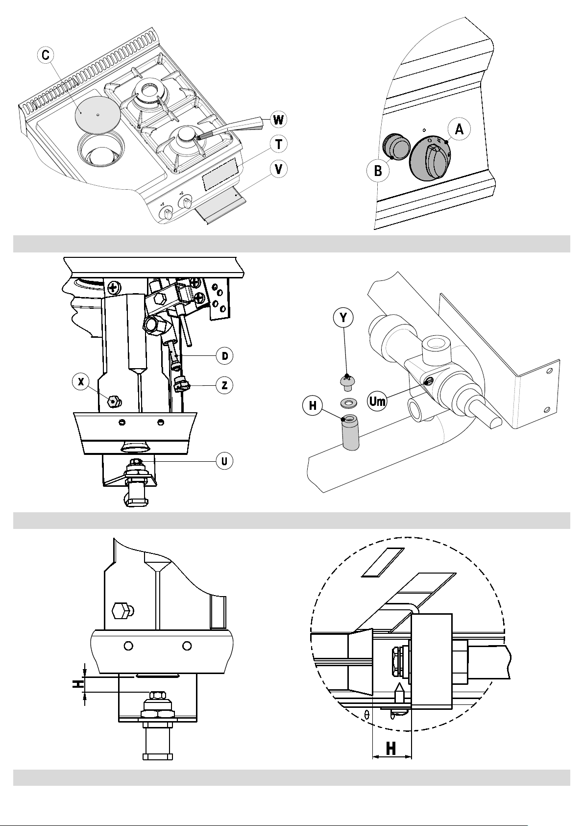
Fig.2 - Abb.2 - рис.2 Fig.3 - Abb.3 - рис.3
Fig.4 - Abb.4 - рис.4 Fig.5 - Abb.5 - рис.5
- PPC70G7 -
Fig.6 - Abb.6 - рис.6
DATI TECNICI - TECHNISCHE DATEN - TECHNICAL DATA - DONNEES TECHNIQUES - DATOS TÉCNICOS 5410.263.00
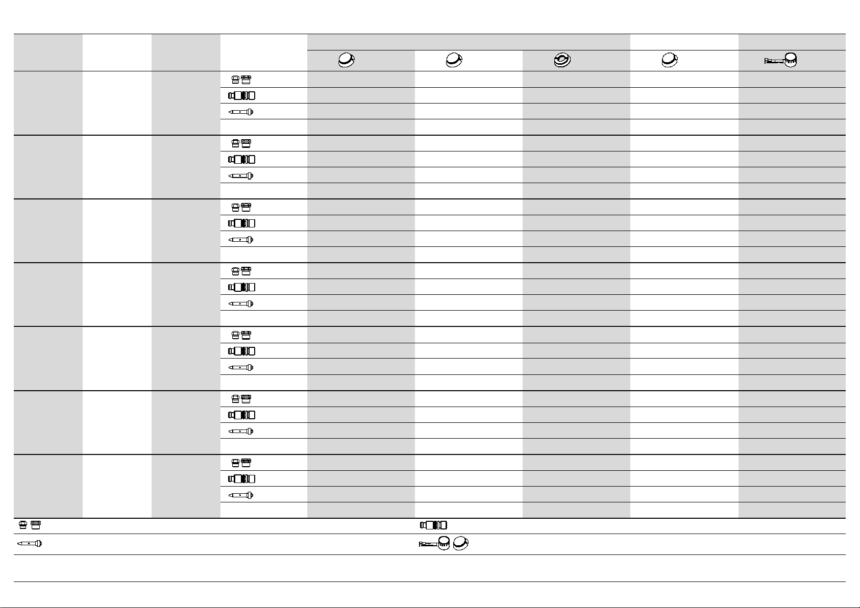
T1. Tabella ugelli – Düsentabelle - Таблица форсунок - Nozzle table - Tableau des injecteurs - Tabla de los inyectores
CATEGORIA
(Kat.;Cat.)P GAS ø 1/100 mm Bruciatore (Brenner, burner, горелка, brûleur, quemador) ½ PIASTRA PIASTRA
3.3 kW 4.5 kW 7.2 kW 4.5 kW 9 kW
2E;2E+;2H 20 mbar G20
MAX 130 155 200 155 220
MIN REG. REG. REG. REG. REG.
PILOTA 35 35 35 35 35
H [mm] 10 14 14 12 11
3+;3B/P+ 28-30/37 mbar G30/G31
MAX 85 105 130 105 140
MIN 55 65 80 65 85
PILOTA 20 20 20 20 25
H [mm] MAX MAX MAX MAX MAX
3B/P 37 mbar G30/G31
MAX 82 100 125 100 135
MIN 50 55 70 55 70
PILOTA 20 20 20 20 25
H [mm] MAX MAX MAX MAX MAX
3B/P 50 mbar G30/G31
MAX 80 90 115 90 130
MIN 50 55 70 55 70
PILOTA 20 20 20 20 25
H [mm] MAX MAX MAX MAX MAX
2LL 20 mbar G25
MAX 150 170 225 170 250
MIN REG. REG. REG. REG. REG.
PILOTA 35 35 35 35 35
H [mm] 9 12 12 10 9
2L 25 mbar G25
MAX 135 165 215 165 240
MIN REG. REG. REG. REG. REG.
PILOTA 35 35 35 35 35
H [mm] 9 12 12 10 9
2S 25 mbar G25.1
MAX 140 165 220 165 240
MIN REG. REG. REG. REG. REG.
PILOTA 35 35 35 35 35
H [mm] 9 10 11 9 9
: Brennerdüse - Burner nozzle - Макс.поз. - Injecteur du brûleur - Inyectores de los quemadores. : Kleinstellschraube - Minimum adjusing screw - Мин.поз. - Vis de réglage minimum - Tornillo de regulación del mínimo
: Zündbrennerdüse - Pilot burner nozzle - Пламя - Injecteur de la veilleuse - Inyectoresdel piloto. : Warmhalteplatte - Heating plate - Плитка - Plaque chauffante - Plancha
H: Aria primaria - Primärluft Abstand -
Первычный
воздух
- Primary air - Air primaire - Aire primario

DATI TECNICI - TECHNISCHE DATEN - TECHNICAL DATA - DONNEES TECHNIQUES - DATOS TÉCNICOS 5410.263.00
Cat. (kat.) P Paese (land - country - pays - país)
I2E 20 mbar LU,PL
I2E+ 20/25 mbar BE
I3+ 28-30/37 mbar BE,LU
I3B/P 28-30 mbar NL,NO,CY,MT
II2E+3+ 20/25, 28-30/37 mbar BE,FR
II2ELL3B/P 20, 50 mbar DE
II2H3+ 20, 28-30/37 mbar ES,GB,GR,IE,IT,PT,SK
II2H3B/P 20, 28-30 mbar BG,DK,EE,FI,LV,LT,CZ,SE,SI
II2H3B/P 20, 50 mbar AT,CH
II2L3B/P 25, 28-30 mbar NL
II2S3B/P 25, 30 mbar HU
II2S3B/P 25, 50 mbar HU
PC35G7 PC70G7 PC105G7 PCP70G7 PCP105G7 PPC70G7
10.5 kW 19.5 kW 30 kW 15 kW 22.8 kW 9 kW
Metano (G20) - (Hi = 9.45 kWh/m3) 1.11 m3/h 2.06 m3/h 3.17 m3/h 1.59 m3/h 2.41 m3/h 0.95 m3/h
Metano (G25 - G25.1) - (Hi = 8.13 kWh/m3) 1.29 m3/h 2.40 m3/h 3.69 m3/h 1.84 m3/h 2.80 m3/h 1.10 m3/h
GPL (G30) - (Hi = 12.68 kWh/kg) 0.83 kg/h 1.54 kg/h 2.37 kg/h 1.82 kg/h 1.79 kg/h 0.71 kg/h
Consumo - Gasverbrauch - Gas consumption - Consommation du gaz - Consumo de gas
IT - 1 5410.263.00
Parte 1 Installazione
PIANI COTTURA GAS
Avvertenze Generali
L'apparecchio descritto nel presente libretto è costruito nel rispetto
dei requisiti delle norme UNI EN 203 eUNI EN 437.
Quest’apparecchiatura è concepita unicamente per la cottura degli
alimenti, ogni altro tipo d’impiego è da ritenersi improprio; è destinata
solo ad uso professionale da parte di personale qualificato.
L'apparecchio deve essere utilizzato esclusivamente sotto
sorveglianza. Si consiglia inoltre un controllo annuale a cura di
professionisti qualificati.
Disattivare l'apparecchiatura in caso di guasto o cattivo
funzionamento.
Si consiglia di installare l’apparecchio sotto ad una cappa aspirante per l’evacuazione dei vapori prodotti durante la cottura.
Prestare attenzione durante il funzionamentopoiché la vasca e le superfici di cottura sono molto calde.
L'allacciamento, l'installazione e la manutenzionedell'apparecchiatura devono essere eseguiti a cura di personale qualificato
secondo le norme e le prescrizioni vigenti nel paese, in conformità alle presenti istruzioni.
Caratteristiche dell’apparecchio
Il presente libretto d’istruzioni per l’installazione ed uso si riferisce ai
piani cottura gas della categoria II2H3+.
La targhetta matricola in poliestere autoadesivo "T"(fig.2) si
trova dietro al pannello portacomandi (all'interno
dell'apparecchio).
Essa contiene i seguenti dati:
Modello: PC35G7 PC70G7 PC105G7
Numero di serie: xxxxxx
Categoria: II2H3+
Anno di fabbricazione: xxxx
Portata termica nominale: 10.5 kW 19.5 kW 30 kW
Tipo di costruzione: A
Base di prova: UNI EN 203-1
Pressione di
collegamento: G30
G20 28-30/37 mbar
20 mbar
Consumo: G30
G20 0.83
1.11
Kg/h
m3/h 1.54
2.06 Kg/h
m3/h 2.36
3.17
Kg/h
m3/h
La targhetta supplementare è in poliestere autoadesivo ed è
applicata vicino alla targhetta matricola, essa contiene tutte le
informazioni sulla predisposizione dell’apparecchio.
Tutte le apparecchiature sono dotate di una rampa per il
collegamento del gas. L’attacco per il collegamento alla rete del gas
"G" (fig.1) corrisponde alle prescrizioni ISO 7/1 e ISO 228/1 (DK) con
attacco ø ½”, esso è situato nella parte inferiore della macchina.
Modello N° bruciatori Tipo
PC35G7 2 Fornello
PC70G7 4 Fornello
PC105G7 6 Fornello
PCP70G7 2+1 Fornello + Piastra
PCP105G7 4+1 Fornello + Piastra
PPC70G7 1 Piastra
La struttura dell’apparecchio è d’acciaio inox, i bruciatori sono in
ghisa e in acciaio inox quello del forno. Tutti i modelli sono dotati di
piedini regolabili in altezza.
La conduttura principale del gas è in acciaio zincato. Le condutture di
collegamento dal rubinetto al bruciatore sono in rame.
ATTENZIONE!
Interporre tra l'apparecchio e la rete di distribuzione gas un
rubinetto d’intercettazione.
Collegamento alla rete
Prima di procedere all’installazione dell’apparecchiatura
è indispensabile farsi rilasciare dall’ente erogatore del
gas il nullaosta all’installazione, raffrontare poi i dati
relativi alla predisposizioni dell’apparecchiatura
(targhetta caratteristiche) con l’erogazione in loco.
Togliere l'imballo dall'apparecchiatura, rimuovere la pellicola
protettiva e, se necessario, eliminare le tracce di colla con l'ausilio di
un idoneo solvente. Si raccomanda di smaltire l'imballo secondo le
norme vigenti (per maggiori dettagli fare riferimento al capitolo
"ECOLOGIA E AMBIENTE”).
Prima di collegare l’apparecchio alla rete del gas controllare sulla
targhetta matricola che l’apparecchio sia predisposto e collaudato
per il tipo di gas erogato. Qualora il tipo di gas riportato in targhetta
non corrispondesse al tipo di gas erogato e alla pressione
disponibile, consultare il paragrafo “TRASFORMAZIONE ED
ADATTAMENTO”.
Il collegamento alla rete di distribuzione del gas deve avvenire con
tubi metallici, di diametro adeguato e con interposizione di un
rubinetto d’intercettazione omologato. Se vengono impiegati tubi
flessibili, questi devono essere di acciaio inossidabile secondo le
norme vigenti. Durante l'installazione sono da osservare e rispettare
tutte le norme vigenti quali:
■Norma di sicurezza UNI-CIG 8723, legge nr.46 del 5 marzo 1990
e circolare nr.68.
■Norme regionali e/o locali quali regolamento edilizio.
■Norme antinfortunistiche vigenti.
■Prescrizioni antincendio.
■Relative norme CEI.
Si consiglia d’installare l'apparecchio in un ambiente ben areato e
sotto una cappa aspirante per l'evacuazione dei fumi e vapori
prodotti durante la cottura.
L’apparecchio può essere installato da solo o in batteria.
Rispettare la distanza minima di 80mm tra apparecchiatura ed
eventuali pareti in materiale infiammabile, divisori, mobili da cucina o
apparecchiature adiacenti.
Le superfici a contatto con l’apparecchiatura dovranno essere
rivestite in materiale isolante termico di tipo non combustibile.

IT - 2 5410.263.00
L’apparecchiatura non deve essere sistemata vicino a fonti di calore,
l’ambiente circostante l’apparecchiatura non deve superare la
temperatura di 50°C.
Ad installazione avvenuta procedere al controllo di tenuta dei
raccordi. Per individuare eventuali perdite si consiglia l’utilizzo di
prodotti a base schiumosa non corrosiva, tipo spray cerca fughe.
Durante la prova di tenuta non usare fiamme libere!
Il costruttore non si assume nessun impegno di garanzia per danni che accadessero a causa dell’inosservanza delle istruzioni
d’installazione d’uso, o d’utilizzo improprio. Non si assume inoltre alcun impegno di garanzia per un allacciamento non
eseguito in conformità alle norme vigenti e le prescrizioni antincendio.
Evacuazione dei gas incombusti
Non è necessario collegare queste apparecchiature ad un camino (tipo di costruzione A1), se ne consiglia però l'installazione sotto cappa aspirante.
Controllo della pressione
La pressione di rete dovrà rispettare quanto segue:
AMMESSO Tra 20/25 e 35/45 mbar
GPL NON AMMESSO Inf. a 20/25 sup. a 35/40 mbar
AMMESSO Tra 17 e 25 mbar
METANO
H NON AMMESSO Inf. a 17 e sup. di 25 mbar
Qualora la pressione di rete sul posto d’installazione non sia come
sopra riportato, avvisare l’ente preposto alla distribuzione e non
procedere alla messa in funzione dell'apparecchiatura prima che la
causa non sia stata individuata ed eliminata.
La pressione di rete è rilevabile attraverso un manometro ad U
(definizione min. 0.1mbar), collegabile alla presa di pressione "H"
(fig.5) dietro il cruscotto.
1. Rimuovere il cruscotto portacomandi.
2. Togliere la vite "Y" e rondella di tenuta (fig.5) dalla presa di
pressione, collegare il manometro.
3. Mettere in funzione l’apparecchio secondo le istruzioni accluse
e controllare se la pressione misurata rientra nel campo delle
pressioni ammesse.
4. Scollegare il manometro e riposizionare vite "Y" e rondella di
tenuta (fig.5) nella presa di pressione.
5. Rimontare il cruscotto porta comandi.
IT - 3 5410.263.00
Parte 2 Trasformazione ed adattamento
Per la trasformazione da un tipo di gas ad un altro, per es. da
metano a GPL, si rende necessaria la sostituzione degli ugelli del
bruciatore principale, del by-pass e del pilota. Tutti gli ugelli sono
contrassegnati da un numero che indica il diametro in 1/100 e forniti
in dotazione in un sacchetto. Dopo ogni trasformazione o
adattamento, sottoporre l’apparecchio ad una prova delle funzioni e
aggiornare la targhetta supplementare in base alla trasformazione o
adattamento effettuato.
Si raccomanda che tutti i lavori relativi all’allacciamento, all’installazione ed alla manutenzione dell’apparecchio siano eseguiti
esclusivamente da personale qualificato ed in osservanza di tutte le relative prescrizioni!
Bruciatore piano cottura – Ugelli e regolazione aria
BRUCIATORE:
1. Sfilare le manopole.
2. Togliere il cruscotto dei comandi svitando le viti di fissaggio
poste sulla parte inferiore, individuare i bruciatori.
3. Sostituire l’ugello “U”(fig.4) con quello adatto al nuovo tipo di
gas vedi “MAX”nella tabella ugelli T1 sezione Dati tecnici.
4. Ripetere l’operazione per tutti i bruciatori.
REGOLAZIONE ARIA:
5. Svitare la vite di fissaggio “X”(fig.4)
6. Regolare l’aria primaria muovendo la boccola fino alla distanza
“H” (fig.6) indicata nella tabella ugelli T1 sezione Dati tecnici.
7. Bloccare a boccola avvitando la vite di fissaggio “X”(fig.4)
PILOTA:
8. Svitare e togliere il dado di chiusura "Z" (fig.4)
9. Svitare e sostituire l’ugello del pilota “D”(fig.4) con il tipo indicato
nella tabella ugelli T1 sezione Dati tecnici.
10. Rimontare e serrare il dado di chiusura "Z" (fig.4).
MINIMO:
11. Svitare e sostituire o regolare l'ugello "Um" (fig.5) in base alle
indicazioni della tabella ugelli T1 sezione Dati tecnici.
12. Rimontare il cruscotto, avvitare le viti di fissaggio poste sulla
parte inferiore e inserire tutte le manopole.

IT - 4 5410.263.00
Parte 3 Uso
Accensione e spegnimento del bruciatore e dell’apparecchio
BRUCIATORI PIANO COTTURA
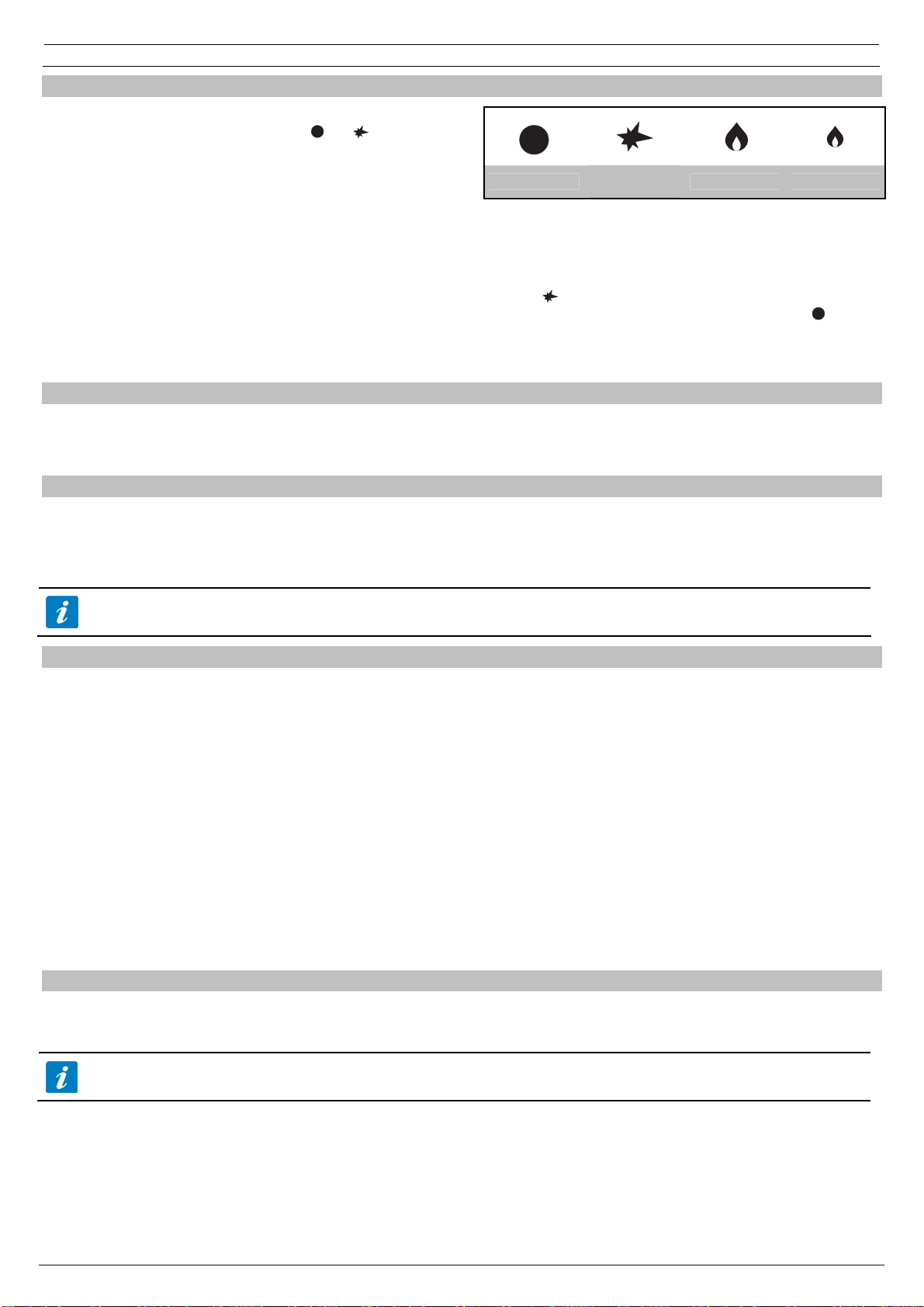
Premere e ruotare la manopola "A" (fig.3) dalla posizione “ ” a " "
mantenendola premuta.
Con un accenditore "W"(fig.2) o un fiammifero innescare la fiamma
pilota. Ad accensione avvenuta mantenere la manopola premuta per
circa 10 secondi (contare fino a venti), si da modo così alla
termocoppia di riscaldarsi e quindi tenere aperta la valvola di
sicurezza.
PIASTRA RISCALDANTE
Nei modelli con piastra sollevare il coperchio "C" (fig.2) e seguire le
istruzioni precedenti.
Per il modello PPC70G7 l'accensione del pilota avviene azionando
ripetutamente il tasto "B" (fig.3) d'accensione.
Per ottenere l'accensione del bruciatore principale ruotare
ulteriormente la manopola fino alla posizione desiderata.
Spento Acc. fiamma
pilota Bruciatore
MAX Bruciatore min
Nota: qualora il dispositivo piezoelettrico fosse inutilizzabile,
l'accensione può avvenire anche manualmente con un fiammifero
oppure con un accenditore gas.
SPEGNIMENTO Bruciatore: Ruotare la manopola dalla posizione in
cui si trova fino alla posizione " ".
SPEGNIMENTO Apparecchio: Ruotare la manopola fino alla
posizione “ ”.
Comportamento in caso di prolungata inattività
Chiudere il rubinetto d’intercettazione gas installato a monte. Effettuare la pulizia con acqua saponata, risciacquare, asciugare con cura e stendere
un leggero strato d’olio di vaselina.
Comportamento in caso di guasti
I guasti non sempre dipendono dalla qualità dei componenti, che nel
nostro caso sono d’ottima fattura, essi possono essere causati anche
da sbalzi di tensione, da polvere o sporco che penetra nei
componenti funzionali.
In qualsiasi caso in cui si sospetta un funzionamento anormale
STACCARE SEMPRE l'alimentazione elettrica e gas ed avvisare il
servizio d’assistenza autorizzato.
Non improvvisarsi manutentori, la manomissione dell'apparecchio implica il decadimento della garanzia.
Controllo del funzionamento
Prima di consegnare l’apparecchio all’utilizzatore eseguire i seguenti
controlli:
PORTATA TERMICA
Controllare che il tipo di gas erogato e la pressione corrispondano a
quanto riportato sulla targhetta. In caso contrario procedere ad una
trasformazione o ad un adattamento; in questo caso consultare il
paragrafo “Trasformazione ed adattamento”.
Controllare che siano installati gli ugelli corretti. Allo scopo consultare
la tabella ugelli e controllare la corrispondenza con quelli montati
sull’apparecchiatura.
Per un controllo supplementare della portata, si può verificare il
consumo di gas con il metodo volumetrico: mettere in funzione il
bruciatore, dopo ca. 10 minuti (condizione a regime) controllare se il
flusso di gas (in m3/h oppure in kg/h) rilevato corrisponde a quanto
riportato nella tabella ugelli.
ASPETTO DI FIAMMA
La fiamma deve essere di colore blu, non deve evidenziare punte
gialle e deve essere stabile alla base. L’aspetto della fiamma con
colore tendente al giallo evidenzia un’errata regolazione dell’aria
primaria. Se l’aria primaria è in eccesso, la fiamma è corta e tende a
staccarsi dal bruciatore. Il controllo dell’aspetto della fiamma deve
essere effettuato anche dopo ca. 15 minuti di funzionamento alla
potenza massima. La fiamma deve restare stabile anche dopo un
passaggio veloce da minimo a massimo.
ISTRUZIONI PER L'UTENTE
L’utente deve essere debitamente istruito sull’impiego corretto, sulle
funzioni e sull’uso dell’apparecchio. Si fa presente che modifiche
all’ambiente d’installazione possono influenzare l’apporto d’aria
comburente e comportano un nuovo controllo del funzionamento
dell’apparecchio. Al termine dei controlli sottoporre l’apparecchio ad
una prova di tenuta.
Sostituzione di parti
La sostituzione di parti difettose, deve essere eseguita
esclusivamente da personale abilitato. Prima di iniziare qualsivoglia
lavoro scollegare l’apparecchio dalla rete di distribuzione del gas.
Dopo aver tolto il pannello portacomandi tutte le parti funzionali
dell'apparecchio diventano facilmente accessibili.
I pezzi di ricambio sono da richiedere esclusivamente al costruttore o ad un rivenditore autorizzato.
IT - 5 5410.263.00
Parte 4 Manutenzione e pulizia
Pulizia e cura
ATTENZIONE: La pulizia deve essere effettuata solamente ad
apparecchio raffreddato.
Si ricorda che la pulizia è molto importante per il buon funzionamento
e per una lunga durata dell’apparecchio.
Le parti asportabili per esempio il cassetto "V" (fig.2) sono da lavare
separatamente con acqua calda e detergente e da sciacquare poi
con acqua corrente.
Le parti d’acciaio si possono pulire con un panno umido e del
detergente assolutamente non abrasivo, si possono infine ripassare
con un panno morbido e asciutto. Per macchie molto resistenti usare
acqua calda e aceto.
La pulizia delle parti d’acciaio inossidabile non sono da impiegare
sostanze aggressive o comunque detergenti abrasivi. L’uso di
paglietta di ferro è sconsigliato poichè può provocare formazione di
ruggine. Per lo stesso motivo evitare il contatto con materiali ferrosi,
stracci pesanti o ruvidi, o con lana d'acciaio.
Durante la pulizia evitare anche l’utilizzo di carta o tela vetrata; in
sostituzione e solo per casi particolari si può usare pietra pomice in
polvere; nel caso di sporco tenace si consiglia l’ausilio di spugne (p.
es. Scotch). In caso di sporco tenace può essere usato anche dello
spray per forni e grill comunemente reperibili. In questo caso
osservare attentamente le avvertenze del produttore.
Manutenzione
L'apparecchiatura non necessita di particolare manutenzione oltre alla normale pulizia; si consiglia comunque un controllo annuale dal
centro d’assistenza e a tale scopo si raccomanda la stipula di un contratto di manutenzione.
Avvertenze per la sicurezza
SI RICORDA CHE L’APPARECCHIO:
■Dev’essere utilizzato solamente sotto sorveglianza!
■Durante l’uso, le superfici diventano molto calde e pertanto si
raccomanda particolare prudenza!
■E’ destinato ad uso professionale e pertanto solo personale
qualificato può utilizzarlo!
■L’installazione nonché un’eventuale trasformazione o un
adattamento ad un altro tipo di gas, possono essere eseguite
secondo le prescrizioni di legge vigenti esclusivamente da
personale qualificato ed autorizzato.
■Almeno una volta l’anno va sottoposto ad un controllo, a cura di
personale qualificato.
■E tutte le parti dell’apparecchiatura, che durante l'uso vanno in
contatto con il cibo, sono da pulire regolarmente seguendo il
capitolo "Pulizia e cura".
INCENDIO:
Nel caso d’incendio chiudere immediatamente il rubinetto
d’intercettazione del gas, ed utilizzare un estintore adeguato.
Il costruttore declina ogni responsabilità nel caso di danni provocati da errata installazione, impropria manutenzione ed inosservanza
delle prescrizioni di sicurezza!
Ecologia e ambiente
Le nostre apparecchiature sono studiate ed ottimizzate, con test di
laboratorio, al fine di ottenere prestazioni e rendimenti elevati.
Comunque, al fine di contenere i consumi energetici (elettricità, gas
ed acqua), si consiglia di evitare l’utilizzo dell’apparecchiatura per
lungo tempo a vuoto o in condizioni che compromettano il
rendimento ottimale.
Tutti i materiali utilizzati per l’imballo sono compatibili con l’ambiente.
Essi possono essere conservati senza pericolo o essere bruciati in
un apposito impianto di combustione dei rifiuti. I componenti in
materiale plastico soggetti a eventuale smaltimento con riciclaggio
sono:
■Polietilene: pellicola esterna dell’imballo e/o pellicola pluribol
■Polipropilene: reggette
■Polistirolo espanso: angolari, lastre e cubi di protezione.
Alla fine del ciclo di vita del prodotto, evitare che l’apparecchiatura
venga dispersa nell’ambiente.
Le nostre apparecchiature sono realizzate con materiali metallici
(acciaio inox, ferro, lamiera alluminata, ecc.) in percentuale superiore
al 90% ed è quindi possibile un riciclaggio degli stessi, per mezzo
delle strutture tradizionali di recupero, nel rispetto delle normative
vigenti nel proprio paese.
Rendere inutilizzabile l’apparecchiatura per lo smaltimento
rimuovendo il cavo d’alimentazione e qualsiasi eventuale dispositivo
di chiusura vani o cavità per evitare che qualcuno possa rimanere
chiuso al loro interno.

GB / IE - 1 5410.263.00
Part 1 Installation
GAS COOKTOPS
General Instructions
The appliance described in this manual has been built to meet UNI
EN 203 and UNI EN 437 standards.
This appliance has been designed exclusively for cooking food, any
other use is considered improper. It should only be used by qualified
personnel in professional kitchens.
The unit must never be left unattended when it is being used! The
appliance should be checked once a year by a qualified technician.
Switch the appliance off in the case of a failure or malfunction.
The appliance should be installed under an extractor hood for removing any cooking fumes.
Care must be taken when using the appliance because the cooking surfaces are very hot.
The appliance must be installed, connected and serviced properly by qualified personnel according to the regulations and
directives in force in the country where it is installed, as well as the instructions in this manual.
Unit characteristics
This instruction manual refers to the installation and use of the
Category II2H3+ gas cooktops.
The self-adhesive polyester data plate "T" (fig.2) is behind the
control panel (inside the appliance).
It contains the following information:
Model PC35G7 PC70G7 PC105G7
Serial number: xxxxxx
Category: II2H3+
Year of construction: XXXX
Nominal thermal capacity: 10.5 kW 19.5 kW 30 kW
Type of construction: A
Test base: UNI EN 203-1
Connection pressure: G30
G20 28-30/37 mbar
20 mbar
Consumption: G30
G20 0.83
1.11
Kg/h
m3/h 1.54
2.06 Kg/h
m3/h 2.36
3.17
Kg/h
m3/h
The supplementary plate is also made of self-adhesive polyester and
is affixed near the data plate; it contains all information regarding the
appliance.
Both the appliances have a fitting for gas connection. The "G" gas
distribution network connection (fig.1) meets ISO 7/1 and ISO 228/1
(DK) standards with a ø ½” connection, situated at the back of the
machine.
Model N. of burners Type
PC35G7 2 Burner
PC70G7 4 Cooker
PC105G7 6 Cooker
PCP70G7 2+1 Cooker + hot plate
PCP105G7 4+1 Cooker + hot plate
PPC70G7 1 Hot plate
The structure of the appliance is made of stainless steel, the burners
are made of cast iron and the oven is made of stainless steel. All
models have adjustable feet.
The main gas pipe is made of galvanised steel. The pipes between
the tap and burner are made of copper.
WARNING! Install a shut-off cock in the line between the
appliance and the gas distribution network.
Connection to the distribution network
Before you install the appliance, make sure that the
gas company has authorised the installation,
compare the data relevant of the appliance (data
plate) with the local supply.
Remove the packaging from the appliance as well as the protective
plastic sheet, and, if necessary, remove traces of glue with a suitable
solvent. To dispose of the packaging, follow local directives (for more
details refer to the chapter “ECOLOGY AND THE ENVIRONMENT”.
Prior to connecting the unit to the gas network, check the data plate
to see if the unit has been set and tested for the type of gas supplied.
If the gas type indicated on the data plate is not the same as that
supplied, please refer to the paragraph “CONVERSION AND
ADAPTATION”.
Connect the appliance to the gas distribution network using metal
pipes with a suitable diameter; install a homologated on/off cock
between the appliance and the distribution network. If flexible pipes
are used they must be made of stainless steel according to the
standards in force. When installing the appliance, all the regulations
in force must be observed, such as:
■UNI-CIG 8723 safety standard, Act n.46 of the 5th of March 1990
and circular n.68.
■Regional and/or local regulations, such as building codes;
■Accident prevention regulations in force;
■Fire prevention regulations;
■Applicable I.E.C. regulations.
We recommend installing the appliance in a well-ventilated
environment, or under an extraction hood to remove the fumes or
vapours produced during the cooking cycle.
The appliance can be installed alone or in line.
Respect a minimum distance of 80mm between the appliance and
any walls made of flammable material, partitions, kitchen furniture or
nearby equipment.
The contact surfaces must be covered with non-combustible heat
insulating material.
The appliance must not be installed near heat sources, the ambient
temperature in the place where the appliance is installed must not
rise to over 50°C.
After installing the appliance check for any leaks in the fittings. Use
non-corrosive foam products, such as leak detection sprays, to look
for any leaks.
GB / IE - 2 5410.263.00
When checking for leaks do not use naked flames!
The manufacturer shall not be held responsible and the guarantee is void in the case of damage caused by negligence in
following the operating and installation instructions or by improper use. The guarantee is void in the case of connections which
have been made in a way which doesn't meet the current standards and fire-fighting regulations.
Evacuation of unburnt gases
This equipment doesn't need to be connected to a flue (A1type of construction), but we do recommend installing it under an extractor hood.
Checking the pressure
The distribution network pressure must meet the following
specifications:
ALLOWED From 20/25 to 35/45 mbar
LPG NOT ALLOWED Below 20/25 above 35/40 mbar
ALLOWED From 17 to 25 mbar
METHANE
H NOT ALLOWED Below 17 above 25 mbar
If the gas distribution network pressure on the installation site doesn't
meet the above values, inform the gas board and do not turn the unit
on until the cause and a solution have been found.
The distribution network pressure can be taken with a U manometer
(min. definition 0.1 mbar), connected to the pressure outlet behind
control panel “H”(fig.5).
1. Remove the control panel.
2. Remove screw "Y" and the sealing washer (fig.5) from the
pressure outlet and connect the manometer.
3. Turn the appliance on following the enclosed instructions and
check that the pressure is within the permitted pressure range.
4. Disconnect the manometer and replace screw "Y" and the
sealing washer (fig.5) in the pressure outlet.
5. Remove the control panel.

GB / IE - 3 5410.263.00
Part 2 Transformation and adaptation
To convert the appliance to another type of gas, e.g. fromnatural gas
to LPG, the nozzles of the main burner, by-pass and pilot light have
to be changed. All the nozzles are marked with a number that
indicates the diameter in 1/100 and are supplied in a bag.
After each conversion or adaptation, the unit must undergo an
operating test and the supplementary plate must be updated
according to the conversion or adaptation carried out.
Connections to the distribution network, installation, and maintenance of the appliance must only be carried out by qualified
technicians only, in observance of all applicable regulations!
Cooktop burner – Nozzles and air adjustment
BURNER:
1. Pull the knobs off.
2. Remove the control panel by unscrewing the fixing screws at the
rear, locate the burners.
3. Replace nozzle "U" (fig.4) with a suitable one for the new type of
gas indicated in the "MAX" nozzles table T1 section
Specifications.
4. Repeat the operation for all the burners.
ADJUSTING THE AIR:
5. Tighten the fixing screw "X" (fig.4).
6. Adjust the primary air by moving the bush a distance “H” (fig.6).
indicated in the nozzles table T1section Specifications.
7. Block the bush, by screwing in fixing screw “X”(fig.4)
PILOT LIGHT:
8. Unscrew and remove closing nut "Z" (fig.4)
9. Unscrew and replace the pilot nozzle (fig.4) with the type
indicated in nozzles table T1 section Specifications.
10. Replace and tighten closing nut "Z" (fig.4)
MINIMUM:
11. Unscrew and replace or adjust nozzle "Um" (fig.5) on the basis
of the indications in nozzles table T1 section Specifications.
12. Replace the control panel, tighten the fixing screws at the rear
and replace the knobs.
GB / IE - 4 5410.263.00
Part 3 Use
Turning the burner of the appliance on and off
COOKTOP BURNERS
Press and turn knob “A” (fig.3) from position “ ” to " " keeping it
pressed in.
Light the pilot light with igniter "W"(fig.2) or a match. After the flame
has lit, hold the knob down for roughly 10 seconds (count to twenty);
so the thermocouple heats up and keeps the safety valve open.
HOT PLATE
In the models with a hot plate, lift cover "C" (fig.2) and follow the
previous instructions.
For model PPC70G7 light the pilot by pressing igniter button "B"
repeatedly (fig.3).
To light the main burner, turn the knob again until it reaches the
desired position.
Off Flame on
pilot light Burner MAX Burner min
Note: if the piezoelectric device cannot be used, you can light the
flame by hand using a match or a gas lighter.
TURNING THE BURNER OFF: Turn the knob from the position it is
in to the “ ” position.
TURNING THE APPLIANCE OFF: Turn the knob to the “ “
position.
What to do if the unit is not going to be used for a long time
Turn the gas shut-off cock installed upstream off. Clean the
appliance with soapy water, rinse, dry carefully and apply a light
layer of liquid paraffin.
Malfunctions
Malfunctions do not always depend on the quality of the components
used. These appliances are manufactured using top quality
components. Failures may be caused by voltage surges, or dust and
dirt in the operating components.
In any situation where improper functioning of the appliance is
suspected, turn it off and DISCONNECT IT FROM THE MAINS. Call
the authorised repair service.
Unauthorised persons should never attempt to repair the appliance, or carry out maintenance. Tampering with the appliance
voids the warranty!
Operational checks
Before the unit is delivered to the user the following checks must be
carried out.
THERMAL CAPACITY
Check that the pressure and type of gas supplied where the unit is to
be used is the same as that indicated on the plate. If it is not, the unit
must either be converted or adapted. In this case please refer to the
paragraph: “Conversion or Adaptation”.
Check that the right nozzles have been installed. Refer to the nozzle
table and check that the nozzles indicated in the table are the same
as those installed on the unit.
An additional check of thermal capacity entails verifying the gas
consumed with the volumetric method: start the burner and after
approximately 10 minutes (in working conditions) check that the gas
flow (in m3/h or in kg/h) corresponds to that in the nozzle table.
APPEARANCE OF THE FLAME
The flame should be blue and there should be no yellow dots in it; it
must be stable at its base.
If the colour of the flame tends towards yellow it means the primary
airflow is not adjusted properly. If the primary airflow is too fast the
flame will be short and tend to burn above the burner.
The appearance of the flame must also be checked 15 minutes after
the appliance has been running at full power. The flame must remain
stable even when passing quickly from minimum to maximum.
USER'S INSTRUCTIONS
The user must be trained on the correct use and functions of the
appliance. We would like to point out that any alterations made to the
room where the unit is installed could influence the amount of air
used for combustion and for this reason the appliance must be
checked again. When these checks have been done, test the unit for
leaks.
Replacing parts
Only qualified personnel should replace faulty parts. Prior to
commencing any kind of work, disconnect the unit from the gas distribution network. After having removed the control panel, all the
functional parts of the appliance are easily accessible.
Only order spare parts from the manufacturer or an authorised reseller.

GB / IE - 5 5410.263.00
Part 4 Maintenance and cleaning
Cleaning and care of the appliance
WARNING! The unit must be cold to clean it.
Keeping the appliance clean is very important for a long and trouble-
free working life.
The removable parts, for example drawer "V" (fig.2) should be
washed separately with warm water and detergent, then rinsed in
running water.
The steel parts may be cleaned with a damp cloth and with a non-
abrasive detergent and then dried by using a soft, dry cloth. For very
resistant stains, use hot water and vinegar.
Do not use harsh or abrasive detergents to clean the stainless steel
parts. Iron cleaning pads should not be used as they cause the
formation of rust. For the same reason, avoid contact with ferrous
materials.
When cleaning, avoid using abrasive paper or cloth; instead and only
in special cases you can use pumice stone powder; we recommend
using sponges (ex. Scotch) to remove stubborn deposits. You can
also use common sprays for cleaning ovens and grills to remove
stubborn deposits. If spray products are used, follow the
manufacturer’s instructions.
Maintenance
The appliance needs no specific maintenance besides normal cleaning; we do however suggest having it checked once a year by the
assistance centre for which, we recommend drawing up a maintenance contract.
Safety precautions
REMEMBER THAT THE APPLIANCE:
■Must never be left unattended when it is being used!
■When the unit is switched on, its surfaces get very hot so please
take great care!
■The appliance is intended for professional use and therefore
only qualified personnel should use it!
■Installation as well as any conversion or adaptation to a different
type of gas must be carried out in accordance with current laws
and only by qualified and authorized personnel.
■At least once a year have the appliance checked by qualified
personnel.
■All the parts that come into contact with oil or fat during use,
should be cleaned regularly as indicated in the chapter
“Cleaning and Care”.
FIRE:
In the case of fire, close the shut-off cock to cut off the gas supply
immediately, then use a suitable fire extinguisher to fight the fire.
The Manufacturer declines any responsibility for damage caused by improper or incorrect installation or maintenance of the appliance, or
failure to observe safety regulations!
Ecology and environment
Our appliances are studied and optimised, with lab tests, to provide
high performance and yields. However, to keep energy consumption
low (electricity, gas and water), we suggest not using the appliance
for any length of time if it is empty or in conditions that compromise
optimum yield.
All packaging materials are environment-friendly. They can be kept
without problem or burnt in a waste incinerator plant. The plastic
components that can be recycled are:
■Polyethylene: external packaging material and/or pluribol film
■Polypropylene: straps
■Polystyrene foam: corner pieces, sheets and protection blocks
At the end of the appliance’s useful life, dispose of it properly.
90% of each appliance is made of metal (stainless steel, iron,
aluminated sheet, etc.) hence it can be recycled by the relative
recycling organisations in compliance with the standards in force in
your country.
Prepare the appliance for disposal, so it cannot be used any more,
by removing the power cable and any locks so that no one can get
locked inside accidentally.

DE / AT / CH - 1 5410.263.00
Teil 1 Installation
GASHERDE
Allgemeine Anmerkungen
Das in diesem Handbuch beschriebene Gerät wurde unter
Beachtung der Anforderungen der Normen UNI_EN 203 und
UNI_EN 437 gebaut.
Dieses Gerät ist ausschließlich für das Kochen und Garen von
Speisen vorgesehen. Jeder andere Gebrauch gilt als ungeeignet. Es
ist für den Einsatz in Großküchen bestimmt und darf nur von
qualifiziertem Personal betrieben werden.
Das Gerät nur unter Aufsicht betreiben! Außerdem ist es
empfehlenswert, einmal jährlich eine Kontrolle von qualifiziertem
Personal durchführen zu lassen.
Im Schadensfall oder bei mangelhaftem Betrieb das Gerät
ausschalten.
Es ist empfehlenswert, das Gerät unter einer Abzugshaube aufzustellen, um die während des Garens erzeugten Dämpfe
abzuleiten.
Es ist besonders darauf zu achten, dass sich die Geräteoberflächen während des Betriebs stark erhitzen.
Der Anschluss, die Installation und die Wartung müssen von Fachpersonal gemäß den Vorschriften und Gesetzen des Landes
sowie in Übereinstimmung mit dieser Gebrauchsanweisung durchgeführt werden.
Angaben zum Gerät
Die vorliegende Installations- und Wartungsanleitung gilt für
Gasherde der Kategorie II2H3+.
Das Typenschild “T” (Abb.2) aus selbsthaftendem Polyester
befindet sich hinter der Bedienungsblende (im Geräteinneren).
Es enthält folgende Daten; Beispiel:
Modell: PC35G7 PC70G7 PC105G7
Seriennummer: xxxxxx
Kategorie: II2H3+
Baujahr: xxxx
Nennwärmebelastung: 10.5 kW 19.5 kW 30 kW
Bauart: A
Prüfgrundlage: UNI EN 203-1
Anschlussdruck: G30
G20 28-30/37 mbar
20 mbar
Anschlusswert.: G30
G20 0.83
1.11
Kg/h
m3/h 1.54
2.06 Kg/h
m3/h 2.36
3.17
Kg/h
m3/h
Das Zusatzschild, ebenfalls aus selbstklebender Polyesterfolie, ist
neben dem Typenschild angebracht und es enthält alle
Informationen über die Einstellung des Gerätes.
Alle Geräte sind mit einer Gasanschlussrampe ausgestattet. Der
Anschluss für die Verbindung mit der Gasleitung "G"(Abb.1)
entspricht den Vorschriften ISO 7/1 und ISO 228/1 (DK) mit ø ½” und
befindet sich an der Geräteunterseite.
Modell: Brennerzahl Typ
PC35G7 2 Flamme
PC70G7 4 Flamme
PC105G7 6 Flamme
PCP70G7 2+1 Flamme + Platte
PCP105G7 4+1 Flamme + Platte
PPC70G7 1 Platte
Die Gerätestruktur ist aus Edelstahl, die Brenner aus Gusseisen und
die des Backofens aus Edelstahl gebaut. Alle Modelle sind mit
höhenverstellbaren Stellfüßen ausgestattet.
Die Gas-Hauptleitung besteht aus verzinktem Stahl, die
Anschlussleitungen vom Hahn zum Brenner aus Kupfer.
ACHTUNG! Zwischen dem Gerät und der Gasversorgungsleitung
einen Absperrhahn einbauen.
Anschluss an die Gasleitung
Vor der Geräteinstallation unbedingt beim
Gasversorgungsunternehmen eine
Installationsgenehmigung einholen und die Daten der
Geräteeinstellung (Typenschild) mit der örtlichen
Gasversorgung konfrontieren.
Die Geräteverpackung entfernen, die Schutzfolie abnehmen und
eventuelle Klebstoffrückstände mit einem geeigneten Lösungsmittel
entfernen. Das Verpackungsmaterial muss vorschriftsmäßig entsorgt
werden (nähere Details dazu im Kapitel „UMWELTSCHUTZ“).
Bevor das Gerät angeschlossen wird, ist auf dem Geräteschild
festzustellen, ob das Gerät für die vorhandene Gasart eingerichtet
und zugelassen ist. Falls die auf dem Geräteschild angegebene
Gasart mit der vorhandenen Gasart nicht übereinstimmt, verweisen
wir auf Abschnitt ”UMSTELLUNG UND ANPASSUNG”.
Der Anschluss an das Gaszuleitungsnetz muss mit Metallrohren mit
entsprechendem Durchmesser und unter Zwischenschaltung eines
anerkannten Absperrhahns durchgeführt werden. Sollten
Schlauchleitungen zur Anwendung kommen, müssen diese gemäß
müssen diese gemäß DIN 3383 Teil 1 oder DIN 3384 (für
Deutschland) und den gültigen Normen aus rostfreiem Stahl (für die
Schweiz und für Österreich) bestehen. Während der Installation sind
alle geltenden Vorschriften zu berücksichtigen:
■Sicherheitsnorm UNI-CIG 8723, Gesetz Nr. 46 vom 5. März 1990
und Rundschreiben Nr. 68.
■Regionale bzw. lokale Bauvorschriften
■Geltende Unfallverhütungsgesetze
■Brandschutzvorschriften
■Entsprechende IEC-Vorschriften
Für Deutschland
■DVGW-Arbeitsblatt G600 (TRGI) „Technische Regeln für
Gasinstallation“.
■TRF „Technische Regeln für Flüssiggas“.
■Richtlinien und Bestimmungen des
Gasversorgungsunternehmens (EUV).
■DVGW-Arbeitsblatt G634 „Installation von Großküchen-
Gasverbrauchseinrichtungen“.
■Einschlägige Rechtsverordnungen.
DE / AT / CH - 2 5410.263.00
Für Schweiz
■SVGW - Gasleitsätze G1 (2002)
■EKAS - Richtlinie Nr. 1942: Flüssiggas, Teil 2 (EKAS:
Eidgenössische Koordinationskommission für
Arbeitssicherheit)
■Vorschriften der Vereinigung Kantonaler Feuerversicherungen
(VKF)
■Richtlinien der SUVA.
Das Gerät kann sowohl freistehend als auch gemeinsam mit anderen
Geräten installiert werden.
Zwischen dem Gerät und eventuellen Wänden ausbrennbarem Material,
Trennwänden, Küchenmöbeln oder nebenstehenden Geräten
mindestens80mmAbstand halten.
Die Kontaktflächen müssen mit nicht brennbarem
Wärmeisoliermaterial verkleidet werden.
Das Gerät nicht in der Nähe von Wärmequellen aufstellen - die
Raumtemperaturum dasGerät darf nicht über 50°Cliegen.
Nach der Installation die Anschlüsse auf ihre Dichtheit prüfen. Zur
Suche nach Leckstellen einen nicht korrosiven Schaum, wie z.B.
Lecksuchsprays verwenden.
Bei der Dichtheitsprüfung auf keinen Fall offene Flammen benutzen!
Der Hersteller übernimmt keine Garantieverpflichtung für Beschädigungen, die aufgrund einer Nichtbeachtung der Installations-
und Bedienungsanleitung oder durch fahrlässige Bedienung entstehen. Außerdem übernimmt er keine Garantieverpflichtungen
für einen nicht mit den gültigen Normen und Brandschutzvorschriften konformen Anschluss.
Abgasabführung
Diese Geräte werden der Bauart A1 zugeordnet, ein Anschluss an einen Kamin ist nicht erforderlich, wobei die Aufstellung unter einer
Dunstabzugshaube jedoch empfehlenswert ist.
Druckkontrolle
Der Leitungsdruck muss folgenden Daten entsprechen:
ZULÄSSIG zwischen 20/25 und 35/45mbar
FLÜSSIGGAS NICHT ZULÄSSIG unter 20/25 bzw. über 35/40mbar
ZULÄSSIG zwischen 17 und 25mbar
ERDGAS
H NICHT ZULÄSSIG unter 17 bzw. über 25mbar
Sollte der Leitungsdruck am Aufstellungsort nicht den oben
genannten Werte entsprechen, das GVU benachrichtigen und keine
Inbetriebnahme vornehmen, bevor die Ursache nicht geklärt und
behoben ist.
Der Druck ist mit einem U-Rohr Manometer (Auflösung mind. 0.1
mbar) messbar. Das Manometer kann am Druckanschluss “H”
(Abb.5) hinter der Blende angeschlossen werden.
1. Die Bedienblende abnehmen.
2. Die Schraube und Dichtungsscheibe “Y” (Abb. 5) vom
Druckanschluss nehmen und das Manometer anschließen.
3. Gerät gemäß der Bedienungsanleitung in Betrieb nehmen und
prüfen, ob der angegebene Druck im zulässigen Bereich liegt.
4. Das Manometer wieder abnehmen und die Schraube „Y“ mit
dem Dichtring (Abb.5) wieder am Druckanschluss anordnen.
5. Die Bedienblende wieder montieren.
DE / AT / CH - 3 5410.263.00
Teil 2 Umstellung und Anpassung
Die Umstellung auf eine andere Gasart z.B. von Erdgas auf
Flüssiggas erfolgt durch den Austausch der Hauptbrenner-, Bypass-
und Zündbrennerdüsen. Alle Düsen sind mit einer Ziffer
(Durchmesser in 1/100) gekennzeichnet und in einem Beutel
mitgeliefert.
Nach jeder Umstellung oder Anpassung ist eine Funktionskontrolle
vorzunehmen und das Zusatzschild entsprechend der erfolgten
Umstellung bzw. Anpassung zu ändern.
Alle Maßnahmen bezüglich Anschluss, Installation sowie Wartung des Gerätes dürfen nur von qualifiziertem Personal unter
Beachtung aller entsprechenden Vorschriften durchgeführt werden!
Kochplattenbrenner – Düsen und Lufteinstellung
BRENNER:
1. Die Drehschalter herausziehen.
2. Die Bedienblende mittels Ausschrauben der
Befestigungsschrauben abnehmen und die Brenner ausfindig
machen.
3. Die Düse „U“ (Abb.4) durch die für die neue Gasart geeignete
ersetzen - siehe „MAX“ in der Düsentabelle - T1 im Abschnitt
Technische Daten.
4. Die Maßnahme für alle Brenner wiederholen.
LUFTEINSTELLUNG:
5. Die Befestigungsschraube „X“ (Abb.4) ausschrauben.
6. Die Primärluft durch Einstellung der Büchse bis auf den Abstand
“H” (Abb.6) der Düsentabelle T1 im Abschnitt Technisch
Daten verstellen.
7. Die Büchse durch Einschrauben der Schraube “X” (Abb.4)
befestigen.
ZÜNDBRENNER:
8. Die Verschlussmutter “Z” (Abb.4) ausschrauben und abnehmen.
9. Die Düse des Zündbrenners “D” (Abb.4) aufgrund der Angaben
in der Düsentabelle - T1 im Abschnitt Technische Daten
ausschrauben und austauschen.
10. Die Verschlussmutter „Z“ (Abb.4) wieder einschrauben
KLEINSTSTELLUNG:
11. Die Kleinststelldüse "Um" (Abb.5) laut Düsentabelle - T1 im
Abschnitt Technische Daten ausschrauben und austauschen.
12. Die Bedienblende wieder montieren, die Schrauben unten
wieder einschrauben und alle Drehschalter wieder einsetzen.

DE / AT / CH - 4 5410.263.00
Teil 3 Gebrauch
Inbetriebnahme des Geräts und Zünden des Brenners
KOCHPLATTENBRENNER
Den Drehschalter “A” (Abb.3) drücken und von “ ” auf " " drehen.
Mit einem Gaszünder "W"(Abb.2) oder einem Streichholz die
Zündflamme anzünden. Nach der Zündung den Drehschalter ca.
weitere 10 Sekunden (bis 20 zählen) drücken; dadurch erhitzt sich
das Thermoelement und hält das Sicherheitsventil offen.
WARMHALTEPLATTE
Bei den Modellen mit Platte den Deckel "C" (Abb.2) anheben und die
oben angeführten Schritte befolgen.
Beim Modell PPC70G7 erfolgt das Zünden des Zündbrenners durch
wiederholtes Drücken des Zündschalters "B" (Abb.3).
Zum Zünden des Hauptbrenners den Drehschalter auf die
gewünschte Stellung drehen.
aus Zündbrenner
zünden Brenner MAX Brenner
MIN
Hinweis: Sollte der Piezozünder gebrauchsunfähig sein, kann die
Zündung auch händisch, unter der Anwendung eines Streichholzes
oder eines Gaszünders erfolgen.
AUSSCHALTEN DES BRENNERS: Den Drehschalter auf Position
“” drehen.
AUSSERBETRIEBNAHME DES GERÄTS: Den Drehschalter auf
Position “ “ drehen.
Verhalten bei längerem Betriebsstillstand
Den bauseitigen Gasabsperrhahn schließen. Das Gerät mit
Seifenwasser reinigen, nachspülen, gründlich trocken reiben und
eine dünne Schicht Vaselinöl auftragen.
Verhalten im Schadensfall
Nicht immer hängt ein Schaden von der Qualität der Bestandteile ab,
die in unserem Fall erstklassig ist. Schäden können durch einen
plötzlichen Stromwechsel, Staub oder Schmutz, der in die
Betriebsteile eintritt, verursacht werden.
Sollte der Verdacht auf eine Betriebsstörung des Gerätes vorliegen,
ist IMMER die Strom- und Gasversorgung zu unterbrechen und der
autorisierte Kundendienst zu verständigen.
Auf keinen Fall dürfen unbefugte Personen versuchen, die Reparatur durchzuführen. Dadurch verfällt die Garantie.
Funktionsprüfung
Das Gerät ist vor der Übergabe an den Benutzer auf nachfolgende
Punkte zu kontrollieren.
THERMISCHE LEISTUNG
Überprüfen, ob die am Aufstellungsort vorhandene Gasart und der
Druck mit den Angaben des Typenschilds übereinstimmen. Sollte
das nicht der Fall sein, ist eine Umstellung oder Anpassung
vorzunehmen, dazu verweisen wir auf Abschnitt ”Umstellung und
Anpassung”.
Prüfen, ob die richtigen Düsen installiert sind. Dazu in der
Düsentabelle nachsehen und sicherstellen, dass die am Gerät
installierten Düsen den Angaben entsprechen.
Zur zusätzlichen Kontrolle kann eine volumetrische Messung des
Gasdurchflusses vorgenommen werden. Dazu den Brenner in
Betrieb nehmen, nach ca. 10 Minuten (Erreichen des
Betriebsregimes) mit einem Gaszähler prüfen, ob der gemessene
Durchfluss (in m3/h bzw. kg/h) den Angaben der Düsentabelle
entspricht.
FLAMMENBILD
Die Flamme muss eine blaue Farbe, ohne gelbe Spitzen, aufweisen
und an der Basis stabil brennen.
Wenn das Flammenbild gelb durchzogen ist, ist die Primärluft nicht
richtig eingestellt. Bei zu großem Primärluft-Volumenstrom ist die
Flammekurzundneigt zurAbhebungvom Brenner.
Die Überprüfung des Flammenbilds muss auch nach einer
Betriebsdauer von 15 Minuten bei Höchstleistung erfolgen. Die
Flamme muss auch nach einer jähen Umstellung von der Klein- in
die Großstellung stabil brennen.
ANWEISUNGEN FÜR DEN BENUTZER
Dem Benutzer die Funktionen und den korrekten Gebrauch und Einsatz
des Gerätes erklären. Darauf hinweisen, dass bauliche Änderungen, die
die Verbrennungsluftzufuhr beeinflussen können, einer erneuten
Funktionskontrolle des Gerätes bedürfen. Zum Abschluss das Gerät auf
Gasdichtheitprüfen.
Austausch von Teilen
Der Austausch von defekten Teilen hat nur durch Fachpersonal zu
erfolgen. Bevor jegliche Arbeit angefangen wird, ist grundsätzlich der
Gasabsperrhahn zu schließen.
Nach Abnahme der Bedienblende sind alle Funktionsteile des
Gerätes leicht zugänglich.
Die Ersatzteile ausschließlich beim Hersteller oder befugten Händlerbestellen.
DE / AT / CH - 5 5410.263.00
Teil 4 Wartung und Reinigung
Reinigung und Instandhaltung
ACHTUNG:
Die Reinigung ist nur bei abgekühltem Gerät vorzunehmen.
Die Reinigung ist für einen einwandfreien Betrieb und eine lange
Lebensdauer des Geräts sehr wichtig.
Die abnehmbaren Teile, wie zum Beispiel die Lade "V" (Abb. 2)
separat mit warmem Wasser und Reinigungsmittel waschen und
unter fließendem Wasser nachspülen.
Die Geräteteile aus Stahl können mit einem feuchten Lappen und
einem nicht scheuernden Mittel gereinigt und danach mit einem
trockenen, weichen Lappen trocken gewischt werden. Für besonders
hartnäckige Flecken ist warmes Wasser und Essig anzuwenden.
Zur Reinigung der Teile aus rostfreiem Stahl, keine aggressive Mittel
oder scheuernde Reinigungsmittel verwenden. Die Benutzung von
Stahlwolle auf Edelstahlteilen ist zu vermeiden, da sich hierdurch
Rost bilden könnte. Aus demselben Grund ist der Kontakt mit
eisenhältigem Material, schweren oder rauen Lappen bzw. mit
Stahlwolle zu meiden.
Glaspapier oder Schmirgelpapier sollten bei der Reinigung nicht
verwendet werden; man kann in besonderen Fällen pulverförmigen
Bimsstein verwenden; bei stärkerer Verschmutzung empfehlen wir
die Benutzung von Schwämmen (z.B. Schwamm der Fa. Scotch).
Bei hartnäckigen Verschmutzungen kann handelsüblicher Backofen-
und Grillreiniger zur Hilfe genommen werden. Dazu sind die
Hinweise des jeweiligen Herstellers zu beachten.
Wartung
Das Gerät benötigt neben der normalen, regelmäßigen Reinigung keine besonderen Wartungsarbeiten; es wird dennoch eine jährliche
Kontrolle durch eine Kundendienststelle empfohlen, weshalb der Abschluss eines Wartungsvertrages ratsam ist.
Sicherheitshinweise
FOLGENDES BEACHTEN:
■Das Gerät nur unter Aufsicht betreiben!
■Während des Betriebs werden die Geräteoberflächen heiß -
besonders Acht geben!
■Das Gerät ist für gewerbliche Zwecke geplant und darf nur
durch Fachpersonal bedient werden!
■Die Geräteinstallation sowie eine eventuelle Umstellung oder
Anpassung auf eine andere Gasart, darf nur gemäß den
einschlägigen gesetzlichen Vorschriften und durch qualifiziertes
Fachpersonal, durchgeführt werden.
■Das Gerät mindestens einmal jährlich von Fachpersonal
kontrollieren lassen.
■Alle Geräteteile, die während des Gebrauchs mit den Speisen in
Verbindung treten, sind gemäß Kapitel “Reinigung und
Wartung” regelmäßig zu reinigen.
BRAND:
Im Brandfall sofort den Gasabsperrhahn schließen und einen
geeigneten Feuerlöscher verwenden.
Der Hersteller übernimmt für Schäden aufgrund falscher Installation, unsachgemäßer Wartung und Nichtbeachtung der
Sicherheitsvorschriften keine Haftung.
Umweltschutz
Unsere Geräte werden durch zahlreiche Laboruntersuchungen
geprüft und optimiert, um so besonders hohe Leistungen zu erzielen.
Dennoch wird zur Einschränkung des Energieverbrauchs (Strom,
Gas und Wasser) empfohlen, das Gerät nicht für längere Zeit
unbenutzt eingeschaltet zu lassen und es nur unter optimalen
Betriebsbedingungen zu verwenden.
Alle für die Verpackung verwendeten Materialien sind
umweltverträglich. Sie können daher ohne Gefahr aufbewahrt oder in
einer dafür vorgesehenen Müllverbrennungsanlage verbrannt
werden. Die folgenden Kunststoffteile sind für eine eventuelle
Wiederverwertung geeignet:
■Polyäthylen: Außenhülle der Verpackung und/oder Noppenfolie
■Polypropylen: Bänder
■Polystyrolschaum: winkel- oder würfelförmiges Schutzmaterial
sowie Schutzabdeckungen
Nach Ablauf der vorgesehenen Lebensdauer des Gerätes ist dieses
ordnungsgemäß zu entsorgen.
Alle unsere Geräte werden zu mehr als 90% aus Metall hergestellt
(Edelstahl, Eisen, Aluminiumblech usw.), sie können daher den
jeweiligen ortsüblichen Entsorgungsstellen problemlos zur
Wiederverwertung zugeführt werden.
Vor der Entsorgung sind die Geräte funktionsuntüchtig zu machen,
indem das Netzkabel am Gerät abgeschnitten wird. Eventuell
vorhandene Verschlussvorrichtungen an Geräteinnenräumen oder
an der Oberseite des Gerätes entfernen, damit sich niemand darin
einschließen kann.

РУ - 1 5410.263.00
Часть 1 Установка
ГАЗОВЫЕ ПОВЕРХНОСТИ ГОТОВКИ
Основные Предупреждения
Оборудование, описанное вданной инструкции реализовано в
соответствии среквизитами норм UNI EN 203,UNI EN 437.
Это оборудование создано только для готовки продуктов, любое
другое использование невозможно; оборудование
предназначено только для профессиональной работы со
стороны квалифицированного персонала.
Оборудование должно работать только под присмотром.
Рекомендуется, кроме этого, производить годовой контроль со
стороны квалифицированных профессионалов.
Дизактивировать оборудование вслучае поломки или
аномальной работы.
Рекомендуется устанавливать оборудование под вытяжной трубой для обеспечивания вытяжки паров, произведенных
во время готовки.
Быть внимательным во время готовки потому что поверхности готовки могут быть очень горячими. Подсоединение,
инсталляция иобслуживание оборудования должны быть проведены квалифицированным персоналом согласно
нормам ипредписаниям, действующим вданной стране ивсоответствии снастоящей инструкцией.
Характеристики оборудования
Настоящие инструкции по инсталляции ииспользованию
относяться кгазовым поверхностям приготовления кухням
категории II2H3+.
Идентификационная табличка из самоклеющегося полиестра
“T” (рис.2) находиться взадней части панели управления
(внутри оборудования).
Она содержит следующие данные:
Moдель: PC35G7 PC70G7 PC105G7
Серийный номер: xxxxxx
Категория: II2H3+
Год выпука: xxxx
Номинальный терморасход: 10.5 kW 19.5 kW 30 kW
Tип конструкции: A
Пробная база: UNI EN 203-1
Давления
подсоединения: G30
G20 28-30/37 mbar
20 mbar
Расход: G30
G20 0.83
1.11
Kg/h
m3/h 1.54
2.06 Kg/h
m3/h 2.36
3.17
Kg/h
m3/h
Дополнительная табличка из самонаклеивающегося полиестра
находиться рядом сидентификационной табличкой, она
сожержит всю информацию по предрасположению
оборудования.
Все оборудование имеет рампу для газового подсоединения.
Контакт для подсоединения кгазовой сети “G” (рис.1)
соответствует предписаниям ISO 7/1 иISO 228/1 (DK) с
контактом ø ½”, он расположен взадней части машины.
Moдель N° горелок Tип
PC35G7 2 Горелка
PC70G7 4 Горелка
PC105G7 6 Горелка
PCP70G7 2+1 Горелка + Плитка
PCP105G7 4+1 Горелка + Плитка
PPC70G7 1 Плитка
Структура оборудования сделана из нержавеющей стали;
форсунки сделаны из чугуна ииз нержавеющей стали для печи.
Все модели оборудования имеют регулирующиеся ввысоту
ножки.
Главный проводник газа сделан из оцинкованной стали.
Проводник подсоединения от крана кфорсунке сделан из
бронзы.
ВНИМАНИЕ!
Расположить между оборудованием исетью распределения
газа кран перехвата.
Подсоединение ксети
Прежде чем приступить кинсталляции оборудования
необходимо запросить вучреждении по выпуску газа
разрешение на инсталляцию, затем сравнить его
данные сотносящимися кпредрасположению
оборудования (табличка характеристик).
Снять упаковку оборудования, убрать защитную пленку, если
необходимо удалисть остатки клея спомощью специального
растворителя.
Рекомендуется переработать упаковку всоответствии с
существующими нормами ( для разъяснения деталей смотреть
главу «ЭКОЛОГИЯ ИОКРУЖАЮЩАЯ СРЕДА»).
Прежде чем подсоединять оборудование ксети,
проконтролировать на идентификационной табличке, если
оборудование предрасположено ииспытано для выпускаемого
типа газа. Если тип газа не соответствует указанному на
идентификационной табличке, проконсультировать параграф
«ТРАНСФОРМАЦИЯ ИАДАПТИРОВАНИЕ».
Рекомендуется устанавливать оборудование вхорошо
проветриваемом помещении ипод вытяжной трубой для
эвакуации паров, произведенных во время готовки.
Оборудование может быть установлено отдельно или батареей.
Оставлять минимальную дистанцию в80 см. между
оборудованием ивозможной стенкой из невозгораемого
материала, разделительными панелями, кухонной мебелью или
близлежащим оборудованием..
Поверхности, находящиеся вконтакте соборудованием должны
быть покрыты термоизоляционным материалом несгораемого
типа.
Оборудование иособенно провод питания, не должно быть
установлено около источников жара, температура около
оборудования не должна превышать 50°C.
Просле инсталляции необходимо приступить к
контролюгерметичности соединений. Для установления
возможных утечек рекомендуется использовать пенные не
коррозивные средства, например, спрай определяющий утечки.
This manual suits for next models
11
Table of contents
Languages:
Other Tecnoinox Cooktop manuals


