Tecnoma ECO User manual
Operating instructions
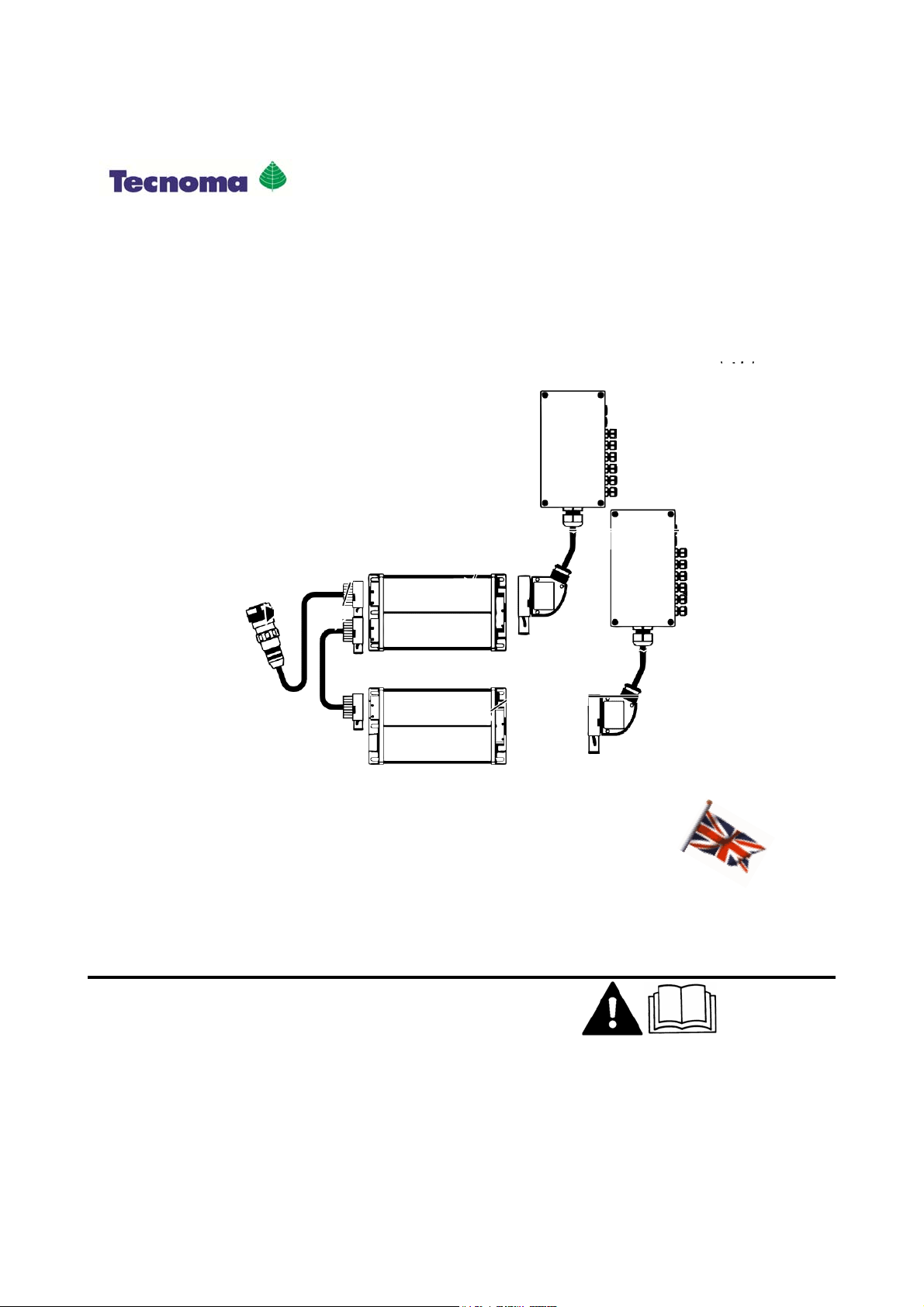
Job computer ECO
990267EN
SEPTEMBER 2014
Read and follow these operating instructions.
Keep these operating instructions in a safe place for later
reference.

Imprint
Operating instructions
Product: Job computer ECO
Document number: 990267EN
From software version: SPRECO1: V619a; SPRECO2: 629a
Original language: German
Document

Contents
3 990267EN ind. A
Contents
1 For your safety 7
1.1 Basic safety instructions 7
1.2 Layout and meaning of warnings 7
1.3 Layout and meaning of alert messages 8
1.4 User requirements 8
1.5 Intended use 9
1.6 EC declaration of conformity 9
1.7 Disposing 9
1.8 Safety sign for the field sprayer 9
1.9 Safety sticker on the product 10
2 About this operating manual 11
2.1 Target group of these Operating Instructions 11
2.2 Illustrations in these operating instructions 11
2.3 Layout of operating instructions 11
2.4 Layout of references 12
3 Product description 13
3.1 Performance description 13
3.2 System requirements 13
3.3 Understanding manufacturer's plates 13
4 Mounting and installation 15
4.1 System overview 15
4.2 Connecting job computer to the basic tractor equipment 16
4.3 Fitting multi-function joystick (MFG) 17
4.4 Mounting the gyroscope 18
4.4.1 Mounting the bracket for the gyroscope 19
4.4.2 Using the gyroscope 20
5 Basic control principles 21
5.1 Switching job computer on and off 21
5.2 Initial start-up 21
5.3 Job computer in the terminal selection menu 22
5.4 Browsing between screens 22
5.5 Inputting data 22
5.6 Screen structure 23
5.6.1 Work screen with a field sprayer 23
5.6.2 Spray data area 24

Contents
4 990267EN ind. A
5.6.3 Selectable area 1 25
5.6.4 Boom terminal area 26
5.6.5 Selectable area 2 28
5.6.6 Function icons 29
5.6.7 Layout of additional screens 29
6 Preparing job computer sprayer for use 30
6.1 When should you configure what? 30
6.2 Entering field sprayer parameters 30
6.3 Options activation 33
6.3.1 Setting sections switching type 34
6.3.2 Setting filling type 34
6.3.3 Setting joystick type 34
6.3.4 Setting manifold type 34
6.3.5 Establishing CAN connection type 35
6.4 Calibrating the flow meter 35
6.4.1 Calibrating the flow meter with the tank method 35
6.4.2 Calibrating the flow meter with the nozzle method 37
6.4.3 Manually entering the number of pulses per liter for the flow meter 39
6.5 Calibrating the wheel sensor 40
6.5.1 Determining pulses per 100 meters 40
6.6 Configuring sections 41
6.6.1 Entering the number of sections 41
6.6.2 Entering the number of nozzles per section 42
6.6.3 Switching off section permanently 42
6.7 Configuring nozzles 43
6.7.1 Layout of the "NOZZLE/PRESSURE" screen 43
6.7.2 Selecting nozzle type 43
6.7.3 Calculating theoretical application rates 45
6.7.4 Calibrating nozzles 46
6.7.5 Configuring wide area nozzles 47
6.8 Tank filling 48
6.8.1 Filling up the tank manually without additional systems 48
6.8.2 Filling up the tank with TANK-Control 49
6.9 Setting sprayer geometry 49
7 Operating job computer sprayer on the field 52
7.1 Controlling boom 52
7.1.1 Locking boom 52
7.1.2 Folding boom in and out 52
7.1.3 Raising and lowering boom 55
7.1.4 Sloping boom 56
7.1.5 Tilting booms up and down 56
7.2 Controlling application 57
7.2.1 Setting rate 57
7.2.2 Changing application mode 57
Using Automatic mode 58
Changing application rate in manual mode 59

Contents
5 990267EN ind. A
7.2.3 Starting spreading 60
7.2.4 Stopping spreading 60
7.2.5 Operating sections 60
Activating corner nozzles 61
Operating wide area nozzles 62
7.2.6 Switching foam marker on and off 63
7.2.7 Dealing with weed infestations 63
Work screen in localized mode 63
Preselecting and switching off sections in localized mode 64
Activating localized mode 64
Multi-function joystick in localized mode 64
7.2.8 Operating PWM regulation 65
7.3 Documenting work results 66
7.4 Operating the multi-function joystick 67
7.5 Operating additional functions 67
8 DISTANCE-Control 68
8.1 Safety mechanisms 68
8.2 Mode of operation 68
8.3 Configuring DISTANCE-Control 69
8.3.1 Calibrating DISTANCE-Control 69
8.3.2 Configuring work height 72
8.3.3 Configuring clearance height 73
8.3.4 Selecting work mode 75
8.4 Operating DISTANCE-Control while working 76
9 TRAIL-Control 77
9.1 Configuring TRAIL-Control 77
9.1.1 TRAIL-Control parameters 77
9.1.2 Calibrating TRAIL-Control 77
Teaching-in the middle position and end stops 78
Calibrating the hydraulics of the proportional valve 80
9.2 TRAIL-Control – Using drawbar and axle steering 81
9.2.1 Steering the trailer device 82
Steering in automatic mode 82
Steering in manual mode 82
Steering the trailer device against the slope 83
9.2.2 Preparing TRAIL-Control for road driving 84
Locking TRAIL-Control 84
10 Cooperation with other applications 86
10.1 TaskManager 86
10.2 SECTION-Control 86
11 Maintenance and technical data 87
11.1 Preparing system for winter rest 87

Contents
6 990267EN ind. A
11.2 Technical data 87
11.2.1 Technical data for the job computer 87
11.2.2 Field sprayer technical data 88
11.3 Checking the software version 89
11.4 Fault diagnostics 89
11.4.1 “Simulated speed“ function 89
11.5 Multi-function joystick button assignment 90
12 Alarm messages 92
For your safety
7 990267EN ind. A
For your safety
Basic safety instructions
Please read the following safety instructions carefully before operating the product for the first time.
▪Before you leave the vehicle cabin, ensure all automatic mechanisms are deactivated or manual
mode is activated. In particular deactivate the systems:
– TRAIL-Control
– DISTANCE-Control
▪Keep children away from the trailer device and from the job computer.
▪Do not make any unauthorized modifications to the product. Unauthorized modifications or use
may impair safety and reduce the service life or operability of the unit. Modifications are
considered unauthorized if they are not described in the product documentation.
▪Never remove any safety mechanisms or stickers from the product.
▪Carefully read and follow all safety instructions in this operating guide and in the field sprayer
operating instructions.
▪Observe all applicable regulations on accident prevention.
▪Follow all recognised safety, industrial and medical rules as well as all road traffic laws.
▪Before charging the tractor battery, always disconnect the tractor from the job computer.
▪Use only clear water when you are testing the field sprayer. Do not use a poisonous spray during
the tests or when calibrating the systems.
Layout and meaning of warnings
All safety instructions found in these Operating Instructions are composed in accordance with the
following pattern:
WARNING
This signal word identifies medium-risk hazards, which could potentially cause death or serious
bodily injury, if not avoided.
CAUTION
This signal word identifies low-risk hazards, which could potentially cause minor or moderate bodily
injury or damage to property, if not avoided.
NOTICE
This signal word identifies actions which could lead to operational malfunctions if performed
incorrectly.
These actions require that you operate in a precise and cautious manner in order to produce
optimum work results.
There are some actions that need to be performed in several steps. If there is a risk involved in
carrying out any of these steps, a safety warning will appear in the instructions themselves.
1
1.1
1.2

For your safety
8 990267EN ind. A
Safety instructions always directly precede the step involving risk and can be identified by their bold
font type and a signal word.
1. NOTICE! This is a notice. It warns that there is a risk involved in the next step.
2. Step involving risk.
Layout and meaning of alert messages
While working with the field sprayer, an alarm message may appear.
The alarm messages have the following purpose:
▪Warn – They warn the operator if the current state of the field sprayer could lead to a dangerous
situation.
▪Inform – They inform the operator that the current state of the field sprayer or the configuration
is not correct and can lead to faults in operation.
On the following diagram, you can see how the alarm messages are structured:
Layout of alarm messages
Type of alarm Name of the component that caused the
alarm.
"ALARMS" message Problem description and solution
What the exact cause of an alarm message is
or how you rectify a fault can be read in the
section "Alarm messages [➙92]"
Type of alarm
There are three types of alarm:
▪Info
The status of a sensor has changed. If applicable, you must do something.
▪Error
An error has occurred.
▪Danger
Faults that are dangerous. With these alarms, break off work immediately, find out the cause and
rectify the problem.
User requirements
▪Learn to operate the product in accordance with the instructions. Nobody must operate the
product before reading these Operating Instructions.
▪Please read and carefully observe all safety instructions and warnings contained in these
Operating Instructions and in the manuals of any connected machines and farm equipment.
Example
1.3
Purpose
Illustration
1.4

For your safety
9 990267EN ind. A
▪If there is anything within these Operating Instructions that you do not understand, please do not
hesitate to contact us or your dealer. Müller-Elektronik's Customer Services department will be
happy to assist you.
Intended use
The job computer is used to control field sprayers in agriculture. The manufacturer shall not be held
responsible for any installation or use that goes beyond this.
Intended use also includes the adherence to the conditions for operation and repairs prescribed by
the manufacturer.
The manufacturer cannot be held liable for any personal injury or property damage resulting from
such non-observance. All risk involved during improper use lies with the user.
All applicable accident prevention regulations and all other generally recognized safety, industrial,
and medical rules as well as all road traffic laws must be observed. Any unauthorized modifications
made to the unit will void the manufacturer's warranty.
EC declaration of conformity
This product has been manufactured in conformity with the following national and harmonised
standards as specified in the current EMC Directive 2004/108/EC:
▪EN ISO 14982
Disposing
When it has reached the end of its service life, please dispose of this product as
electronic scrap in accordance with all applicable waste management laws.
Safety sign for the field sprayer
If the field sprayer is fitted with drawbar steering or with axle steering, everyone approaching the field
sprayer must be warned of possible dangers. For that reason you receive a safety sign.
1. Stick the safety sign in the appropriate place.
The following rules apply to attaching safety signs:
▪Safety signs must be attached at a visible location so that they can be seen by everyone
approaching the danger zone.
▪If the danger area can be approached from several sides of the machine, attach the warning
signs on all machine sides.
▪Regularly check the safety signs for completeness and legibility.
▪Replace damaged or unreadable signs with new ones.
1.5
1.6
1.7
1.8

For your safety
10 990267EN ind. A
Safety sign Where to attach Meaning
Close to the bend area, between tractor
and trailer device
Do not stay in the bend area
during operation.
Safety sticker on the product
Sticker on the job computer
Do not clean with a high-pressure cleaner.
1.9

About this operating manual
11 990267EN ind. A
About this operating manual
Target group of these Operating Instructions
These operating instructions are intended for operators of field sprayers. The field sprayers must be
fitted with the System Sprayer Controller Midi.
Illustrations in these operating instructions
The role of the diagrams on the software interface is to serve as a reference. They help you in finding
your way around the software screens.
The information shown on the screen is dependent on various factors:
▪the type of field sprayer,
▪the configuration of the field sprayer,
▪the condition of the field sprayer,
For this reason the diagrams in these operating instructions may show different information from the
terminal.
The instructions were written for the operation of the job computer on terminals from Müller-
Elektronik. If the job computer is operated with other ISOBUS terminals, the screen layout and the
information represented may differ from the diagrams in this operating manual.
Layout of operating instructions
The operating instructions explain step by step how you can perform certain operations with the
product.
We use the following symbols throughout these Operating Instructions to identify different operating
instructions:
Type of depiction Meaning
1.
2.
Actions that must be performed in succession.
⇨Result of the action.
This will happen when you perform an action.
⇨Result of an operating instruction.
This will happen when you have completed all
steps.
Requirements.
In the event that any requirements have been
specified, these must be met before an action
can be performed.
2
2.1
2.2
2.3

About this operating manual
12 990267EN ind. A
Layout of references
If any references are given in these Operating Instructions, they will appear thus:
Example of a reference: [➙12]
References can be identified by their square brackets and an arrow. The number following the arrow
shows you on what page the chapter starts where you can find further information.
2.4

Product description
13 990267EN ind. A
Product description
Performance description
The system may consist of one or two job computers depending on how many of the field sprayer
functions are to be controlled via the terminal.
Job computer F1 has the following functions:
▪Up to nine sections switchings with main section switch
▪Manual and automatic control of the spread rate
▪Display of current speed
▪Display of current spread rate
▪Display of remaining workable area
▪Display of the current tank content
▪Documentation of work results
▪DISTANCE-Control – automatic control of the boom height.
▪Raising and lowering boom manually
▪Sloping boom manually
Job computer F2 has these functions:
▪Several hydraulics functions. For example: Sloping the boom, folding the boom in and out.
▪TRAIL-Control – automatic drawbar and axle steering.
System requirements
For the job computer to be used, the tractor must meet the following requirements:
▪For ISOBUS systems:
– The tractor must be fitted with basic ISOBUS equipment.
– The terminal must be ISOBUS-compliant.
▪For ECO systems:
– The tractor must be fitted with basic ECO equipment.
– An ECO terminal from Müller-Elektronik must be fitted to the tractor.
Understanding manufacturer's plates
On the job computer you will find a manufacturer's plate in the form of a sticker. On this sticker you
can find all the information you need to clearly identify the product.
Have these details ready when you contact Customer Services.
Manufacturer's plate on the side of the job computer
3
3.1
3.2
3.3

Product description
14 990267EN ind. A
Item name
In the name you can see whether the job
computer is F1 or F2.
Hardware version
Serial number Customer number
If the product was manufactured for an
agricultural machinery manufacturer, the
agricultural machinery manufacturer's item
number will be shown here.
Software version
If you update the software, this version will no
longer be up-to-date.
Operating voltage
The product may only be connected to
voltages within this range.
Mounting and installation
15 990267EN ind. A
Mounting and installation
System overview
The job computers F1 and F2 are not sufficient on their own to be able to control and operate a field
sprayer.
In the following images you can see what components need to be fitted to your field sprayer and the
tractor.
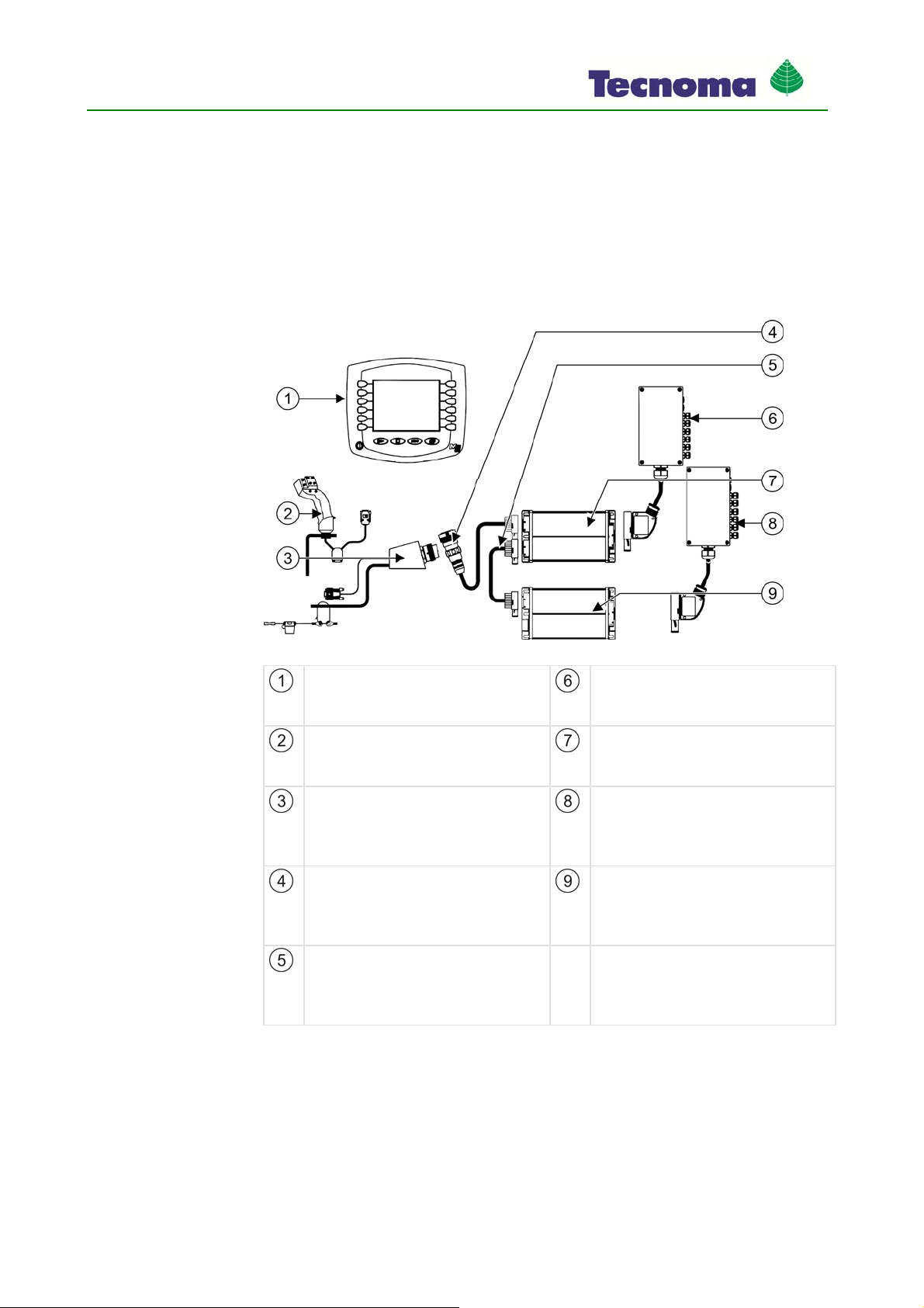
System overview of job computer on a tractor without ISOBUS interface
Terminal
- ISOBUS terminal from Müller-Elektronik with
license "ISO11587 VT"
Cable harness and distributor for job
computer F2
Different configurations are possible.
Multi-function joystick
Optional
- Used to operate the field sprayer.
Job computer F2
Slave job computer
Different configurations possible
ISOBUS basic equipment
- Connects the job computers with the tractor.
- Supplies the job computers and the terminal
with voltage.
Cable harness and distributor for job
computer F1
Different configurations possible
Connection cable for ISOBUS basic
equipment
Connection of the job computers to the
tractor's basic equipment
Job computer F1
Master job computer
Different configurations possible
Connector cable
Connects job computer F1 and job computer
F2
Different configurations possible
4
4.1
Mounting and installation
16 990267EN ind. A
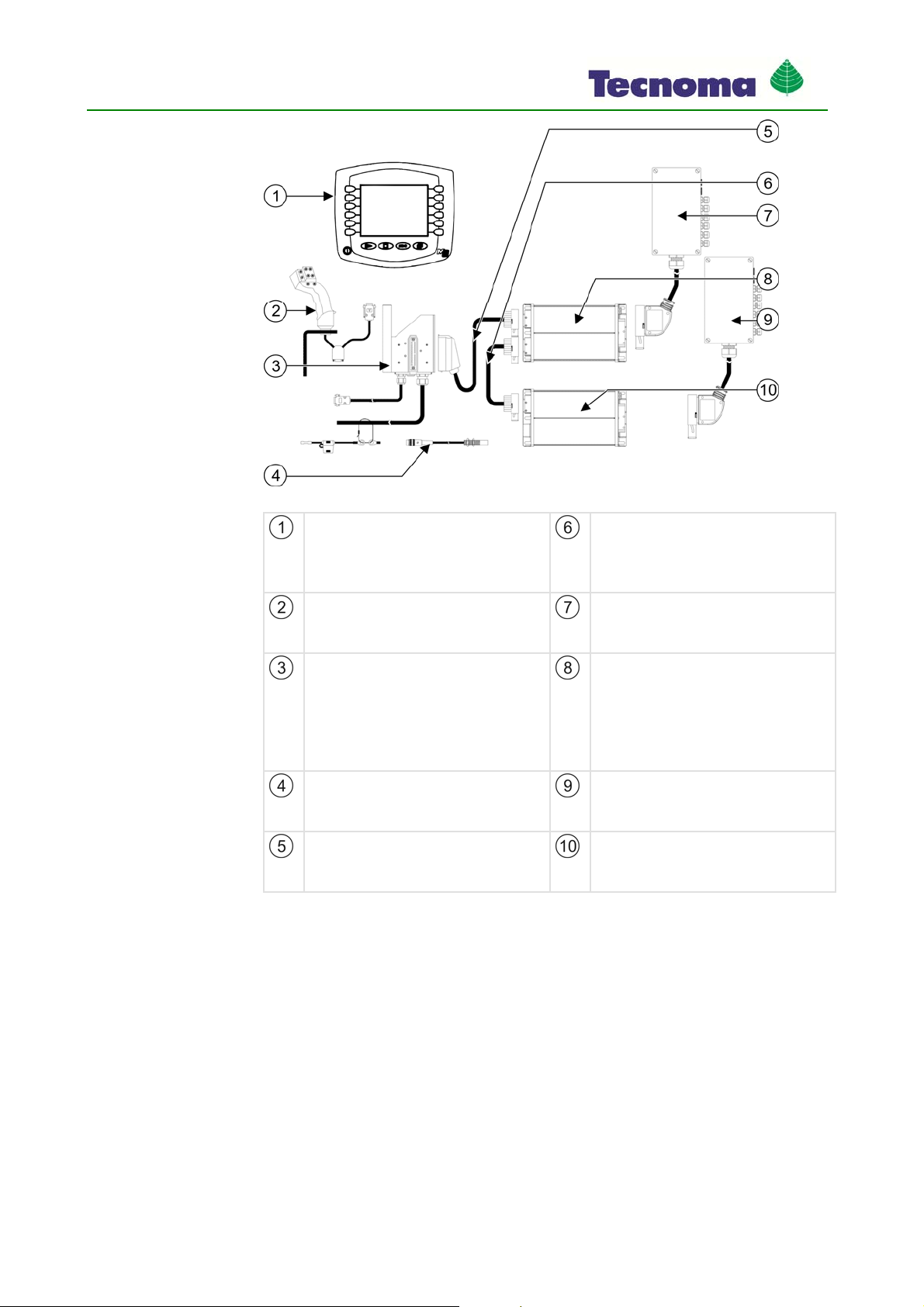
System overview of job computer on a tractor without ISOBUS interface
Terminal
Terminals from Müller-Elektronik Connector cable
Connects job computer F1 and job computer
F2
Different configurations possible
Multi-function joystick
Optional
- Used to operate the field sprayer.
Cable harness and distributor for job
computer F2
Different configurations possible
- Connects the job computers with the tractor.
- Supplies the job computers and the terminal
with voltage.
- Offers the option of connection of a wheel
sensor.
Job computer F2
Slave job computer
Different configurations possible
Wheel sensor Cable harness and distributor for job
computer F1
Different configurations possible
Connection cable for ECO basic equipment
Connection of the job computer sprayer to the
tractor's basic equipment.
Job computer F1
Master job computer
Different configurations possible
Connecting job computer to the basic tractor equipment
For you to operate the field sprayer with the terminal, you must connect the job computer to the
tractor's basic equipment. You need to use different plugs depending on the type of basic equipment
fitted to the tractor.
Tractor with ISOBUS basic equipment
This is how you connect the job computer to the ISOBUS basic equipment:
Tractor is ISOBUS-capable.
Job computer is fitted to the field sprayer.
Field sprayer has been attached to or is trailed by the tractor.
4.2
Procedure

Mounting and installation
17 990267EN ind. A
1. Pull cable from the field sprayer to the ISOBUS basic equipment socket.
2. Unfasten dust protection caps.
3. Insert ISOBUS plug into the tractor's ISOBUS socket and screw in.
4. Connect dust protection caps with one another to protect the sockets from dust.
⇨You have connected the job computer to the basic equipment.
5. Check whether the job computer is correctly connected by starting it up.
Tractor with ECO basic equipment
This is how you connect the job computer to the ECO basic equipment:
Tractor is fitted with basic ECO equipment from Müller-Elektronik.
Job computer is fitted to the field sprayer.
Field sprayer has been attached to or is trailed by the tractor.
1. Pull cable from the field sprayer to the ECO basic equipment socket.
2. Insert the plug of the ECO basic equipment into the socket.
First insert the hook on the tip of the plug into the opening in the socket :
3. Let the plug snap .
⇨You have connected the job computer to the basic equipment.
4. Check whether the job computer is correctly connected by starting it up.
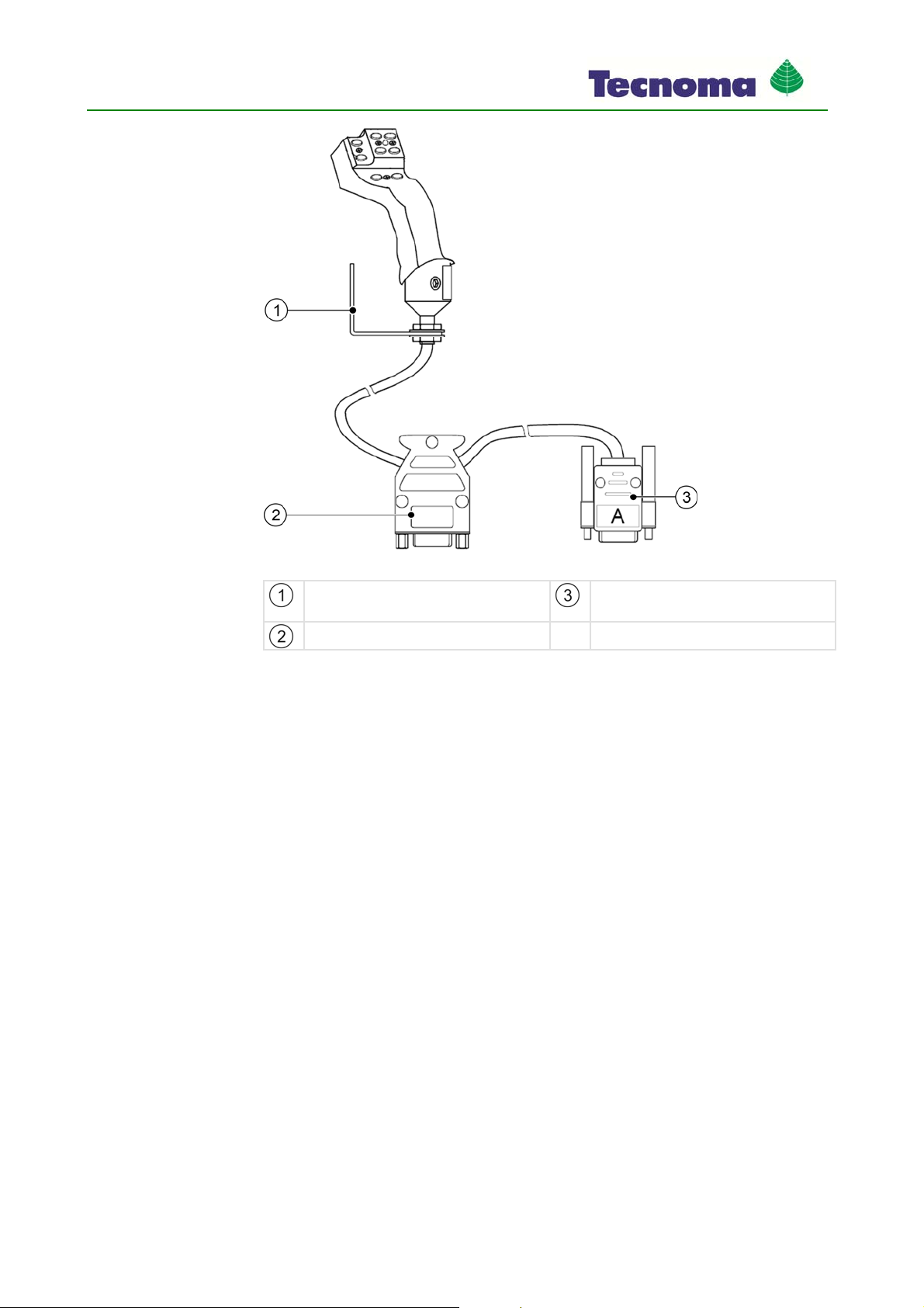
Fitting multi-function joystick (MFG)
The multi-function joystick can additionally be connected to the terminal and is absolutely essential
for operation of the field sprayer.
Procedure
4.3
Mounting and installation
18 990267EN ind. A
Connecting multi-function joystick
Mounting angle
For attachment in the cabin Connector for connection to the terminal
Jack for connection to the basic equipment
You fit the multi-function joystick as follows:
1. Fit the multi-function joystick next to the driver on the right.
2. Plug in the connector of the basic equipment to the jack on the multi-function joystick.
3. Plug in connector A on the multi-function joystick to jack A on the terminal.
⇨The multi-function joystick is connected between the basic equipment and the terminal.
⇨When the terminal is switched on, the LED on the multi-function joystick lights up.
Mounting the gyroscope
The gyroscope is a measuring device to determine the direction changes of the tractor.
To mount the gyroscope you must carry out the following:
▪Mount the bracket on the tractor
Procedure
4.4

Mounting and installation
19 990267EN ind. A
Mounting the bracket for the gyroscope
Bracket Gyroscope in the bracket
Mounting the bracket on the tractor
The bracket on the tractor is used for fastening the gyroscope to the tractor for the duration of work
on the field.
1. Determine the position for mounting the bracket on the tractor.
The bracket must be mounted vertically and without vibration on the rear of the tractor.
Make sure that the connection cable of the gyroscope does not become too taut when fastened
in the bracket.
2. CAUTION! Before drilling a hole, make sure that for drilling you do not damage any
cables.
3. Drill the holes for the screws.
4. Fasten the bracket.
The bracket must be fastened securely to prevent shaking while driving.
4.4.1
Procedure

Mounting and installation
20 990267EN ind. A
Using the gyroscope
1. Fasten the gyroscope into the bracket on the tractor and screw tight with the wing screw.
The side with the TOP-OBEN label must be on the top:
2. After work, fasten the gyroscope into the bracket on the trailer device and screw tight with the
wing screw.
4.4.2
Procedure
Table of contents


