Lilliput PC-7106PRO User manual

Embedded Computer
User Manual

Safety maintenance:
Please maintain your system properly to make sure its service life and reduce
the damage risk.
It should avoid the humidity and extreme temperature when being used.
Avoid prolonged exposure of the unit to direct sunlight or strong
ultraviolet light.
Do not drop the unit or let it be in any place with severe shock / vibration.
Please avoid the collision as the LCD screen is very easy to be scratched.
Do not use any sharp object to touch the screen.
To clean the outside fuselage, please turn off the power, unplug the
power cord, scrub / wipe with slightly damp soft cloth. When cleaning the
screen, please wipe with the lint free soft cloth.
Never attempt to disassemble or repair the machine, otherwise the unit
may be damaged.
Do not place your unit or accessories together with other flammable
liquids, gases, or other explosive materials, to avoid danger.
Please unplug the power plug and remove the built-in battery if long-term
no-use, or thunder weather.

Content
1. Product Description................................................................................................8
1-1 Brief Introduction ...........................................................................................8
1-2 Optional Functions........................................................................................8
1-3 Basic Parameters..........................................................................................9
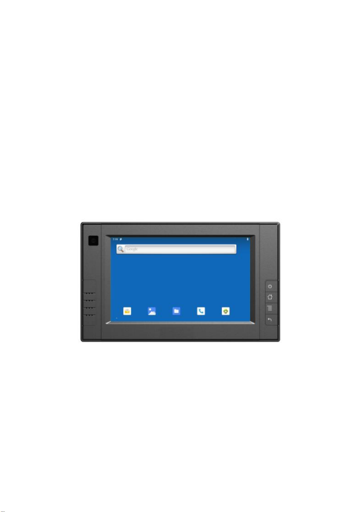
1-4 Structure Function Explanation.................................................................11
2. Extended Cable Definition...................................................................................12
3. Instructions SIM card & TF card.........................................................................13
4. MENU.....................................................................................................................14
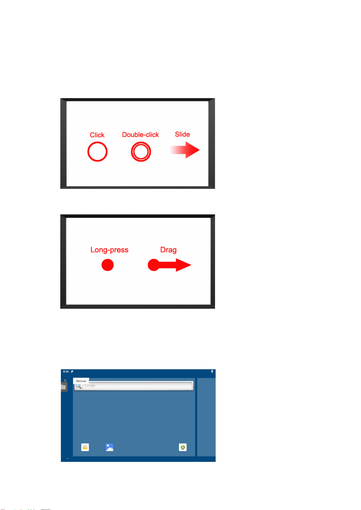
4-1 Gestures .......................................................................................................14
4-2 Delete............................................................................................................14
4-3 Icon bar.........................................................................................................15
4-4 Applied...........................................................................................................16
4-5 Introduction...................................................................................................17
4-5-1 Power On / Off and Dormancy / Wake..........................................17
4-5-2 Manage device power supply.........................................................17
4-5-3 Device is equipped with batteries...................................................17
4-6 ACC Setting Path...........................................................................................20
4-7 Using GPIO....................................................................................................22
4-7-1 GPIO Tail Lines Instruction..............................................................22
4-7-2 GPIO Typical Connection................................................................22
4-7-3 GPIO interface...................................................................................23
5. Accessories............................................................................................................24
6. Trouble Shooting...................................................................................................25

1. Product Description
1-1 Brief Introduction
7" 16:9 Digital touch wide screen, 800×480 physical resolution, with
rich colors;
Comply with IP 64 Waterproof Standard;
Android 9.0 operation system;
Micro SD (TF) card storage, making the data reading reliable and daily
expansion convenient.
Speaker, Microphone
1-2 Optional Functions
GPS (external / built-in)
Wi-Fi 802.11 b/g/n/ac (built-in)
4G (built-in)
Bluetooth 5.0 (built-in)
CAN bus×2
2200mAh Li-ion battery (built-in)

1-3 Basic Parameters
Specifications
CPU
NXP i.MX 8M Mini, ARM® Cortex®-A53
Quad-Core 1.6GHz
GPU
3D GPU (1xshader, OpenGL®ES 2.0) 2D GPU
OS
Android 9.0
RAM+ROM
2GB LPDDR4+16GB Flash
4GB LPDDR4+32GB Flash (optional)
Video Decode
1080p60 (H.265, VP9, H.264, VP8)
Video Encode
1080p60 (H.264)
Sensors
Gyroscope & accelerometer; Compass
DISPLAY
LCD
7 inch IPS, 800x480 resolution, 450 nit
Touch
Capacitive touch screen
INTERFACES
LAN
1000M
GPIO
X 8 (Software freely define input and output)
COM
RS232x4
RS232x3+RS485x1 (optional)
The optional Bluetooth and GPS will each occupy an RS232
port.
SIM Card
X1
SD Card
X1
USB
USB 2.0 Devicesx1,USB 2.0 Host x1
Earphone Jack
3.5mm
OPTIONAL FUNCTIONS
CAN
×2
Cellular Network
3G / 4G
WIFI
IEEE 802.11 a/b/g/n/ac; 2.4GHz / 5GHz
BT
5.0

GPS
Built-in or external
ACC
X1
Microphone
Build-in Microphone
POWER
Power Supply
DC 10-36V (DC 11-36V with built-in battery)
Power
Consumption
≤10W
Battery(optional)
Built-in 2200mAh
OTHERS
Speaker
X1
Dimension
220x132x36.5mm
Weight
740g
Environment
Dust resistance test: IP6x
Water resistance test: IPx4
Operating temperature:-10℃~65℃(14℉~149℉)
0℃~40℃(32℉~104℉)(Built-in battery)
Storage temperature:-20℃~70℃(-4℉~158℉)

1-4 Structure Function Explanation

2. Extended Cable Definition
No.
Item
Specification
1
Convertor
To connect with device cable
2
COM 0 serial port
Bluetooth
3
COM 1 serial port
Used to print debug information
4
COM 2 serial port
Built-in GPS (optional): RS232 or GPS for optional
External GPS (optional): GPS function only
5
COM 3 serial port
RS232 / RS485
6
USB host port
For data transmission
7
LAN port
For network connection
8
Power
Connect with power adapter
9
GPIO port
1
2
3
4
5
GND
commom
GPIO 8
GPIO 7
GPIO 6
6
7
8
9
10
GPIO 5
GPIO 4
GPIO 3
GPIO 2
GPIO 1
10
CANBUS /RS 485
1
2
3
4
5
6
CAN1H
CAN1L
CAN2H
CAN2L
RS485+
RS485-
11
ACC
Connect ACC power

3. Instructions SIM card & TF card
The SIM card, memory card and the card connectors on the device are
precision electronic components. When inserting the SIM card or
memory card into the card connectors, you much insert after aligning
to the position accurately in case of damaging the components. When
removing the SIM card or memory card, please slightly push the upper
edge of the card to loosen the card, then pull it out.
The memory card will get heat after long time working. It is a normal
phenomenon.
If you don’t use SIM card correctly, or cutting off the power or pulling
out the SIM card during the operation, the network will be interrupted
automatically.
Insert the memory card as shown in below picture
Find the location of the SIM card or memory
card slot on the unit, then push the SIM card
or Micro SD card with the part of the metal
contacts outward until it snaps into the
location.
Do not force to Insert the SIM card or memory
card to avoid damaging the card.
Please do NOT insert micro SD card into SIM
card slot improperly, otherwise, the micro SD
will be very difficult to be taken out, or may even be damaged.

4. MENU
4-1 Gestures
Click, Double Click and Slide
Long-press and Drag
4-2 Delete
Long-press the application icon, and drag to the Home screen, then drop to
the recycle lift-up to delete this software.

4-3 Icon bar
Icon
Name
Description
WLAN
Wi-Fi signal connection and status of signal
weakness or strength.
Bluetooth
Bluetooth available
Not disturb
Turn it on and enter do not Disturb mode.
The product is in silent state, no notification is
displayed, and no notification prompt is issued.
Auto rotation
The display is currently rotating automatically
power saving
mode
Power saving mode can be turned on only when
using battery power
NO card
Icon displayed when no SIM card.
Mobile data
Display mobile signal connection status.
Flight Mode
Flight mode status
Position
GPS positioning
Wi-Fi Hotspot
Wi-Fi Hotspot available

4-4 Applied
Scroll up to the “ ” icon in the lower left corner of the screen to see all the
apps on the device
Icon
Name
Description
Phone
Open the dial interface.
E-mail
After you set up your e-mail account, you will be
reminded when there are new e-mails.
Calculator
Turn on the calculator.
Recorder
When the recorder is turned on, it can save the
recording record quickly.
Calendar
In the calendar you can view the date, or you
can add the schedule.
Setting
It can be set up according to individual
requirements
Clock
Check the time and set the alarm, timer and
stopwatch.
Address
book
View the address book and add new contacts.
Picture
The gallery program supports viewing by folder
path.
File
Open to manage files.
Camera
Turn on photographing mode.
Music
Support for playing local and online music.
Ethernet
Ethernet can be managed
Modify static or dynamic IP and proxy Settings
Search
Click to go to Google Search
Browser
Android Web browser

4-5 Introduction
4-5-1 Power On / Off and Dormancy / Wake
Click the power button on the device to open/close the device when
the device goes to sleep (screen saver program) with forced power
outage.
The correct operation of the power key will help ensure the stability of
the system. The device state indicated by the color of the lamp is
displayed, as shown in the following table:
Indicator color
Device Status
Charging and Discharging
Power On/Off
Green light on
Uncharged or Full charged
Power on
Red light on
Charging
Power off or Power on
Red or Green light
blinking
The device is abnormal, please cut off the external power
supply immediately and return it back to the factory for
repair.
4-5-2 Manage device power supply
1. Power on: Press the power button, start the system after running the
LOGO display.
2. Power off: Long press the power button for more than 2 seconds
until the shutdown option pops out, then click the shutdown option.
3. Dormancy device: Automatic sleep, sleep time can be set in
Settings; Press short to enter hibernation mode.
4. Wake up device: Short press the power button to wake up the
sleeping device.
4-5-3 Device is equipped with batteries
a. Rechargeable batteries
Due to transportation, the battery will be partially drained when the
package is delivered to you. Make sure the battery is fully charged on
the first charge.
Please keep dc in charging state when working. The device uses a DC
input power source first, rather than a power source stored in an
internal battery.

b. Check the battery level
During charging, the status bar will display the battery power indicator,
showing the charging percentage.To see the percent charge, slide
down the status bar to see the percent charge.
When the battery is fully charged, the DC input can be disconnected. If
available, use a DC power supply to keep it charged.
c. Check the battery level
If the monitor cannot be continuously charged by dc power, to optimize
the working time of the battery, it is recommended that you do the
following
Turn down the display brightness.
Set a short time to go into sleep mode.
Turn off the monitor when not in use.
Not applicable to the application. To check the battery usage of each
application, the application can be a serious drain on the battery. Not
applicable to the application. To check the battery usage of each
application, the application can be a serious drain on the battery.
Enable CPU power saving mode on the battery Settings page to limit
the maximum CPU performance to save battery power and reduce
device temperature. To get to the battery Settings page, slide down the
status bar in the upper right corner and long press the power-saving
mode button to turn it on.

Turn on the switch after enter the system, as shown in the figure below

4-6 ACC Setting Path
ACC settings located in ACC Settings under the category of System in
the Settings of Android OS. Please refer to Figure 2-1, 2-2 and 2-3:
Clock go to Settings and select "ACC Settings" as shown.

ACC settings as shown in Figure 2-4 & Figure 2-5.
Mark 1: The main switch of the three functions controlled byACC,
namely, light up the screen, close the screen and shut down.
Mark 2: The switch of close screen function controlled by ACC.
Mark 3: Click to pop-up dialog box as shown in Figure 2-6, to edit the
screen off delay time afterACC outage.
Mark 4: The current screen off delay time after ACC outage.
Mark 5: The switch of Trigger to shut down function byACC outage.
Mark 6: Click to pop-up dialog box as shown in Figure 2-7, to edit the
shut down delay time afterACC outage.
Mark 7: The current shut down delay time after ACC outage.

GPIO input
GPIO output
GND
GPIO output
GPIO Input
GND
Peripheral unit
monitor
Figure 2-6 Screen off delay time setting dialog box
Figure 2-7 Shut down delay time setting dialog box
4-7 Using GPIO
4-7-1 GPIO Tail Lines Instruction
Regarding the definition diagram of GPIO interface, please see the details
in Chapter “ 2. Extended Cable Definition ”.
4-7-2 GPIO Typical Connection
The following figure is a typical connection method of GPIO. In order to
ensure the data communicate normally, please connect the GPIO interface
of monitor as shown in the following figure.
GPIO Cable
GPIO Cable
GND

4-7-3 GPIO interface
Double-click“ ” to enter the GPIO interface:
Name: GPIO pin number.
Direction: GPIO state. You can choose GPIO as the input state or output
state.As shown in figure “1”.
Satate: HIGH of high level, LOW of low level
Operation: Read whether the current mode is high or low, displayed in the
status bar.
READ_ALL: GPIO is the state of the level at input.
SET_ALL: GPIO is the state of the level at output.

5. Accessories
Standard accessories:
1. Extended cable 1piece
2. DC12V adapter 1piece
3. Mini USB cable 1piece
4. User manual 1copy
Optional accessories:
1. 75mm VESA rail slot 1piece
2. Mounting bracket 1piece
3. 2200mAh Li-ion battery 1piece
Table of contents
Other Lilliput Desktop manuals
Popular Desktop manuals by other brands

Lenovo
Lenovo ThinkCentre A52 Quick reference guide

Asus
Asus T3-M2NC51PV - T Series - 0 MB RAM user guide

Advantech
Advantech AWS-8248 user manual

Moxa Technologies
Moxa Technologies DA-682A-DPP Series Quick installation guide

HP
HP TouchSmart 600-1200 - Desktop PC Quick setup guide

Control Data
Control Data 3100 Reference manual