TECWELD Sherman digitec DIGITIG 210P User manual

V1.2 19/01/23
USER MANUAL
WELDING RECTIFIER Inverter
DIGITIG 210P
2
WARNING!
Before installing and commissioning, please read these instructions
1. GENERAL
Commissioning and operation of the device can be made only after a careful reading of this handbook.
Due to the continuous development of technical equipment, some of its functions can be modified and operation may differ in detail from the description
in the manual. This is not a device error, but the result of continuous progress and modification work unit.
Damage from improper handling results in a loss of warranty. Any alteration of the rectifier are prohibited and void the warranty.
2. SAFETY
Staff operating the device should have the necessary qualifications entitling them to carry out welding work:
• should have the competence in the field of electric welder MMA welding and gas-shielded,
• know the rules of safety during the operation of the power they are welding equipment and auxiliary equipment powered by electricity,
•know the safety rules when handling and installation of the cylinder of compressed gas (argon)
• know the contents of this manual and use the device for its intended purpose.
WARNING
Welding may endanger the safety of the operator and other persons in the vicinity. Therefore, when welding special precautions must be
taken. Prior to welding, refer to the applicable health and safety regulations in the workplace. During electric welding MMA and TIG has the
following hazards:
•ELECTRIC SHOCK
•ARC NEGATIVE IMPACT ON HUMAN EYES AND SKIN
•PAIRS AND GAS POISONING
•BURNS
•EXPLOSION AND FIRE HAZARDS
•NOISE
Prevention of electric shock:
• a device connected to a technically efficient electrical system in a proper security and effectiveness of neutral (additional fire protection); Check
and properly connect to the network and other devices in the workplace welder,
• current leads off with the mounted unit,
• It does not simultaneously touch the non-insulated part of the electrode holder, the electrode and the workpiece in the device housing,
• Do not use the handles and load wires with damaged insulation,
• under special hazard of electric shock (work in environments with high humidity and closed tanks) to work with the helper supporting the work of
the welder and watchful over the safety, use gloves and clothing with good insulation properties,
• if you notice any irregularities, please contact the competent people to remove them,
• It is forbidden to operate the device with the covers removed.
Preventing negative effects of electric arc on human skin and eyes:
• Use protective clothing (gloves, lab coat, shoes, leather)
• Use protective shields or helmets with properly matched filter,
• Use protective curtains of non-combustible materials, and properly selected colors wall absorbing the harmful radiation.

3
Poisoning prevention vapors and gases evolved at the time of welding of coatings for welding electrodes and evaporation of metals:
• Use ventilation and exhaust installed in limited air exchange.
• Blow fresh air when working in a confined space (tanks)
• Use masks and respirators.
Preventing burns:
• Wear suitable protective clothing and footwear to protect from burns from arc radiation and spatter,
• Avoid contamination of clothing lubricants and oils that may lead to its inflammation
Explosion prevention and fire:
• Do not operate the machine and welding in areas at risk of explosion or fire.
• Welding station should be equipped with fire-fighting equipment,
• Welding station should be located a safe distance from flammable materials.
Preventing negative effects of noise:
• Wear earplugs or other protection against noise
• Warn people about the danger nearby
WARNING!
Do not use the power source for thawing frozen pipes.
Before starting the unit:
• Check the condition of electrical and mechanical connections. It is forbidden to use the handles and the current conductors with damaged
insulation. Inadequate insulation handles and cables current danger
electric shock
• Ensure proper operating conditions, ie. To ensure proper temperature, moisture and ventilation in the workplace. Outdoors closed to protect from
rain,
• Place the charger in a place that allows its easy handling. Persons operating welder should:
• have the power to electric welding electrode welding and TIG,
• know and comply with applicable health and safety regulations when performing welding work,
• use proper, specialized protective equipment: gloves, apron, rubber boots, shield or welding helmet with a suitably selected filter.
• know the contents of this manual welder and operated in accordance with its intended purpose, Repair work may only be carried out after removing
the plug from the wall socket.
When the device is connected to the network is not allowed to touch the bare hand or by any wet clothing elements forming the welding current circuit.
It is forbidden to remove the outer casing when the device is turned on to the network. Any alteration of the rectifier on their own are prohibited and may
constitute a deterioration in security conditions.
All maintenance and repair may only be performed by authorized persons with the conditions applicable to the safety of electrical equipment. Do not
operate the welder in areas at risk of explosion or fire! Welding station should be equipped with fire-fighting equipment, After use the unit's power cord
must be disconnected from the network.
The above risks and the general safety rules is not exhaustive safety of the welder, since it does not take into account the specifics of the workplace.
They are an important complement to bench safety instructions and training and briefings given by supervisory staff.

4
3. GENERAL DESCRIPTION
The device DIGITIG 210P is used for manual welding structural steel coated electrodes (MMA method) and quality steels, copper and its alloys tungsten
inert gas (TIG). This is the inverter device, manufactured with the most technologically advanced components made in IGBT technology. Welding has an
adjustable ARC FORCE and the ability to adjust the frequency of the pulse, fall time and current powypływu gas. It allows control mode and dwutaktu
czterotaktu.
4. SPECIFICATIONS
4.1 welder
power supply AC 230V ± 10% 50Hz
Maximum power consumption MMA 8.2 kVA TIG 7.3 kVA
Rated welding current / cycle MMA: 180 A / 40% TIG 200 A / 40%
Rated voltage of no-load condition 75 V
Maximum current consumption MMA 34 A 30.5 A TIG
network security 16 And
Weight (without accessories) 7.5 kg
dimensions 430 x 168 x 312 mm
Level of security IP21S
4.1.1 range parameter adjustment
ARC FORCE 1 - 10
Post-gas 1 - 10 s
drooping current 0 - 5 s
welding current MMA: A TIG 10-180: 10-200 A
pulse rate 0.2 - 200 Hz
4.2 TIG
handle type T-26
The maximum current carrying capacity 200 A
gas flow 10-20 l / min
arc ignition Contactless (HF)
Length 4 m
Duty cycle
Duty cycle is based on a period of 10 minutes. 40% duty cycle indicates that after 4 minutes of operation of the device is required for a 6-minute break.
Duty cycle of 100% means that the machine can operate continuously without interruption.
Attention! Heating test was carried out in the ambient air temperature. Duty cycle at 20 ° C was determined by simulation.
Level of security
IP specifies the degree to which the device is resistant to entering of solid impurities and water. IP21S means that the device is suitable for use in
confined spaces and is not suitable for use in the rain.
5
5. CONSTRUCTION AND OPERATION
The basis for the construction of the power conversion electronics welders are made in IGBT technology for working in the frequency range above
200 kHz.
The principle consists of a single-phase rectified voltage to the power supply voltage, conversion of the resulting DC voltage to a square
wave high frequency voltage transformation in the range required by the welding process and re-erection of the resulting voltage on the DC voltage.
6. CONNECTION TO THE MAINS 6. CONNECTION TO THE MAINS
1. A device to be used only in a single-phase, three-wire, with earthed neutral.
2. The inverter units DIGITIG 210P are adapted to cooperate with a network of 230V 50 Hz fused 16A by time-delayed action. Power supply should
be stable, with no voltage drops
3. The device is equipped with a power cord. Before connecting, make sure the power switch (15) is in the OFF position (off).
7. PREPARING THE APPLIANCE FOR OPERATION
For storage or transport devices in freezing temperatures before the start of work to bring the device to an appropriate temperature
!!!
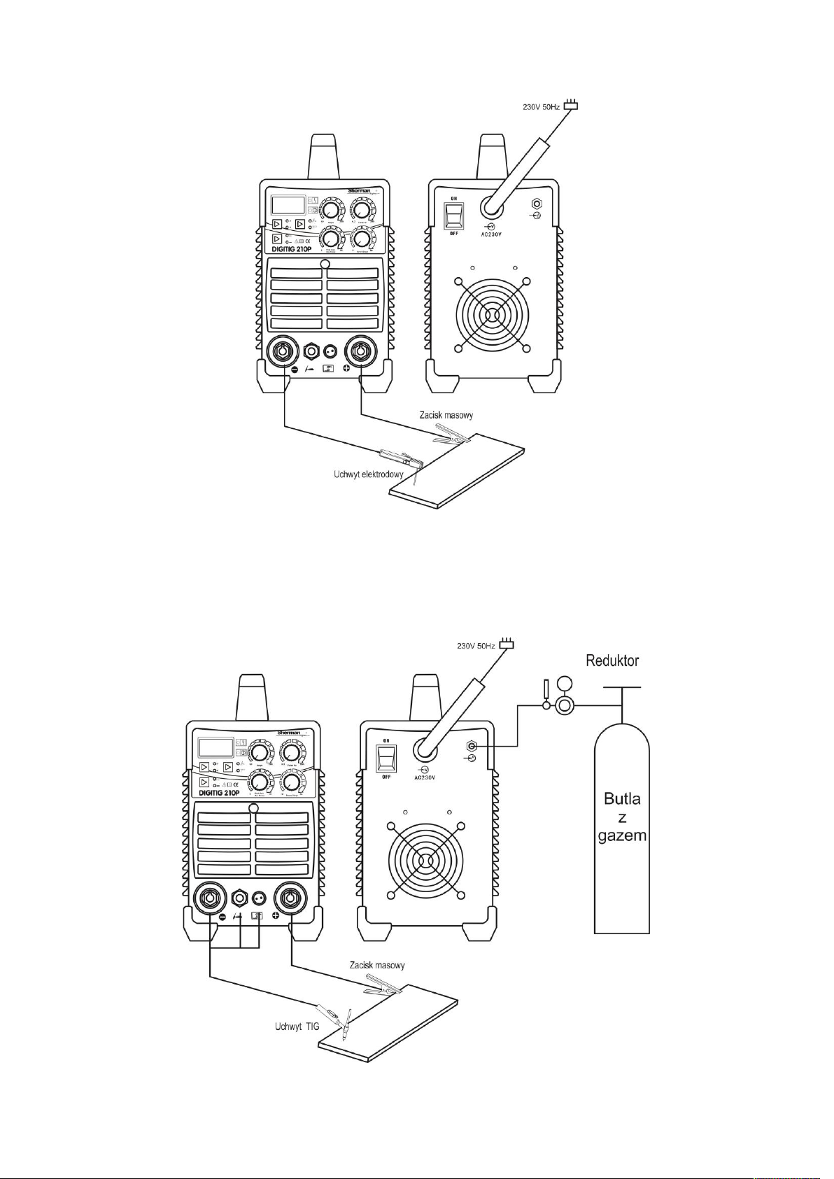
7.1 MMA
Welding the wire ends to terminals (8) and (9) located on the front panel so that the electrode holder was appropriate for the electrode pole. The polarity
of the wiring depends on the type of welding electrodes used and is given on the electrode packaging. Ground cable terminal must be carefully mounted
on a welded material. Plug the device into a power outlet 230V 50Hz.
6
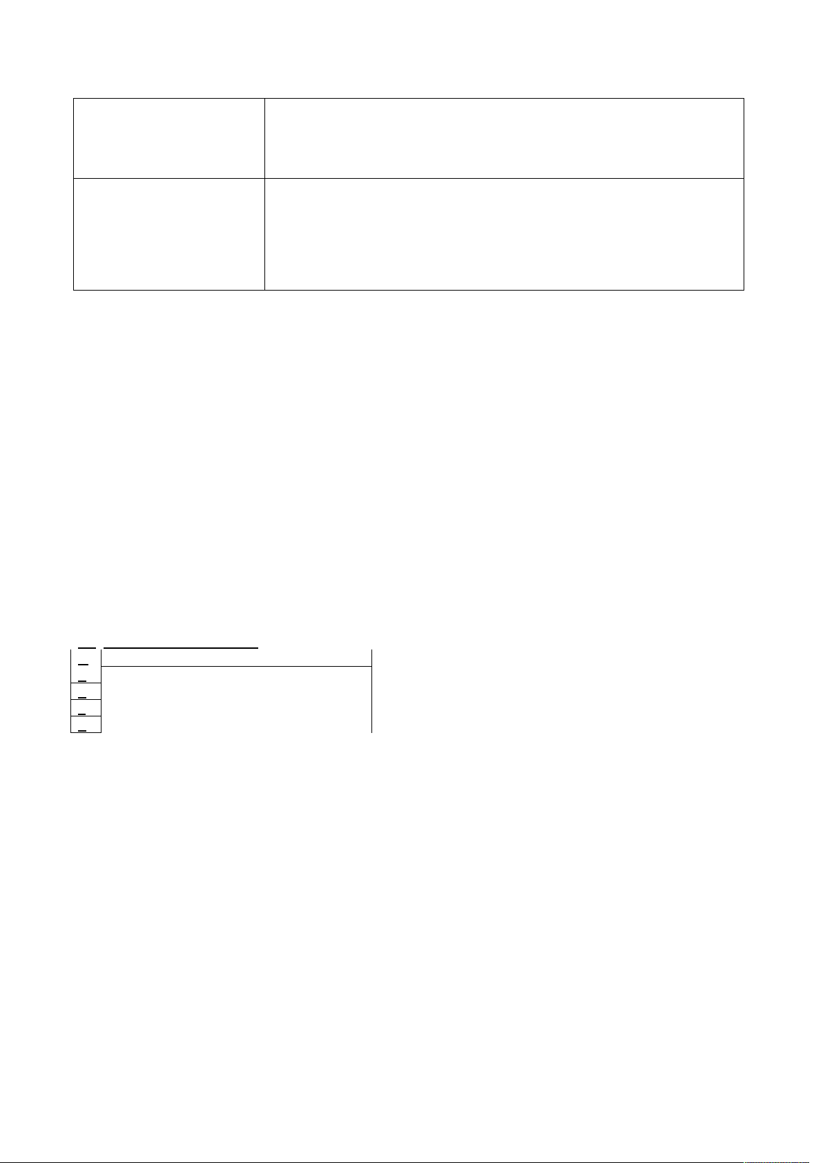
7.2 TIG
Current terminal holder should be connected to the negative pole (9), plug control handle carefully screwed into the socket (11) and a gas connection to
the socket (10). Gas conduit from the regulator, lead and attach to the gas nozzle (17) arranged on the rear wall of the housing. The positive pole of the
source (8) connected to the work piece by means of a wire with a clamp. Plug the device into a power outlet 230V 50Hz.

7
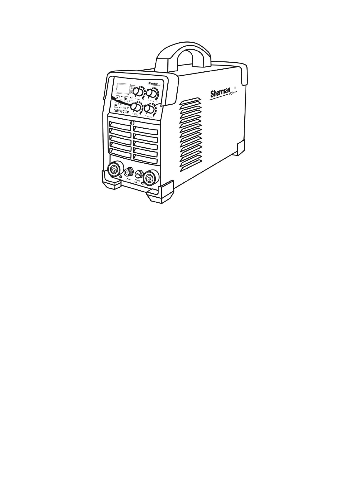
8. FUNCTIONAL DESCRIPTION switches and DIAL
1. Display
2. The LED power
3. indication of improper operation
4. Welding current regulator
5. The pulse frequency adjustment knob
6. The adjustment knob downslope
7. The knob functions ARC FORCE (MMA) / powypływu gas
(TIG)
8. Slot "+"
9. Nest "-"
10. The seat of protective gas
11. Socket control TIG
Button 12. pulsator
13. Key control the source (two-stroke engine /
czterotakt)
14. Key selection of welding method
15. Main switch
16. Power Cord
17. nipple shield gas connection
18. fan
8.1. Protection against overheating
IGBT module is protected against overheating by installing protective welding machine which turns off the power. When the temperature of the welding
device is too high, the security disconnects the welding current and the LED will overheat indicator (2). After a few minutes, the cooling device to a
temperature permitting continued operation. There should at that time interrupt the power supply, since the continuously operating fan cools the heat
sinks inside the unit to more quickly reduce the temperature. After falling temperature will automatically reset the circuit breaker. After restarting, be sure
to limit the welding parameters for further continuous operation.
9. PARAMETERS
9.1 MMA
During the MMA welding can adjust the welding current and the function button ARC FORCE method of welding (14) to select the method
of MMA ( ). Knob (4) to the desired
value of the welding current and the knob (7) to FORCE function value ARC.
welding current
Range: 10 - 180A

8
ARC FORCE
ARC FORCE allows the arc. Shortening the length of the arc is accompanied by an increase in the welding current, which results in stabilizing the arc.
Decreasing the value will give a soft arc and a smaller depth of penetration, while increasing the value results in deeper penetration and the possibility of
short-arc welding. When you set a high value functions ARC FORCE You can be welded while maintaining the minimum arc length and a high speed short-arc welding. When you set a high value functions ARC FORCE You can be welded while maintaining the minimum arc length and a high speed short-arc welding. When you set a high value functions ARC FORCE You can be welded while maintaining the minimum arc length and a high speed
electrode melting range: 0 - 10
9.2 TIG
During TIG welding, it is possible to control the operation mode selection source (two-stroke engine / czterotakt), the choice of working with or without
the pulsator of the pulsator and the control of the welding current, pulse frequency, time and downslope time powypływu gas.
Button to choose the method of welding (14) to select the method (TIG ). Press (13) select
dwutaktu (2T) or czterotaktu (4T) and the button (12) choose to work with pulsator ( ) Or without the pulsator (
) .
Knob (4) to the desired value of the welding current, the knob (5) to set the pulse frequency (only when the pulsator), the knob (6) to set the fall time of
the current and the knob (7) Time powypływu gas.
welding current
Range: 10 - 200A
Time downslope - fall time of the welding current value set to zero and the current value of the crater. Time downslope - fall time of the welding current value set to zero and the current value of the crater. Time downslope - fall time of the welding current value set to zero and the current value of the crater.
Range: 0 - 5s
pulse rate - the frequency with which the value of a pulse of current between the welding current and the current base. pulse rate - the frequency with which the value of a pulse of current between the welding current and the current base.
Range: 0.2 - 200Hz
Time powypływu gas - the time of extinction of the arc to close the gas valve in order to shield the solidifying weld pool from air and for cooling the Time powypływu gas - the time of extinction of the arc to close the gas valve in order to shield the solidifying weld pool from air and for cooling the Time powypływu gas - the time of extinction of the arc to close the gas valve in order to shield the solidifying weld pool from air and for cooling the
tungsten electrode. Too short time powypływu may result in oxidation of the weld. When welding in TIG mode, the AC (alternating current) time should
be longer. Range: 0 - 10s
2T / 4T
Welder during TIG welding can be controlled in the mode dwutaktu and czterotaktu. Dwutaktu mode by pressing the button on the handle and the
welding arc is struck should be carried out with the button pressed. Releasing the button on the handle will complete the welding process. In czterotaktu
mode, press the button on the handle of the burner and ignite the arc. After the correct arc is lit button can be released and welding lead to the slow
button. To complete the welding press and release the button on the handle.
10. WELDING coated electrodes (MMA)
10.1. initiation arc
Initiation arc welding coated electrode is to touch the electrode to the workpiece, and short rubbed isolation. For initiation of the arc electrode wherein the
sheath forms a non-conductive when solidified slag to be pre-clean the tip of the electrode by repeatedly impact against a hard surface until the metal in
contact with the work piece.
11. WELDING tungsten inert gas (TIG)
11.1 Initiation and maintenance of the arc welding process
DIGITIG device 210P is equipped with an ionizer that allows contactless arc ignition.

9
To ignite the arc mode dwutaktu must approach the electrode to the workpiece at a distance of a few millimeters, and press the button on the handle of
the torch. After the correct initiation of arc welding lead the button pressed. Releasing the handle causes us to start phase downslope and end of the
welding process.
To ignite the arc mode dwutaktu must approach the electrode to the workpiece at the distance of 2 millimeters and press the button to turn on the torch
handle ionizer. If within five seconds will not arc ignition, it will shut off automatically, and lights up the LED (18). To re-enable ionizer release button in
the handle, wait until LED (11) and press it again. After the correct initiation of arc welding lead the button pressed. Releasing the button on the handle
causes the start of the current phase of descent and ending the welding process.
To ignite the arc mode czterotaktu must approach the electrode to the workpiece at the distance of 2 millimeters and press the button on the handle of
the torch to turn the ionizer. If within five seconds will not arc ignition, it will shut off automatically, and lights up the LED (18). To re-enable ionizer
release button in the handle, wait until LED (11) and press it again. After the correct arc is lit button can be released and welding lead to the slow button.
To complete the welding press and release the button on the handle.
ATTENTION !! Do not turn on the button at a distance greater than 2 mm from the work piece. Do not touch the electrode while pressing the
button on the handle. Ionizer high voltage and the voltage in no-load condition occurring when the electrode can cause electrical shock.
12. Before calling service,
In the event of malfunction of the unit, before sending welding for service, check the list of basic failures and try to remove them yourself.
Repair work may only be carried out after removing the plug from the wall socket.
Attention! The device is not sealed, and the user can remove the cover of the welding device in order to remove minor breakdowns.
symptoms Remedy
The control panel is not lit, the fan
does not work, no output
1. Make sure the switch is in the ON position
2. Check the security on the network connection and
3. Remove the cover and check the connection of all electrical plug inside the device
The control panel lights up, the fan
does not work, no output voltage.
1. Verify that the device has not been connected to the higher voltage. If so, connect to 230V
and turn again
2. The supply voltage is unstable and turns on the overvoltage protection. Turn off device for 2-3
minutes and then back
3. Short on and off switch may have been activated overvoltage protection. Turn off device for 2-3
minutes and then back
4. There was other damage requiring repair by an authorized service
The control panel lights up, the fan is
working, problems with arc is started
1. Check TIG replace wear parts, if they are used
The control panel lights up, the fan is
running, no strikes arc welder
1. Check the correct terminals and the electrical conductivity of the electrode wire and the mass
2. Check the connection of TIG torch to the device, pay attention to whether the socket pins are not
broken or jam.
3. Unscrew the TIG torch handle and check that the switch in the handle is OK
The control panel is lit, the fan operates,
lights up the LED (2) 1. The device is overheated. Wait a few minutes. After the indicator goes out to
continue welding.
10
Unsatisfactory quality of the weld MMA
electrode sticks to the work piece
1. Check the polarity of the welding wire
2. Check that the electrode is not wet. Replace the electrode.
3. The welder is supplied from the generator or by a long extension cord diameter is too small
cable. Connect directly to the mains
Unsatisfactory quality of the weld
TIG welding
1. Replace consumables. Change the tungsten electrode or the gas cylinder for higher quality
materials
2. Check that the shielding gas flowing at the proper intensity
3. Check the gas hose, improve the connection hose with quick connectors, and status
4. Check regulator przybutlowy.
13. OPERATION MANUAL
Operation of the device DIGITIG 210P should take place in an atmosphere free of corrosive components and dusty. Do not place the device in dusty,
near the working grinders, etc. Dust and pollution control boards metallic filings, wires and connections inside the unit may cause an electrical short, and
consequently damage to the welding machine.
Avoid use in environments with high humidity, especially in situations of occurrence of dew on the metal parts.
If there is dew on the metal parts, for example. After entering the cold equipment into a warm room, wait until the dew disappears. It is recommended
that in the event of welding operation outdoor place it under a roof to protect against adverse weather conditions.
DIGITIG 210P device should be operated under the following conditions:
-changes in the effective value of the supply voltage is not greater than 10%
- ambient temperature of from -10 ° C to + 40 ° C
- Atmospheric pressure 860 to 1060 hPa
- relative humidity of the atmosphere is not more than 80%
- height above sea level to 1000m
You k with consumable parts TIG torch T 26: You k with consumable parts TIG torch T 26: You k with consumable parts TIG torch T 26: You k with consumable parts TIG torch T 26:
lp Name
1 tungsten electrode 1 tungsten electrode
2 Compression sleeve T-26 2 Compression sleeve T-26
3 The connector current T-26 3 The connector current T-26
4 Gas nozzle T-26 4 Gas nozzle T-26
For a full list of consumables and spare parts is available on the website and in the company www.tecweld.pl TECWELD. There is a possibility of direct
purchase of these parts.
14. MAINTENANCE INSTRUCTIONS
As part of the everyday operation of the welder must be kept clean, check the connection status and the status of external electrical wires and cables.
Regularly replace consumables.
Periodically clean the inside of the device by purging with compressed air to remove dust and chips from metallic plates, and the control wires and
electrical connections. Not less than once every six months should be a general review of the status and electrical connections, in particular:
- state of shock protection
- the insulation
- the state security
- the operation of the cooling system
Damage resulting from the welding operation in unsuitable conditions and failure of recommendations for maintenance are not covered by
warranty repairs.

11
15. INSTRUCTION STORAGE AND TRANSPORT
The device should be stored at -10 ° C to + 40 ° C and relative humidity 80% free of corrosive fumes and dusts. Transportation of packaged devices
should be covered means of transport. For transport the packaged unit must be secured against slipping and ensure the correct position.
16. SPECIFICATIONS SET
1. Source DIGITIG 210P 1 piece.
2. Holder for TIG welding 1 piece.
3. Earth cable with a clamp 1 piece.
4. Manual 1 piece.
5. Packaging 1 piece.
17. ELECTRIC SCHEME
12
18. GUARANTEE
Guarantee granted for a period of 12 months for business entities but excluding claims related to or guarantee of 24 months for the consumer
from the date of sale.
The guarantee will be respected by the advertiser after the presentation of proof of purchase (invoice or receipt) and warranty card inscribed
with the product name, serial number, date of sale and point of sale bearing the stamp.
In the case of warranty repair should contact TECWELD, which will arrange the reception device by courier. Consignments sent in a different
way at the expense of the company TECWELD will not be accepted!
Welder should be provided with the welding torch. Complaints device without the torch will not be considered.
The device transmitted to the complaint must be packed in the original carton, and protected by Styrofoam original fittings. TECWELD
company is not liable for damage caused by a welder during transport.
If you wish to discard this product, do not throw it with general household waste. According to the WEEE
Directive (Directive 2002/96 / EC) in force in the European Union for used electrical and electronic
equipment must be used methods of utilization.
In Poland, in accordance with the provisions of the Act of July 1, 2005. Waste electrical and electronic
equipment is prohibited to place together with other wastes of used equipment marked with crossed out
wheeled bin symbol.
The user who wishes to discard this product, it is obliged to return waste electrical and electronic equipment to a used equipment collection
point. Collection points are conducted, among others, by wholesalers and retailers of equipment and the municipal organizational units engaged
in waste collection.
These legal obligations have been introduced to reduce the amount of waste generated from waste electrical and electronic equipment and to
ensure an adequate level of collection, recovery and recycling of used equipment. Proper implementation of these duties is important especially
when the waste equipment contains hazardous components which have a particularly negative impact on the environment and human health.
TECWELD Peter Polak branch:
41-943 Piekary Slaskie Street. Emerald 21/3/6 41-909 Bytom ul. 3 Cross Tel. (+48 32) 38-69-428, fax (+48
32) 38-69-434 e-mail: [email protected] , www.tecwel.pl

DECLARATION OF CONFORMITY
01 / DIGITIG210P / 2018
Manufacturer's authorized representative:
TECWELD Peter Polak
41-943 Piekary Slaskie Street.
Emerald 21/3/6
branch:
41-909 Bytom ul. 3
Cross POLAND
Declare that the said product:
inverter welder
Trade name: DIGITIG 210P
Type: TIG 200P
Manufacturer's trademark:
to which this declaration relates complies with the following directives of the European Union and
national provisions implementing the Directive:
LVD Low Voltage Directive 2014/35 / EU
EMC Electromagnetic Compatibility Directive 2014/30 / EU
II RoHS Directive 2011/65 / EU
and is compliant with the following standards:
BS EN 60974-1: 2013-04 Arc welding equipment - Part 1: Welding power sources, BS EN 60974-1: 2013-04 Arc welding equipment - Part 1: Welding power sources,
EN 60974-10: 2014-12 Arc welding equipment - Part 10: Requirements EN 60974-10: 2014-12 Arc welding equipment - Part 10: Requirements
electromagnetic compatibility (EMC)
BS EN 50581: 2013-03 Technical documentation assessment of electrical and electronic products BS EN 50581: 2013-03 Technical documentation assessment of electrical and electronic products
taking into account the restriction of the use of the substance
dangerous.
Year affix the CE mark on the device: 2017
Bytom, dn. 05/01/2018 Peter Polak
(Signature of authorized person)
Table of contents
Popular Welding System manuals by other brands

liquidarc
liquidarc Maxmig 210i operating manual

Grizzly
Grizzly H8153 Replacement parts

Lincoln Electric
Lincoln Electric FlexCool 35 Operator's manual

Lincoln Electric
Lincoln Electric POWERTEC 305C PRO Operator's manual

Cornwell Tools
Cornwell Tools MMWMGS250 owner's manual

Lincoln Electric
Lincoln Electric SAF-FRO DIGISTEEL III 320C Safety Instructions for Operation and Maintenance


THERMACUT
THERMACUT EX-TRAFIRE 55SD Operator's manual

Tweco
Tweco ULTRAFEED VAF-4 Service manual

Draper
Draper MW130TA instructions

Cebora
Cebora PLASMA PROF 163 ACC instruction manual

Lincoln Electric
Lincoln Electric Magnum PRO 175L Operator's manual

Lincoln Global
Lincoln Global Century FC-90 Operator's manual