Tekk International XV-100 Series User manual
XV-100 / XU-100 Portable Radio Manual
* This Service manual is subject to change according to improvement of XV-100 / XU-100 Portable
Radio without notice.

2
* Version #2 (2008-12-05)
----- Table of Contents -----
1. XV/XU-100 Features ------------ 3
2. Components of XV/XU-Series Radio ------------ 6
3. Appearance of XV/XU-Series Radio ------------ 7
4. Basic Operation of XV/XU Series Radio ------------ 8
5. Operating XU/XV-100 RADIO ------------ 11
6. Operating Instructions of XV/XU Series Radio ------------ 15
7. Precautions ------------ 26
8. Safety Notes ------------ 28
9. Specification ------------ 30
9.1 XV-100 ------------ 31
9.2 XV-100 ------------ 32

3
1. XV/XU-100 Features
The features of XV/XU-100 are various as below. XV/XU-100 can used under tough industrial
environments as well as public places. XV/XU-100 series have following functions:
z128 channels and 16 groups are selectable
zCall guard squelch of standardized CTCSS(52) / DCS(104), Invert DCS(104)
zBuilt-in Scrambler
zBuilt-in Compander
zDual Tone Modulation Frequency (DTMF)
zNormal scanning / Priority scanning
zVOX(Voice Operated Transmit)
zIdentification origination(2 Tone and 5 Tone)
zBCL(Busy Channel Lock)/BCLO(Busy Channel Lock Out)
zTime-Out Timer (TOT)
zChannel Spacing Only 12.5KHz
zHigh/Low Power Switching
zSelectable Squelch Level(0~4)
zMonitor
zLone Worker
zHigh-Quality Audio Output
zPLL synthesizer method
zDC+3.7V 1,800mAH rechargeable Li-ion employment quantity battery use
zAdvanced Speaker Protection technology
zRemote Radio Stun / Kill / Revive (Use 5 tone)
zVarious Parameters and PC downloading methods
zPC Tuning

4
1) Numeric LCD Windows
Numeric LCD Windows enable to represent any kind of expression on LCD Display.
2) Built-in Scrambler
Maintaining private and secure communications is increasingly important, with potentially sensitive
information flowing back and forth. The XV/XU-100 Scrambler feature provides enhanced security for
your important public safety and private security communications.
3) Lone Worker
The feature provides added security and safety for individuals who work remotely from their team.
Should a user not respond to a regular warning tone then a defined emergency procedure is activated.
4) Powerful Audio Output
XV/XU-1000 Voice compander audio enhancement and powerful 1W Speaker ensure superb clear,
crisp sound, even in noisy environments.
5) Caller ID (Paging Feature)
XV/XU-1000 have a Caller ID Function that is usually used in the TRS Radio to maximize
communication efficiency and convenience. The caller’s ID is displayed on the right bottom on screen.
6) Power Output Setting Time-out Timer
Programmable power levels provide one of two settings(High/Low) for each of the channels so the
feature allows for more efficient use of channels by radio can be tailored for mixed transmit range
requirements. Output levels can be programmed at 5W/2W on VHF and 4W/2W on UHF.
7) Selectable Squelch Level (0~4)
Helps minimize interference from undesired signals and helps weak signals be heard.
8) 512 Channels and 16 Groups Selectable
Users can use various tones with 53 CTCSS and 104 DCS 512 channels can be divided into 16
groups so that users can make group for other users and page each group.
9) Multi-functional Ear/MIC Jack
With multi-functional Ear/MIC Jack, it is possible to be used together with various accessories.
10) Cloning
For compatibility with current models of TEKK, the data of those models (such as channels, tones, 5-

5
tone ID, etc.) are cloned to another radio with Cloning cable. .
11) Voice Operated Transmit(VOX)
Enjoy the convenience of hands-free operation when used with optional accessories.
12) PC Programming and Tuning
Radio parameter programming and tuning can be accomplished via the accessory connector from a
PC-compatible computer without ever having to open the radio to save both time and expense
(requires optional programming JIG and software)
13) Flash Memory Advantage
Flash memory permits updates, advanced feature sets and system architectural changes to be made
electronically without ever opening the unit. This means fast changes for the system operator and less
down time for users.
1.1 Part Number Breakdown
The following is a breakdown of the part number used to identify this transceiver
XU – 100
Enhanced
OrExtreme TEKKInternationalInc
RadioVersionNO
V : VHF Portable Radio
U:UHFPortableRadio
Model History Table
Model Name Frequency Range RF Power Channel Spacing Remark
XV-100 140~170MHz 2Watt 12.5 KHz
XU-100 440~470MHz 2Watt 12.5 KHz

6
2. Components of XV/XU-Series Radio
* Components could be changed by buyer request.
Figure 1-1) standard components of XV/XU series Radio
7
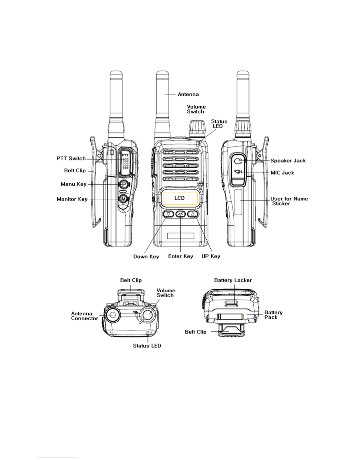
3. Appearance of XV/XU-Series Radio
Figure 3-1) Appearance of XV/XU-100 Series Radio
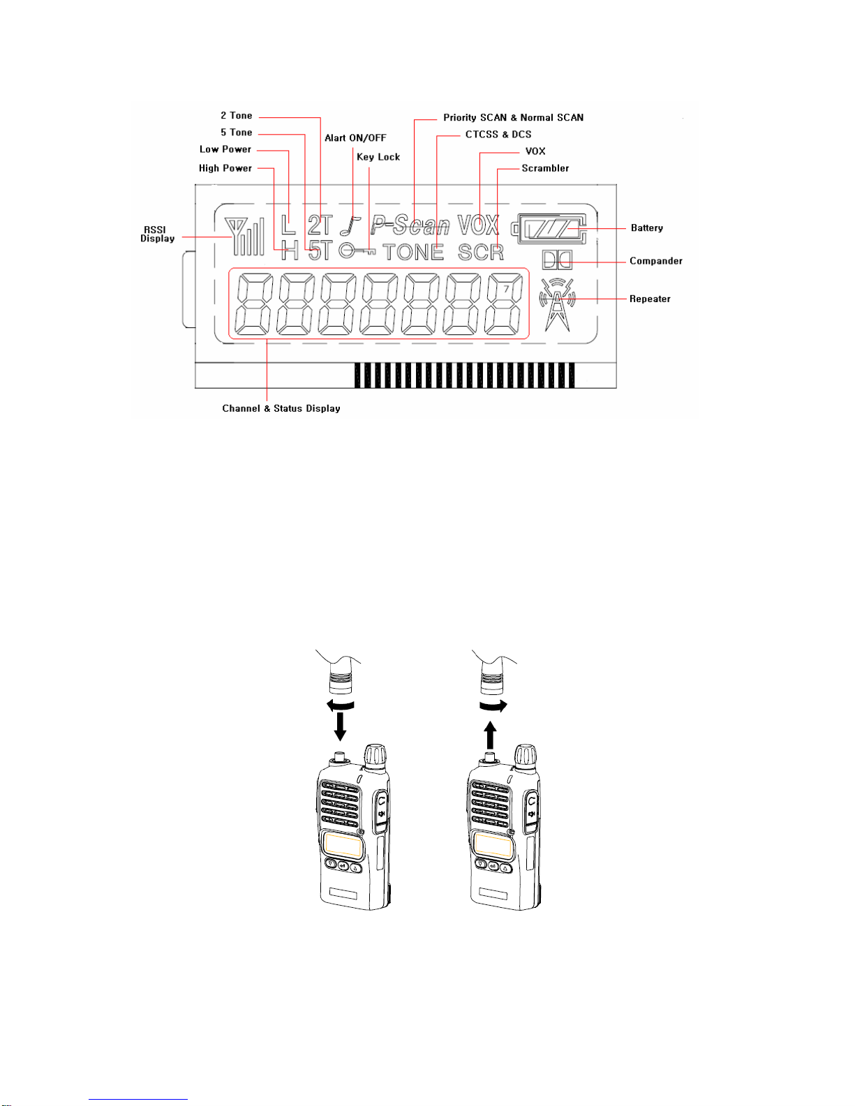
8
Figure 3-2) XV/XU-100 Series LCD Indication
4. Basic Operation of XV/XU Series Radio
Pease read this manual carefully before using XV/XU series Radio.
This manual contains important information about using Radio.
4.1 Installation and Removing the Antenna
To install the antenna, insert the antenna into antenna connector and screw the antenna clockwise.
To remove the antenna, screw the antenna counter clockwise.
Figure 4-1) Installation and Removing the Antenna
9
When installation of the antenna, giving a strong pressure to the Radio
or pulling the antenna with a strong power from the Radio can make a
damage on the antenna connector, which may cause the Radio to have
a critical problem.
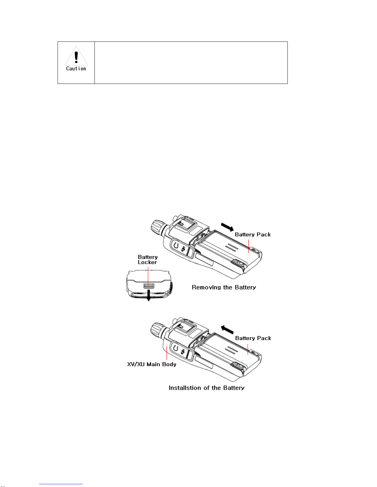
4.2 Installation and Removing the Battery
4.2.1 Installation of the battery
To install battery, slide up the battery towards the top of the radio until battery latch is locked.
4.2.2 Removing the Battery
- Slide the battery latch located on the bottom of radio to the open position as shown in
Figure 4-2.
-The battery is removed by pressing it against and sliding it towards the bottom of the radio
Figure 4-2) Installation and Removing the Battery

10
4.3 Installation and Removing the Belt Clip
- To attach belt clip to radio, align belt clip rails with the grooves in radio and slide the belt clip
onto the mounting rails until it latches into place.
- To remove belt clip from radio, push up on tab of belt clip with flat bladed screwdriver and at the
same time, slide the belt clip towards the top of Radio (Figure4-3).
Figure 4-3) Installation and Removing the Belt Clip
4.4 Accessory connector
Accessory connector is used to connect external speaker/Mic, and headset, etc.
Please close the cover when nothing is connected.
Figure 4-4) Accessory connector

11
5. Operating XU/XV-100 RADIO
5.1 On/Off/Volume Control
Turns the radio on and off and adjusts audio volume level.
5.2 PTT Button(Push-To-Talk Button)
Radio transmission button.
5.3 Menu Button(P, Program Menu Button)
Enter into Menu mode by pressing the Menu button (P) for 2 seconds.
The sequence of menu mode is as follows.
→ → → →
Compander → Change Group → ID → Scramble → Squelch
→ → →
→ KEY Sound → VOX → Lone Worker
5.4 Monitor Button(M)
The monitor mode is enabled and disabled by pressing the Monitor button (M) on the side.
Normal Mode : During pressing the (M) button for about 2 seconds, it is possible to check the
receiving status.
Continuous Mode : During pressing the (M) button for more than 2 seconds, the Radio will make a
“Beep” tone, which means the monitor function is maintained and if you press the (M) button again,
the monitor function will be released.
5.5 Emergency Button
In case of emergency situation, if you press the Emergency button, a siren sound will be heard
through the speaker in the Radio and the Radio will transmit the emergency signal to the party
through the emergency channel.

12
5.6 Channel Buttons(▼,▲)
Channel Buttons(▼,▲) have 3 functions as shown in following.
①Channel buttons(▼,▲) are to change channels.
②Channel buttons(▼,▲) are to select menu at menu mode.
③Channel buttons(▼,▲) are to change transmission power. By pressing Up button(▲) while
PTT button is being pressed, the user can select ”H”(High Power), or by pressing Down
button(▼), the user can select ”L”(Low Power).
5.7 Accessory Connector
The Accessory Connector is used when using an external speaker microphone or doing PC
programming or making the Cloning or using as a Repeater.
5.8 RX /TX Led
This LED is a lamp indicating the current status of the Radio and please refer to the below contents.
① RX : Red Lamp
② TX : Green Lamp
③ CTCSS, DCS Error : Green Blinks.
④ Low Battery: Red Blinks With “beep” sound.
5. Charging the Battery
5.1 Safety Notes
1) The radio of XV/XU series receives power from high-performance Li-ion battery
(XSB-1800). XSB-2400 Battery is safe of high performance and highly reliable, and could be
charged very fast. XSB-2400 Battery has been designed suitably only for the charger of Tekk
(WLB-100).
The charging of the enclosed Radio on the other maker’s charger will
cause a damage on the battery and also, will cause a trouble on the
Radio.
2) Please charge the battery before using the radio for best performance and safety.
3) When you charge the battery that is installed in the Radio, please turn off the radio first to charge
the battery.

13
The continuous rapid discharge (for example, when making a short circuit
on the ‘+’ terminal of battery by a metal substance) may make a fatal
defect and the battery can be exploded. Also, it can cause a fire.
4) Using the correct battery will improve the efficiency and safety.
5.2 The Time of Charging
Low battery voltage will make the radio less coverage and also make the performance worse. Please
charge the battery in case of following:
When you think performance of the radio becomes lower
When the red lamp on RX/TX Led blinks (every 0.5 second) during transmission or reception
When the battery icon blinks
4) When “beep” sound is generated while the radio is in use.
Figure 5-1) XV/XU-100 Charging the Battery
14
5.3 How to Charge
1) Plug the DC-100 charger into the electricity power outlet.
2) When charging the Radio with the battery installed, please turn off the power of the Radio
and place the Radio on the charger (The charger has a slide slot.).
3) After completion of the charging, the green LED on the charger will light. However, please
continue the charging for 30 more minutes for the complete full charge.
status LED indication status LED indication
During charging Red LED lights. Detecting error Red LED is off.
After charging Green LED lights. When charging Green LED lights
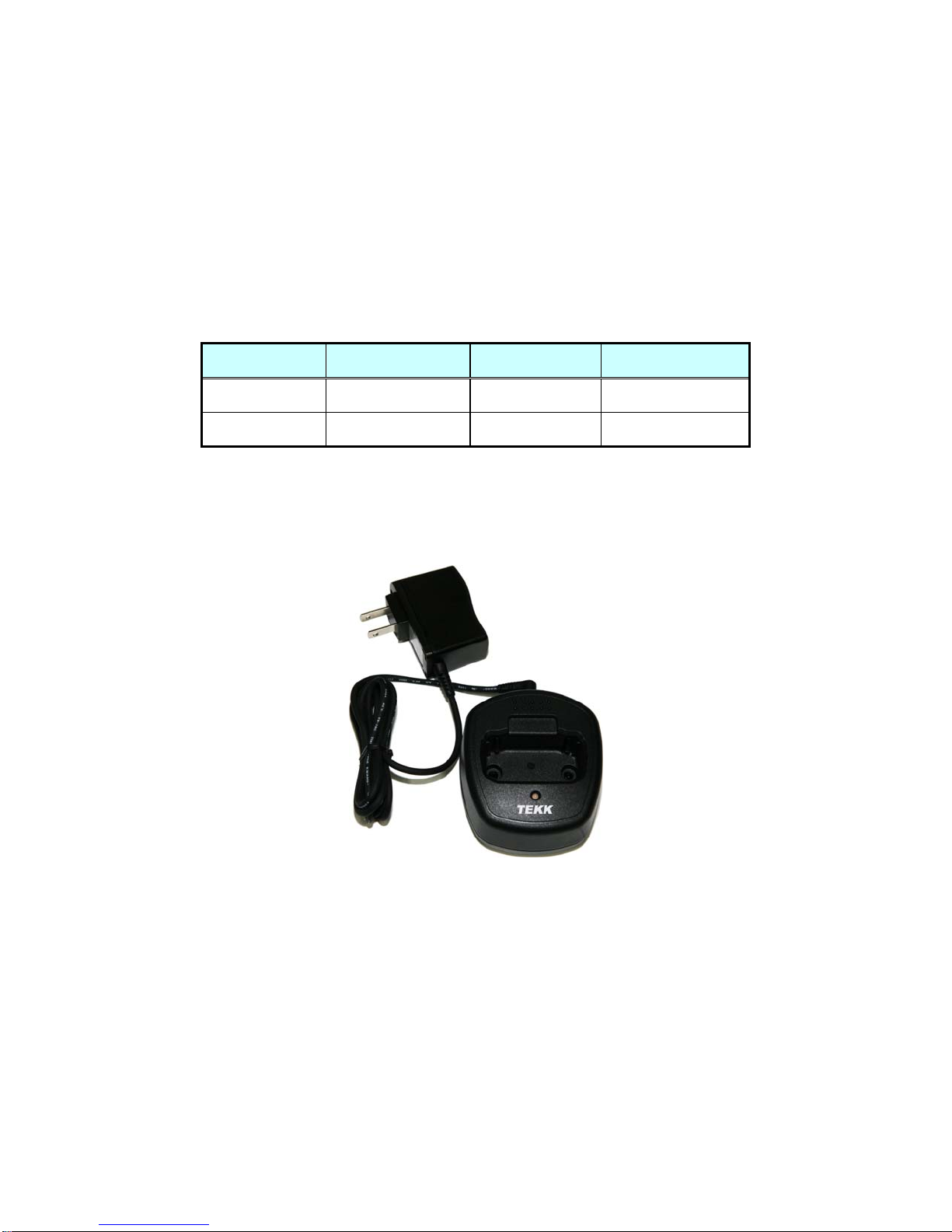
5.4 Charger (XDC-100)
The DC-1000 charger is designed to charge only the Li-ion battery enclosed in this Radio.
Figure 5-2) XDC-100 Charger
Specifications of XDC-100 Charger :
• Input Voltage : DC85 ~ 250V Battery : XSB-1800
• Quick Changing Tume : In 4Hours and half
• Operation Temperature : 0℃~+50℃
• Size : 75(W)x84.5(D)x36(H)m/m
• Charging Current : 750mA(Fast charging)

15
6. Operating Instructions of XV/XU Series Radio
6.1 Power On/Off
Turn Power switch clockwise. As soon as power is supplied, the backlight will be turned on.
If the user had set up the user ID, it will be displayed on the LCD and radio will enter into the latest
state as a signal sound is generated.
☞ Caution) When turning (power) on the radio by pressing a button on it, the radio may enter
into a special modes in which transmission and reception is impossible. Please don’t turn on
the radio by above way.
Figure 6-1) User ID
6.2 Transmission Method
For transmission, press PTT button on the left side of the radio. As soon as the user presses
keys according to the setting, DTMF or 5-tone ID will be transmitted, and during this time, voice
communication will be interrupted for several seconds. Then, red LEDs for transmission and
reception will be turned on. It is recommended to talk 5 ~ 10cm away from the microphone for the
best voice communication.
☞ Note: If the user makes transmission for more than a certain time while BCLO or TOT feature
is on, transmission will be forcefully disconnected for other users.
☞ Caution) If present channel is TX Inhibited by pc program, TX will not be worked.
(By PC Program, it could be set)
figure 6-2) When receiving figure 6-3) When transmitting
6.3 Reception Method
The user should not press PTT button during the reception. The user can adjust the volume by
Volume switch, and during reception, the green LED will be turned on. Depending on conditions of the
transmitting radio,
16
6.4 Changing Channels
Channel buttons (▼,▲) are to change channels. Press Up button (▲). Then, “beep” sound will be
generated and the channel number will be increased. Or press Down button (▼) to decrease the
channel. If the user presses Up or Down button while only one channel is set, the channel will not
be changed and a different sound from “beep” will be generated. For fast increase or decease
channel numbers, press Channel buttons (▼,▲) for a while. In this case, however, “beep” sound
will not be generated.
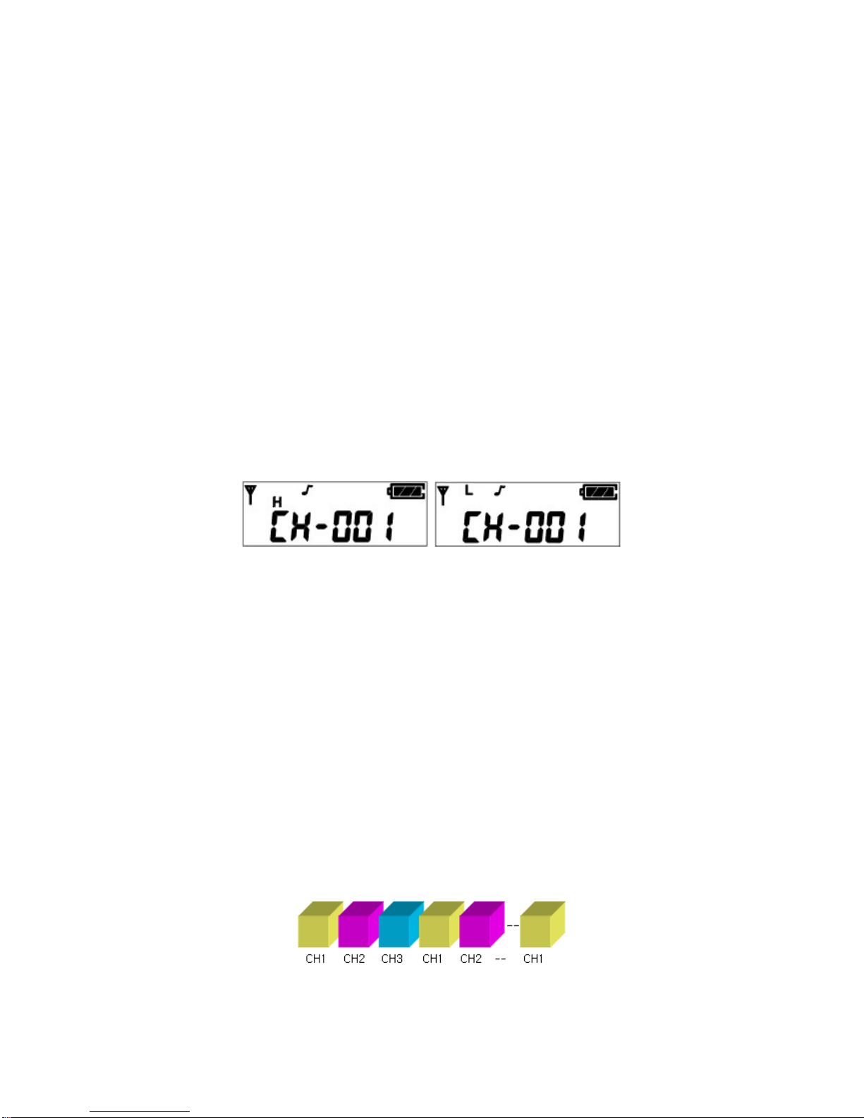
6.5 Adjusting the Transmission Power
The user can change the transmission power – High Power or Low Power. By pressing Up button
(▲) while PTT button is being pressed, the user can select “H” (High Power), or by pressing Down
button (▼), the user can select “L” (Low Power). By selecting Low power under good
communication conditions, the user can extend the battery use time.
Figure 6-4) High Power Figure 6-5) Low Power
6.6 Operation of Scan function
By pressing Menu Button (P) and Enter Button ( ) in order within 0.5 second in Standby mode,
the user can activate Scan function. After Scan function is activated, the radio will automatically
search channels and detect a channel corresponding to the frequency. To deactivate Scan
function, press Menu Button (P) once.
6.6.1 Normal Scan
At the Scan mode, the LCD displays ‘SCAN’ icon. When the scan list is S1, S2, S3, the Radio
proceeds the channel scan in the sequence of S1, S2, S3, S1, S2, …. During receiving a signal,
if you press the UP(▲) or DOWN (▼) button, you can delete the receiving channel temporarily
from the scan list and at that time, you can move to the next channel.

17
6.6.2 Priority Scan
At the Priority Scan mode, the LCD displays ‘SCAN’ and ‘P-‘ icons. The Radio scans the channel
in the sequence of P, S1, P, S2, P, S3, … at the priority scan mode. During receiving signal
through the common channel, the Radio scans the priority channel periodically and if the Radio
detects the Priority channel, it starts receiving the channel. During receiving the signal, you can
move to the following scan channel by pressing the UP or DOWN button. If you press the Enter
button, you can erase the current receiving channel temporarily from the scan list and at that time,
you can move to the next channel.
But in the course of receiving the Priority channel signal, you can not change or erase
the channel by the UP/DOWN buttons(▲,▼).
6.7 Key Lock function
During pressing the “Enter” button at the receiving standby mode, press the "▲" button within
0.5second and then, the Key Lock function will be executed and the key icon of LCD will appear. At
this situation, the other key except for the PTT and the Monitor key will not be operated. In order to
release the Lock function, press the " Enter " button and during pressing the button, press the "▼"
button within 0.5second.
6.8 2TONE / 5TONE function
6.8.1 2TONE
You can use the private and group tone functions by the central control system which is using the
2TONE SIGNALLING. If the Radio receives the tone signal, the Radio will make a Beep sound which
is advising the tone signal status and which means the Radio is ready to talk.
6.8.2 5TONE
At the tone mode, you can make the private & group calls by the 5TONE and each call memory has
the call IDs up to 30 numbers. The set-up of call memory and 5-TONE is made by PC programming. If
pressing the “Enter” button for 2seconds at the general mode, the Radio is converted to the call
mode and if pressing the "P(Program-MENU)" button for 2seconds at the call mode, the Radio is
18
converted to the general mode. By using the channel buttons (▲,▼) at the call mode, the call number
of a channel which is available for the call is displayed.
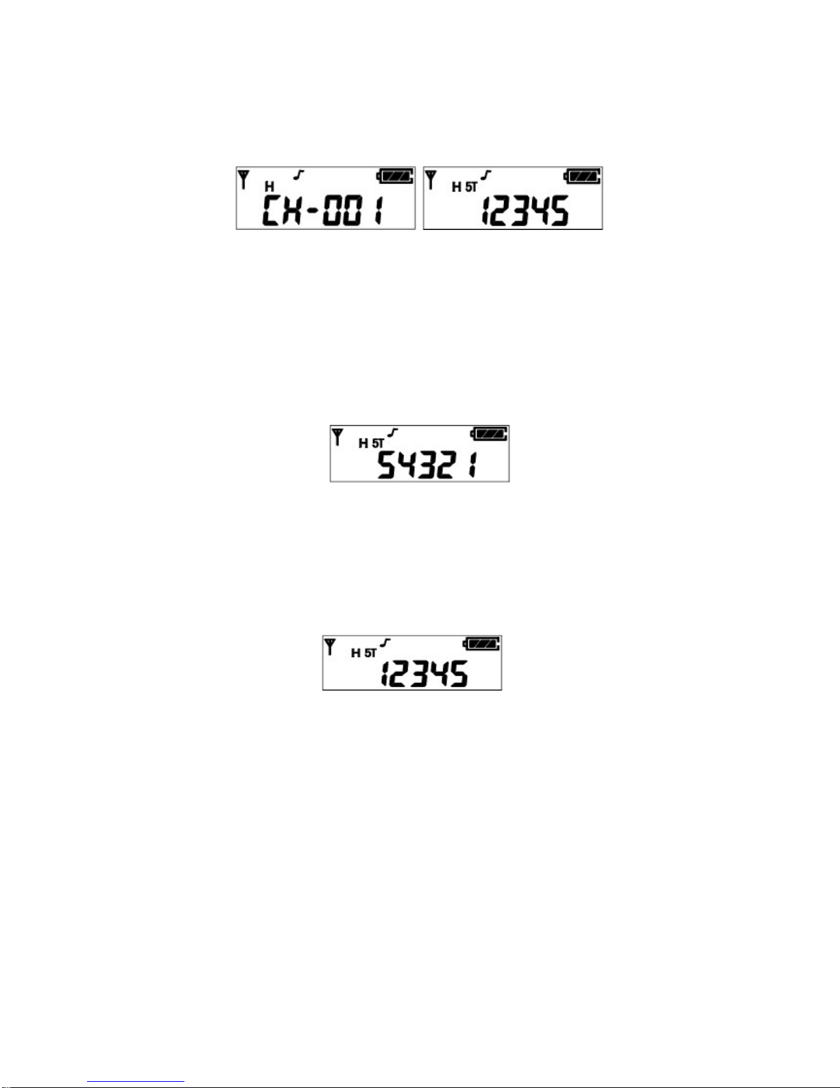
Figure 6-6) General Mode Figure 6-7) Call Mode
1) 1:1 Call at call mode
Press the “Enter” button for a long period(about 2seconds) at the general mode in order to
enter into the call mode.
① Select your party to call by using the channel button (▲, ▼). If you ( ID : 12345 ) want to call
your party(ID : 54321), select him(ID : 54321) by using the channel button
(▲,▼) at the call mode.
Figure 6-8) ID Selection
② You can call the party (ID : 54321) by pressing the “Enter” button and then, the Radio of
your party(ID:54321) displays the ID number "12345". Even though your party’s Radio is in
general mode, the Radio will be converted to the call mode automatically.
Ffigure 6-9) ID Transmission
③ After the call is completed, the Transmission and the Reception have no restriction, which
means that the TX/RX will be free.
2) 2) Group(1:N) Call at call mode
① In order to make the Group call at the call mode, the following should be set up at the PC
programming.
② If the 1st party (ID:53579) and the 2nd party(ID:52468) are in one group, the "5AAAA"which is
a call number / call name(example : baseball player) should be designated. ("A" means that all
the numbers are applied.)
19
3) If the caller makes a call to the group of baseball players, the caller’s Radio should press the
“Menu” and “▲” buttons at the same time after selecting the party with ID “1AAAA”. In this case,
the Radios of the party1 and the party2 display the ID "1AAAA". In case of the group call, the
party’s Radio displays the group ID number.
After the call is completed, the Transmission and the Reception have no restriction, which
means that the TX/RX will be free.
Figure 6-10) Group Call
3) RESET
This Reset function converts the TX/RX with no restriction to the previous Close mode. Press the
Monitor button (M) at the call mode.
①The call signal will be transmitted to the party’s Radio with the ID number + “C” tone.
② If the party’s Radio is in the Close channel and after receiving the call with the “C” tone, the
call is converted to the “TX/RX with no restriction” mode.
6.9 Emergency Call function
1) This Emergency call is used for calling the party in emergency and if pressing for about 2 seconds
the button in Red color on the top side of Radio, the Emergency Call is transmitted.
In case of setting to the emergency call channel (available by PC programming) with your ID at the
general mode or if the Radio is in the call mode, you can make an Emergency Call by pressing the
button in Red color for about 2 seconds.
The transmission is sent with the “C” tone after your ID number.
① The party’s Radio receives the “C” tone along with your ID number. The Radio recognizes it as
an emergency call and displays your ID number with the consecutive alarm sound.
2) Without transmitting the emergency call to the party, the Radio itself makes the emergency call
sound continuously.
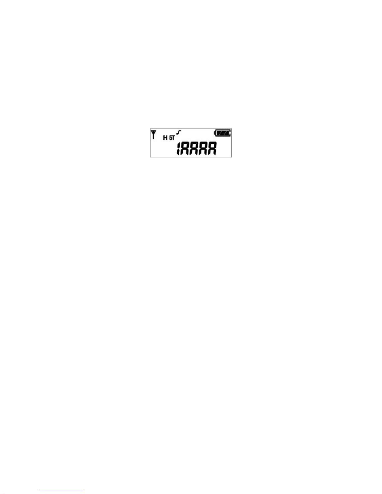
6.10 STUN function
The Radio is lost or in case you don’t want someone to use your Radio, the reception of STUN ID saved in
the Radio protects the Radio from the use by someone.

20
(The Stun ID can be set up by PC Program.) If the STUN ID is saved in the Radio, the Radio can’t be
used even after the power off & on of Radio. After receiving the UNSTUN ID, you can use the Radio.
Figure 6-11) STUN Screen
6.11 Programming function
The Programming is the function for input of the data such as Frequency/Tone/Scan
into the Radio.
* Programming Method
First, please prepare the Program cable for XP-Series Radio.
① Press the “P” button of the Radio to turn on. Then, the –Prog- message is
displayed.
② Connect the Programming cable to the Ear/Microphone Jack of Radio.
③ By using the PC Program, store the data and after disconnecting the cable, turn off the
power and turn on the power again.
Figure 6-12) Program Screen
6.12 Cloning function
The CLONING is to copy the data such as Frequency/Tone/Scan into the other Radio.
* Cloning Method
① First, please prepare the Clone cable for XP-Series Radio.
② The original Radio should be turned on with pressing the PTT button and the Radio
to be copied should be turned on with pressing the “ P “ button .
③ The original Radio displays –CLON- message, and the Radio to be copied displays
–Prog- message.
④ Connect the Clon cable to the Ear/Mic Jack of 2 Radios.
⑤ If pressing the "Enter" button of the original Radio, the copy is made and after completing,
please disconnect the cable and turn off & on the power of the 2 Radios. Finally please use the
Radio after checking if the copy is made without problem.
Other manuals for XV-100 Series
1
This manual suits for next models
3
Table of contents
Other Tekk International Two-way Radio manuals


