Tekno SCT410.3 Instruction Manual


Introduction
Additional equipment and parts needed:
2 + channel radio transmitter and receiver
1/10th scale SC (4 pole) ESC and motor
High torque steering servo
2s LiPo battery
1/10th scale SC tires, wheels & CA glue
Short Course body and paint
MOD1 Pinion (TKR4171->TKR4190)
Tools needed:
Hex drivers (1.5mm, 2.0mm, 2.5mm)
Nut drivers (5.0mm, 5.5mm, 7.0mm, 8.0mm)
Hobby knife
Needle-nose pliers
Adjustable (Crescent) wrench (for shock assembly)
4mm turnbuckle wrench
Lexan Body Scissors
Disclaimer: Tekno RC is not responsible or liable for any property or personal damage, loss, or
injury incurred as a result of using this product. This kit is meant for use by persons 14 years of
age or older and in the strict connes of a legally permitted RC track or facility.
Warnings: Always double-check that your radio gear is working properly before operating vehicle.
Never operate the vehicle indoors (unless the RC track is an indoor facility). Use caution while
operating vehicle so as not to collide with people who may be turn mashalling or who might
otherwise not be aware that a fast moving RC vehicle is in the vicinity.
Warranty: We warrant that the parts included in this kit are free from defects. If you nd a
the issue. We do not warranty parts that may be broken during operation of the vehicle or
otherwise. Refer to the end of this instruction manual for a listing of spare/replacement and
option parts. All spare parts and other info are available on our website (www.teknorc.com)
and through our network of domestic and international dealers and distributors.
Thank you for purchasing the Tekno RC SCT410 .3 1/10th Scale Electric 4WD Competition Short
Course Truck. The SCT410.3 is an improved version of the already great SCT410. We are always
working on new projects, so please check our website (www.teknorc.com) regularly for the latest
news, parts, and kits. Thanks again.
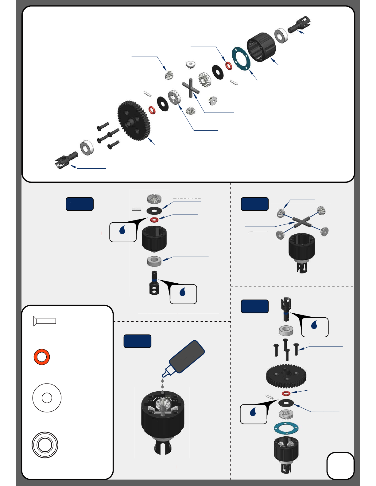
Apply grease to the groove
where the o-ring is placed
as well as the o-ring itself
Apply grease to the groove in the outdrive
Fill with 7000 wt oil to
1mm below full
DO NOT OVER FILL
TKR5145B
TKR5144
Bag A
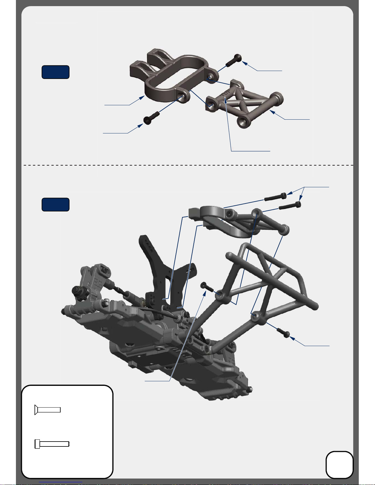
Center Differential
(overview)
TKR5237K
TKR5149X
TKR5150
TKR5150
TKR5143
TKR5113
*TKR5237
*TKR5115
(Option)
*TKR5149A
(Option)
*TKR5149A
(Option)
TKR1325
M3x14mm Flat Head Screw
x4
TKR5144
TKR5145B
Step
A-1
TKRBB08165
Ball Bearing(8x16x5mm)
x2
TKR5144
Differential 0-rings
x2
TKR5145B
Differential Shims (6x17mm)
x2
TKR1325 x4
TKRBB08165
TKR5149X
Diff
Oil
App
ly
grease to t
h
e groov
e
w
here the o-rin
g
is place
d
a
s well as the o-rin
g
itsel
f
Apply grease to the groove in the outdriv
e
Fill wi
t
h 7
000
w
t
o
il
to
1
mm
be
l
o
w f
u
l
l
D
O NOT OVER FIL
L
T
KR5145
B
T
KR51
44
*
TKR51
49A
A
(Option
)
K
R51
44
TK
K
R51
4
5B
TK
Step
A-
1
K
R132
5
x
4
TK
T
KRBB08165
T
KR51
4
9
X
X
Diff
Oil
TKR5614X
TKR5614X
TKR5150
TKR5144
3
Grease
Grease
Grease
Grease
Step
A-2
Step
A-4
Step
A-3

Apply grease to the groove
where the o-ring is placed
as well as the o-ring itself
Apply grease to the groove in the outdrive
Repeat for rear di
Fill FRONT with 7000 wt oil
Fill REAR with 5000 wt oil
to1mm below full
DO NOT OVER FILL
Repeat for rear di
Repeat for rear di
Repeat for rear di
TKR5145B
TKR5144
Bag B
Front and Rear Differential
(overview)
TKR5151
TKR5149X
TKR5150
TKR5150
TKR5143
TKR5113
TKR1325
M3x14mm Flat Head Screw
x8
TKR5144
TKR5145B
TKRBB08165
Ball Bearing(8x16x5mm)
x4
TKR5144
Differential 0-rings
x4
TKR5145B
Differential Shims (6x17mm)
x4
TKR1325 x4
TKRBB08165
TKR5149X
Diff
Oil
App
ly
grease to t
h
e groov
e
w
here the o-rin
g
is place
d
a
s well as the o-rin
g
itsel
f
Apply grease to the groove in the outdriv
e
Re
p
eat for rear di
F
i
ll
FR
O
NT wi
th
7
000
w
t
o
i
l
Fi
ll
REAR wit
h
5000 wt oi
l
to1mm below full
DO
N
O
T
O
VER FILL
Repeat
f
or rear di
Repeat
f
or rear di
Repeat
f
or rear di
T
KR5145
B
T
KR51
44
TKR51
44
TKR51
4
5B
T
KR132
5
x
4
T
KRBB08165
T
KR51
49
X
Diff
Oil
TKR5614X
TKR5614X
TKR5150
TKR5144
4
Grease
Grease
Grease
Grease
Step
B-2
Step
B-1
Step
B-4
Step
B-3
*TKR5149A
(Option)
*TKR5149A
(Option)

TKR1525
TKR5012
TKR5012
TKR5581
TKR5575X TKR5152
Front
Rear
Note: The front and rear
bulkheads are dierent.
The front has a much
greater output angle
compared to the rear.
TKR1603
TKRBB05114
TKRBB05114
TKR1226
TKR1222
TKR1222
TKR1525
TKR1222
TKR1226
TKRBB05114
TKR1525
M3x14mm Cap Head Screw
x4
TKRBB05114
Ball Bearing (5x11x4)
x2
TKR1603
M5x4mm Set Screw
x1
x2
TKR1222
13x16x0.1mm Diff shim
TKR1226
5x7x0.2mm shim
x1
TKR1603
Grease
Note: at spot
*may not be needed
*may not be needed
Note: at spot
*TKR5581C
(Option)
TKR5581
*TKR5581C
(Option)
TKRBB05114
TKR
1
52
5
F
ro
n
n
t
Rea
r
r
Note: The front and rear
bu
lkh
eads
a
r
e
d
i
e
r
e
n
t.
The front has a muc
h
g
reater output ang
l
e
compare
d
to t
h
e rear.
TKRBB05114
TKRBB0511
4
0
511
4
T
KRBB
0
T
KR1
2
2
2
6
TKR1222
1222
TKR1222
TKR
1
52
5
TKR1
6
0
3
G
r
ease
p
a
t s
p
o
t
N
ote:
a
*
d
ma
y
not
b
e nee
d
e
d
*
m
ay not be needed
p
at s
p
o
t
N
ote:
T
KR558
1
*
TKR5581
C
*
(
Option
)
Bag C
Front Gearbox
(overview)
5
Thread
Lock
Note: TKR1222 and TKR1226 Shims - The gear mesh should be tight without any binding. TKR1226 should
always be installed. Then test tment of the di with both TKR1222 shims on the gear-side of the di. If the di
turns freely without binding, continue to next step. If the di binds and does not turn freely (it will make a
grinding or crunching sound when spun), remove one TKR1222 shim from the gear side and install it onto the
other side of the di. Reassemble and test the mesh again. If it is still binding, remove the second TKR1222 shim
from the gear side and install it onto the other side of the di. When you are satised that you have the best
gear mesh possible continue to the next step. You may end up using only one shim on the gear side.
Step
C-1
Step
C-2
Step
C-3

TKR5575X
TKR5016B
TKR5152
TKR5016B
TKR5584
TKR1222
TKR1222
TKR1525
TKR1222
TKR1525
M3x14mm Cap Head Screw
x4
TKRBB05134
Ball Bearing (5x13x4)
x2
TKR1603
M5x4mm Set Screw
x1
TKR1222
13x16x0.1mm Diff Shim
x2
TKR1226
5x7x0.2mm Shim
x1
TKR1603
TKRBB05134
TKRBB05134
TKRBB05134
TKR1226
TKRBB05134
TKR1603
TKR1525TKR1525
Grease
Front
Rear
Note: at spot
Note: at spot
*TKR5584C
(Option)
TKR5584
*TKR5584C
(Option)
Note: The front and rear
bulkheads are dierent.
The front has a much
greater output angle
compared to the rear.
TKR1226
TK
R1
22
2
TKR1222
KR1222
T
KR1525
TKR1
6
0
3
T
KRBB051
3
34
0
513
4
TKR
BB0
TKR12
2
26
TKR
15
2
5
TKR1525
G
r
ease
Fro
n
nt
R
ea
r
r
p
a
t s
p
o
t
Note:
a
at spot
Note:
T
KR558
4
*TKR558
4
C
(
Option)
Note:
Th
e
f
r
o
n
t
a
n
d
r
ear
bu
lkh
eads
a
r
e
d
i
e
r
e
n
t.
T
he front has a muc
h
greater output ang
le
c
om
p
ared to the rear.
Bag D
Rear Gearbox
(overview)
6
Thread
Lock
Note: TKR1222 and TKR1226 Shims - The gear mesh should be tight without any binding. TKR1226 should
always be installed. Then test tment of the di with both TKR1222 shims on the gear-side of the di. If the di
turns freely without binding, continue to next step. If the di binds and does not turn freely (it will make a
grinding or crunching sound when spun), remove one TKR1222 shim from the gear side and install it onto the
other side of the di. Reassemble and test the mesh again. If it is still binding, remove the second TKR1222 shim
from the gear side and install it onto the other side of the di. When you are satised that you have the best
gear mesh possible continue to the next step. You may end up using only one shim on the gear side.
*may not be needed
*may not be needed
Step
D-1
Step
D-2
Step
D-3
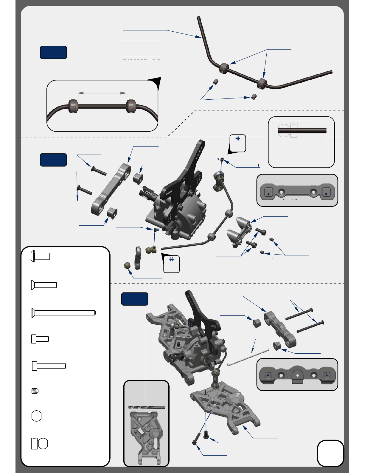
Stock Position
(”D” Block)
Stock Position
(”C” Block)
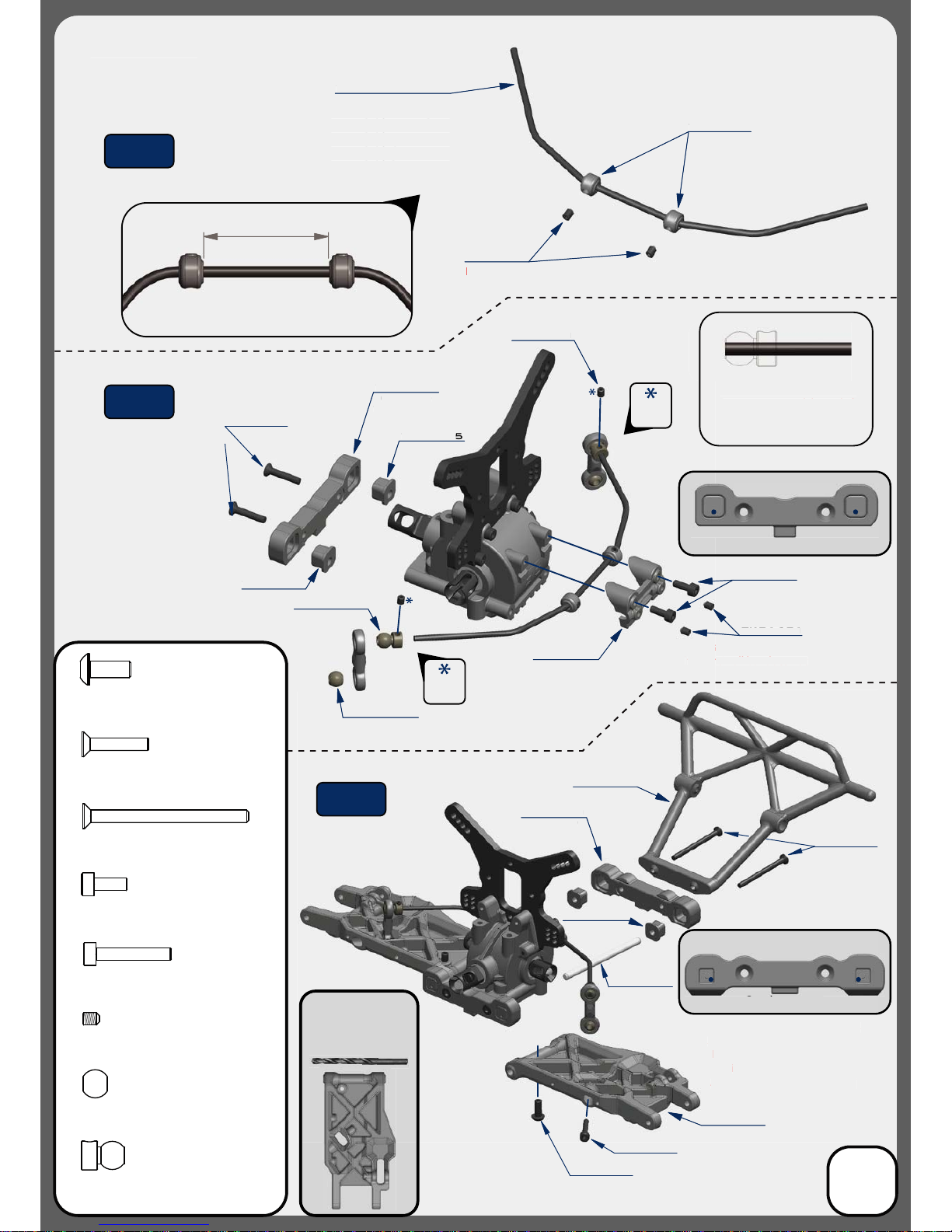
30.2
TKR1601
TKR1601
TKR1601
TKR5086
TKR5491 - 2.4mm
TKR5086
Install the Sway Bar Ball onto the
Sway Bar Wire until the end of
the wire is ush with the ball as
picture above.
Note: Loosen the M3x4 set screw (TKR1601)
if
the anti-roll bar does not
turn freely.
Note: With these stock settings,
Anti-Squat is: 3° / Rear Toe is: 2°
For reference: With center dot
inserts in both braces,
Anti-Squat = 3° / Rear Toe = 3°
Note: Do not over-tighten
TKR5049A
TKR5165
TKR5730
TKR5165
TKR5730
TKR5799
TKR5515
TKR5079A
TKR5165 TKR1522
TKR1522
M3x8mm Cap Head Screw
Bag E
Rear End
*TKR5490 - 2.3mm
*TKR5492 - 2.5mm
*TKR5493 - 2.6mm
*TKR5494 - 2.8mm
*TKR5495 - 3.0mm
(Option)
(Option)
*TKR5163
(Option)
*TKR5164
30
.
2
T
TKR1601
TKR1601
TKR1
6
0
1
TKR5086
TKR5
4
91 - 2.
4
m
m
T
KR
5
08
6
I
nsta
ll
t
h
e Sway Bar Ba
ll
onto t
he
S
wa
y
Bar Wire until the end of
t
h
e
wir
e
i
s
us
h wi
t
h
t
h
e
ba
ll
as
p
icture a
b
ove
.
s
en t
h
e M3x4 set screw
(
TKR1601
)
N
ote: Loo
s
i
f
nt
i-r
o
ll
ba
r
does
n
ot
t
h
e
an
t
urn
f
reel
y
.
Note: With these stock settings,
Anti-Squat is: 3° / Rear Toe is: 2°
Fo
r r
efe
r
e
n
ce:
Wi
t
h
ce
n
te
r
dot
inserts in both braces
,
Anti-Squat = 3° / Rear Toe = 3°
N
N
ote: Do not over-tig
h
ten
TKR50
49
A
T
KR
5
1
65
TKR5730
TK
R5
16
5
T
KR5
7
30
TKR5799
T
KR55
1
5
TKR5079A
TKR516
5
TKR
15
22
Bag E
Rear End
*TKR5
49
0 - 2.3mm
*TKR54
9
2 - 2.5mm
*TKR5493 - 2.
6
mm
*TKR5
494
- 2.8mm
*TKR54
9
5 - 3.0mm
(
Option
)
(
Option
)
*TKR
5
1
63
(
Option
)
*
TKR
5
1
6
4
Thread
Lock
Thread
Lock
7
TKR1327
TKR1333
M3x40mm Flat Head Screw
x2
TKR1238
M4x10mm Droop Screw
x2
TKR5049A
Pivot Ball Sway Bar
x2
x6
TKR5079A
Stabilizer Ball
x2
TKR1528
M3x18mm Cap Head Screw
x2
x2
TKR1327
M3x16mm Flat Head Screw
x2
TKR1333TKR1333
TKR1238
TKR1528
S
toc
k
Positi
on
S k
(
”D” B
l
oc
k)
Stock
P
os
i
t
i
o
n
(”C” Block)
(”C”
Block
)
TKR1601
M3x4mm Set Screw
Step
E-1
Step
E-2
Step
E-3
TKR5020
Use a #19 drill bit or
4mm reamer to ream
arms until hinge pin
falls through freely.
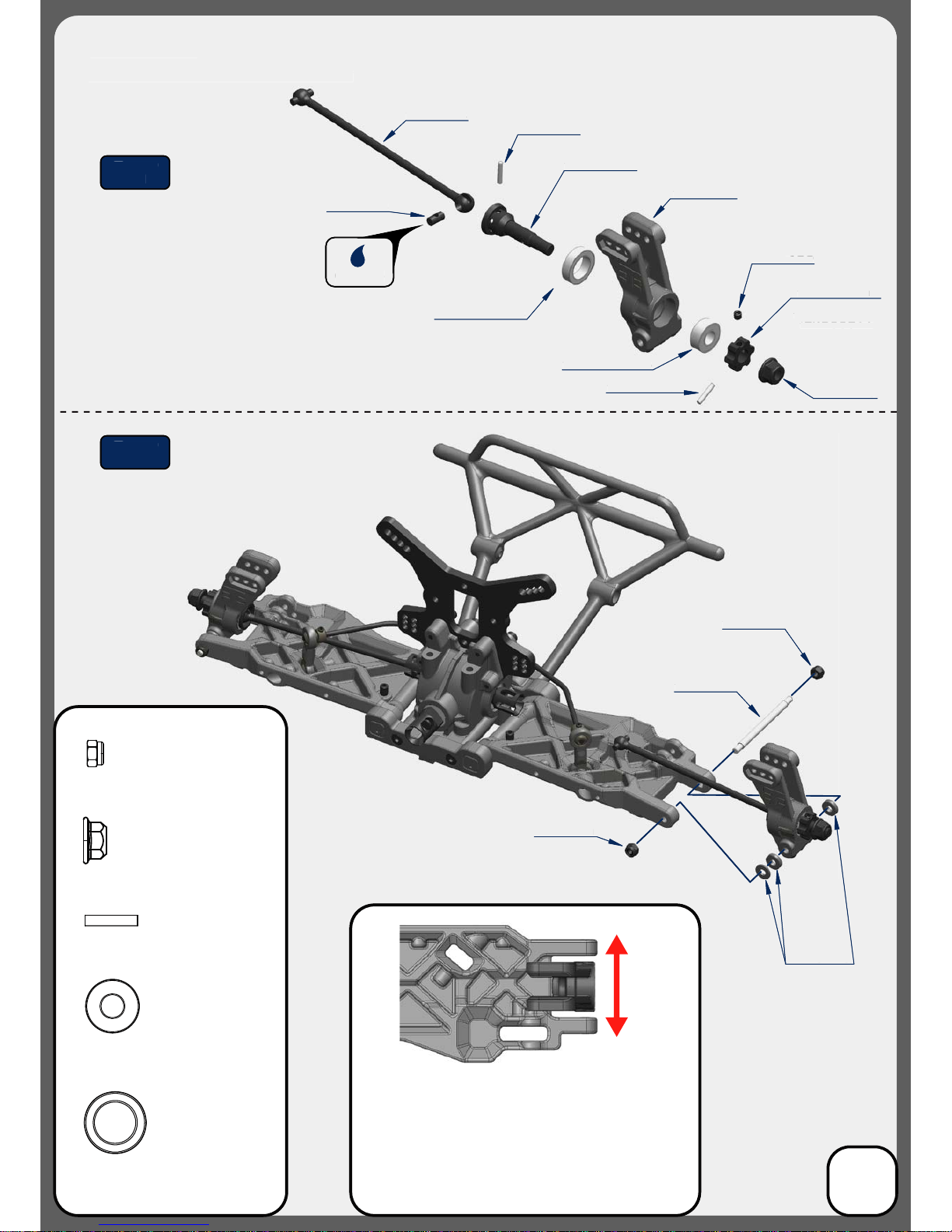
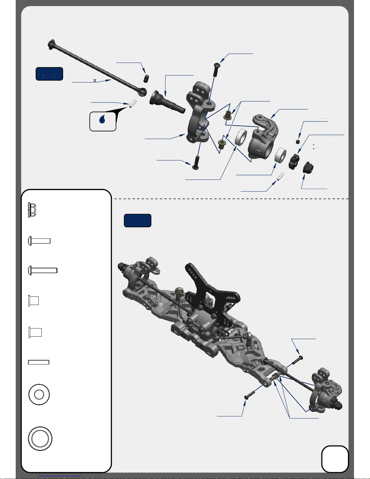
TKR5572
TKR6856
TKR5570B
TKR5545
TKRBB10154
TKRBB06135
TKR6856
TKR5571M
TKR5534
TKR5165
TKR1201
TKR1201
Changes to the wheelbase have a dramatic eect on handling,
since it shifts the disribution of weight over the rear wheels.
This adjusts traction. By shortening the wheelbase at the rear, you
are placing more weight over the rear wheels.
Changes to the wheelbase also change the amount of sweep the
rear driveshaft will have. More driveshaft sweep creates an eect
similar to anti-squat, where the rear end gets pushed upwards on
throttle. This helps reduce chassis slap landing jumps on throttle.
TKR1609
TKR6856 TKR1215
TKR6856
CV Joint Pin
x4
TKR1201
M3 Locknut Black
x4
TKRBB10154
Ball Bearing (10x15x4)
x2
TKRBB06135
Ball Bearing (6x13x5)
x2
*TKR5571
*TKR5571-17
*TKR5571A
*TKR1654X
(Option)
Grease
TKR1215
M4 Lock Nut Flange Black
x2
(FRONT)
(REAR)
Step
F-1
Step
F-2
Bag F
Rear Hub/CVA Assembly
TKR5572
T
KR685
6
TKR5570B
T
KR5545
T
KRBB1015
4
T
KRBB0
6
13
5
TKR
6
8
56
T
KR55
71M
T
KR
55
34
T
KR
5
1
65
T
KR
1
20
1
TKR
1
20
1
60
9
TK
R1
TKR
6
8
56
TKR121
5
*TKR557
1
*
TKR5571-1
7
*TKR55
71A
*TKR16
5
4X
(
Option
)
G
r
ease
Step
F-
1
S
te
p
F
-
2
Bag F
Rear Hub
/
CVA Assembl
y
8
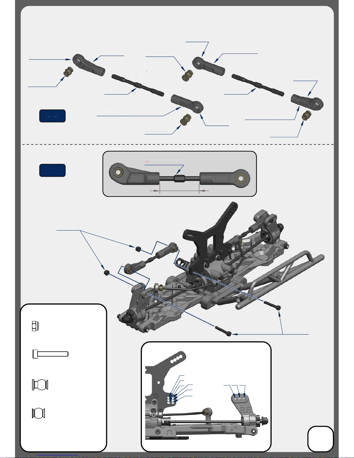
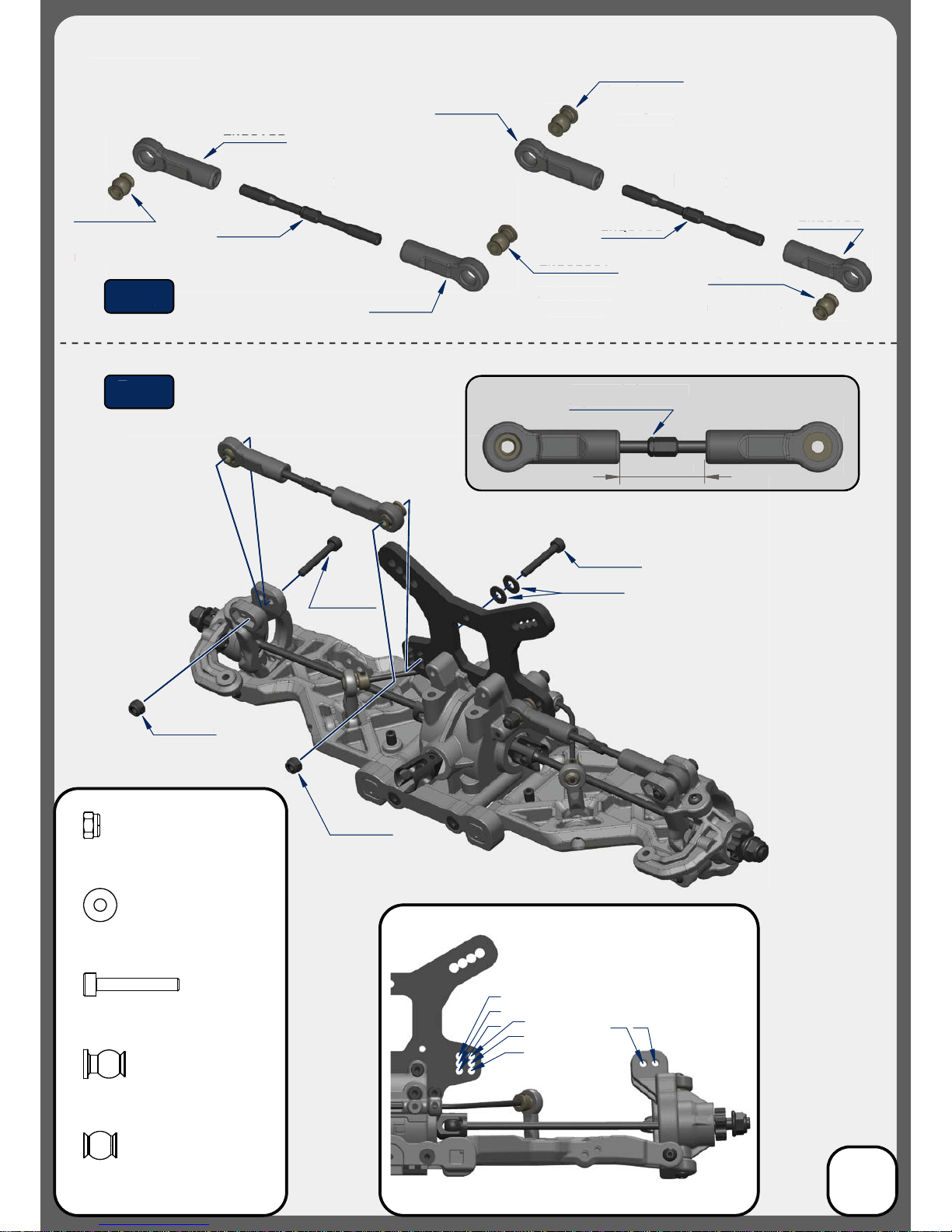
TKR5188
TKR5123
TKR5188
TKR5052A
This side mounts on hub
Note: angled link
This side mounts on shock tower
Note: straight link
TKR5053A
25.50
Note: Notch always goes
on
left side of vehicle
1
2
34
5
6
A
B
C
Stock position is 6/B
TKR1529
TKR1201
Right
TKR5053A
This side mounts on hub
Note: angled link
This side mounts on shock tower
Note: straight link
TKR5188
Left
TKR5123
TKR1201
M3 Locknut Black
x4
TKR1529
M3x20mm Cap Head Screw
x4
TKR5053A
Pivot Ball M3x6.8mm
No Flange
x2
TKR5052A
Pivot Ball M3x6.8mm
x2
TKR5188
TKR5052A
Step
F-3
Step
F-4
Bag F
Rear Camber Links
TKR
51
8
8
T
KR5123
TKR5188
TKR5052A
T
hi
s
s
i
de
m
ou
n
ts
o
n h
ub
Note: an
g
led lin
k
This side mounts on
s on shock tower
Note: straig
h
t
l
in
k
TKR
5
0
5
3
A
25
.
50
25 50
N
ote: Notch always goes
on
on
left side of vehicle
lef
t s
ide
of
ve
hic
le
T
KR152
9
TKR1201
Right
Righ
T
KR
5
0
5
3A
This side moun
mounts on hub
N
ote: an
g
led link
Th
is si
d
e mounts on s
h
oc
k
towe
r
Note: strai
g
ht link
T
KR5188
Left
Left
T
KR
51
23
T
KR
51
8
8
TKR
5
0
5
2
A
Step
F
-
3
Step
F
-
4
Bag F
Rear Camber Link
s
9
TKR1528
M3x18mm Cap Head Screw
x2
TKR1327
M3x16mm Flat Head Screw
x4
Note: “Top” side up
Step
F-5
Step
F-6
Bag F
Rear Bumper
N
ote: “To
p
” side u
p
S
tep
F
-
5
Step
F
-
6
Bag F
Rear Bumper
10
TKR1327
TKR1327
TKR1327
TKR5799
TKR1327
TKR5799
TKR1528
Stock Position
(”B” Block)
Stock Position
(”A” Block)
30.2
TKR1601
TKR1601
TKR1601
TKR5086
TKR5084 - 2.6mm
TKR5086
Install the Sway Bar Ball onto the
Sway Bar Wire until the end of
the wire is ush with the ball as
picture above.
Loosen the M3x4 set screw
(TKR1601) if
the anti-roll bar
does not
turn freely.
Note: Do not over-tighten
TKR1601
TKR1522
TKR1522
M3x8mm Cap Head Screw
Bag G
Front End
*TKR5080 - 2.2mm
*TKR5081 - 2.3mm
*TKR5082 - 2.4mm
*TKR5083 - 2.5mm
*TKR5085 - 2.8mm
*TKR5087 - 3.0mm
(Option)
Stock
Pos
i
t
i
o
n
SkP
(
”B” Block
)
Stock
P
os
i
t
i
o
n
(”
A” B
l
oc
k
)
30.2
TKR1
6
0
1
T
KR1
6
01
TKR160
1
508
6
TK
R
TKR
5
084 - 2.
6m
m
m
TKR5086
I
nsta
ll
t
h
e Swa
y
Bar Ba
ll
onto t
he
S
way Bar Wire until the end o
f
t
h
e
wir
e
i
s
us
h wi
t
h
t
h
e
ba
ll
as
p
icture above
.
oose
n
t
h
e
M
3
x4
set
sc
r
ew
L
T
KR1601) if
(T
the
a
n
t
i-r
oll
bar
does
n
ot
turn freely
.
Note: Do not over-ti
g
hten
T
KR1
6
01
T
KR
15
2
2
Bag G
Front End
*TKR5080 - 2.2
m
mm
*TKR5081 - 2.3
m
mm
*TKR
5
082 - 2.4
m
mm
*TKR5083 - 2.5
m
mm
*TKR5085
-
2
.
8m
mm
*TKR508
7
- 3.0
m
mm
(
Option)
Thread
Lock
Thread
Lock
11
TKR1327
TKR1333
M3x40mm Flat Head Screw
x2
TKR1238
M4x10mm Droop Screw
x2
TKR5049A
Pivot Ball Sway Bar
x2
x6
TKR5079A
Stabilizer Ball
x2
TKR1528
M3x18mm Cap Head Screw
x2
x2
TKR1327
M3x16mm Flat Head Screw
x2
TKR1333
TKR1528
TKR1238
TKR5020
TKR1601
M3x4mm Set Screw
Step
G-1
Step
G-2
Step
G-3
TKR5730
TKR5730
(Option)
*TKR5162
(Option)
*TKR5161
TKR5516
TKR5165
TKR5049A
TKR5165
TKR5165
TKR5165
Note: With these stock settings,
Kick Up is: 11° / Arm Sweep is: 0°
For reference: With center dot
inserts in both braces,
Kick Up = 10° / Arm Sweep = 0°
Use a #19 drill bit or
4mm reamer to ream
arms until hinge pin
falls through freely.
TKR5572
TKR5541B
TKR5554A
TKR1404
TKRBB06135
TKR5542
TKR5570B
TKR1407
TKR1407
TKR5555A
TKRBB10154
TKR1404
TKR1215
TKR6856
CV Joint Pin
x4
TKR5554A
Spindle Pin Sleeve
x4
TKR5555A
Suspension Pin Sleeve
x4
Grease
TKR6856
TKR6856
TKR1215
M4 Lock Nut Flange Black
x2
TKRBB10154
Ball Bearing (10x15x4)
x2
TKRBB06135
Ball Bearing (6x13x5)
x2
TKR1404
M3x12mm Button Head Screw
x4
TKR1407
M3x16mm Button Head Screw
x4
Step
H-1
Step
H-2
TKR5571M
*TKR5571
*TKR5571-17
*TKR5571A
*TKR1654X
(Option)
TKR6856
TKR1609
TKR557
2
TKR55
4
1B
TK
R5
55
4A
TKR140
4
T
KRBB0
6
13
5
TK
R5
54
2
TK
R5
57
0B
TKR1
4
0
7
T
KR140
7
TKR
5555A
TKRBB101
54
T
KR1
4
0
4
T
KR
1
2
15
Greas
e
T
KR685
6
T
KR685
6
Step
H
-
1
Ste
p
H
-
2
T
KR55
7
1M
T
*TKR557
1
T
KR55
7
1-1
7
*T
*
TKR557
1A
*
*
TKR16
5
4X
*
(
Option
)
TKR
6
85
6
1
6
0
9
TKR
Bag H
Front Spindle / CVA Assembly
12
TKR1529
Stock position is 2/A
TKR1221
TKR1201
TKR1201
TKR1529
20.50
TKR1201
M3 Lock Nut Black
x4
TKR1529
M3x20mm Cap Head Screw
x4
TKR5052A
Pivot Ball M3x6.8mm
x2
TKR5053A
Pivot Ball M3x6.8mm
No Flange
x2
TKR5188
TKR5123
TKR5188
TKR5052A
TKR5053A
Right
TKR5188
This side
mounts on hub
Note: no ange
This side
mounts on hub
Note: no ange
This side mounts
on shock tower
Note: ange
This side mounts
on shock tower
Note: ange
TKR5188
Left
TKR5123
TKR5053A
TKR5052A
TKR1221
M3x8mm Washer
x4
Note: Notch always goes
on
left side of vehicle
1
2
34
5
6
A
B
Step
H-4
Step
H-3
Bag H
Front Camber Links
TKR152
9
TKR1221
T
KR
1
20
1
TKR120
1
TKR
1
52
9
TKR5188
TKR5188
TKR512
3
TKR
5
18
8
TKR
5
0
5
2
A
TKR5
5053A
R
ig
ht
R5188
TKR5
This sid
side
mounts on hub
ub
N
ote: no ange
Th
i
s
s
si
de
mou
n
t
ts
o
n
hub
N
ote:
n
n
o
an
ge
T
hi
s
s
i
de
m
ou
n
ts
on s
h
oc
k
towe
r
Note: ange
Note
T
hi
s
s
i
de
m
ou
n
ts
on shock towe
r
N
ote:
an
ge
TKR5188
L
ef
t
TKR5
R5123
TKR
K
R5
05
3A
T
KR
5
0
5
2A
20
.
50
N
ote: Notch alwa
y
s goes
o
n
le
f
t side o
f
vehicl
e
S
te
p
H
-
4
S
te
p
H
-
3
Bag H
Front Camber Links
13
TKR1323
TKRBB050825
TKRBB050825
Note: Apply
a small drop
of oil for
easy o-ring
installation.
Note: Tighten nut all the way down,
then back it o 3 full turns
Stock Position
(in MIDDLE hole)
*Note orientation of Ackermann
plate when installing
TKR1201
TKRBB06103
TKRBB06103
TKR1529
Note: Stock bumpsteer setting is
4 washers
under the steering ball link.
4 x TKR1221
TKR1221
TKR5122
TKR5103
28.50
TKR1323
M3x10mm Flat Head Screw
x2
TKR1201
M3 Lock Nut Black
x2
O-ring 16x12x2
TKR5231
x1
TKRBB06103
Ball Bearing (6x10x3)
x4
TKRBB050825
Ball Bearing (5x8x2.5)
x4
TKR1529
M3x20mm Cap Head Screw
x2
TKR5052A
Pivot Ball M3x6.8mm
x4
TKR1221
M3x8mm Washer
x8
TKR5052A
TKR5052A
TKR5052A
Thread
Lock
Thread
Lock
Thread
Lock
Right
Left
Step
I-1
Step
I-2
Step
I-3
Step
I-4
TKR5117
TKR5056
TKR5123
TKR5052A
TKR5104
TKR5104
TKR5101X
TKR5231
TKRBB06103
TKRBB050825
TKR5104
TKR1529
TKR5103
TKR1201
TKRBB06103
TKR5052A
*TKR5100
(Option)
TKR1323
5
T
KRBB05082
5
TKRBB050825
Note: Appl
y
a sma
ll
d
ro
p
of
o
il
fo
r
e
asy o-ring
insta
ll
ation
.
Note: Tig
h
ten nut a
ll
t
h
e wa
y
d
own,
t
h
e
n
bac
k i
t
o
3
f
u
ll
tu
rn
s
TKR
1
20
1
TKRBB0
6
10
3
TKRBB06103
TKR1529
TKR1529
T
KR
1
22
1
TKR5122
TKR
5
10
3
TKR5052A
TKR505
2A
TKR5052A
T
h
rea
d
L
oc
k
Thr
ead
L
oc
k
Thr
ead
Loc
k
R
i
ght
Lef
t
Step
I
-
1
Step
I
-
2
S
te
p
I
-
3
Step
I-
4
Bag I
Steering Assembly
(overview)
14
28 50
28
.
50
Note: Stock bumpsteer settin
g
is
4
w
as
h
e
r
s
under the steerin
g
ball link.
4 x TKR122
1
S
toc
k
Position
(in
MIDDLE
hole)
(in MIDDLE hole)
*N
ote
o
ri
e
n
tat
i
o
n
of
A
c
k
e
rm
a
n
n
pl
ate w
h
en insta
ll
in
g
Note: Notch always goes
on
left side of vehicle

TKR1201
TKR1443
TKR5102A
TKR1443
Note: on steps
J-1, J-2 and J-4
Do not tighten
the chassis
screws
all the way down
until the assembly
steps are complete.
Position the entire
front assembly on
the chassis and
tighten each
screw evenly.
TKR1528 TKR1443
TKR1344
TKR1343
TKR5062
Note: Initial bumpsteer setting
is 2 washers
above and 2 washer below the steering ball link.
TKR1327
TKR1344
TKR5107
TKR5518B
TKR1529
TKR1528
M3x18mm Cap Head Screw
x2
TKR1522
M3x8mm Cap Head Screw
x1
TKR1343
M4x10mm Flat Head Screw
x2
TKR1344
M4x12mm Flat Head Screw
x6
TKR1201
M3 Lock Nut Black
x2
TKR1327
M3x16mm Flat Head Screw
x2
TKR1443
M4x10mm Button Head Screw
x5
TKR1529
M3x20mm Cap Head Screw
x2
TKR1221
M3x8mm Washer
x8
Note Step J-2:
Line up the bottom of the
steering posts (TKR5102)
with the corresponding recess
cut in the
chassis
.
Thread
Lock
Thread
Lock
Step
J-2
Step
J-4
Step
J-3
Step
J-1
TKR1522
TKR1201
TKR1201
TKR1443
TK
R1
44
3
T
KR5102
A
T
KR1443
N
ote: on step
s
J-1, J-2 and J-
4
Do not tighten
th
e c
h
assis
scre
w
s
a
ll the wa
y
down
until the assembl
y
s
te
p
s are com
pl
ete.
P
osition t
h
e entir
e
f
ront assembl
y
on
t
h
e
c
h
ass
i
s
a
n
d
t
ig
h
ten eac
h
s
crew even
ly
.
T
KR1528 TKR144
3
TKR1344
TKR1344
TKR13
43
TKR5062
N
ote: Initial bumpsteer settin
g
i
s
2
w
was
h
e
r
s
a
bove and 2 washer below the steeri
n
n
g ball link
.
TK
R1
32
7
T
KR134
4
TKR5
1
0
7
T
KR551
8B
TKR152
9
N
ote
S
tep J-2:
Line u
p
the bottom of th
e
steering posts (TKR5102)
w
it
h
t
h
e correspon
d
in
g
recess
cut
in
t
h
e
ch
assis
.
T
h
rea
d
L
oc
k
Th
r
ead
L
oc
k
S
tep
J
-
2
Step
J-4
S
tep
J
-
3
Step
J-
1
TKR
15
22
Bag J
Front End Assembly
15

TKR5107
TKR5263
TKR1522
TKR5579
TKR1443
TKR5062
TKR1344
TKR1343 x5
TKR1443
TKR5062
TKR5576
TKR1344 x5
TKR1524
TKR1522
M3x8mm Cap Head Screw
x2
TKR1524
M3x12mm Cap Head Screw
x4
TKR1343
M4x10mm Flat Head Screw
x5
TKR1443
M4x10mm Button Head Screw
x2
TKR1344
M4x12mm Flat Head Screw
x7
Thread
Lock
Thread
Lock
Step
K-1
Step
K-3
Step
K-2
Step
K-4
TKR5263
*TKR5262
(option)
TKR5260
T
KR5
1
0
7
7
TKR52
63
TKR1522
T
KR5579
T
KR1
44
3
TKR
5
0
6
2
TKR13
44
TKR1343 x
5
T
KR1
44
3
TKR
5
0
62
TKR55
7
6
TKR1344 x
5
TKR1
5
2
4
T
hr
ead
Lock
T
h
rea
d
L
oc
k
S
te
p
K
-
1
S
te
p
K
-
3
Step
K
-2
S
te
p
K-
4
T
KR5263
*
TKR5262
(
option
)
TKR52
6
0
Bag K
Center/Rear
Assembly
16

17
Shock Filling Instructions
For both front and rear shocks
Standard or Vented Cap Build:
Step 1: Extend the shock shaft all the way down. Fill the shock with oil until the it is about 90% full.
Step 2: Slowly pump the shock shaft up and down 3-5 times to release air bubbles from underneath
the piston.
Step 3: Let the shock rest vertically with the shock shaft fully extended for ve minutes or until all
the air bubbles have released.
Step 4: Next you will top o the shock with oil, to about 1-2mm below the top edge.
(If you do overll the shock, it won’t hurt performance, it will just spill out and make a little bit of a
mess. If you underll the shock, it will cause air to be trapped inside.)
Step 5: Place the bladder INSIDE the shock cap and put a few drops of oil on the bladder.
Step 6: Put a paper towel down below the build to catch drips and have another ready to
wipe o excess oil. Place the cap on the shock and screw down about half way. Lay the shock
over about 45 degrees with the bleeder hole facing up.
Step 6A: (Standard non-vented) Push the shaft in for the amount of rebound desired.
Step 6B: (Vented “Stock”) Push the shaft in until about 15mm of shaft is showing.
tMake sure that you match the rebound amount between the left and right shocks.
tOil should be oozing out of the bleeder hole.
Step 7: Hold the cap rmly in place with the bleeder hole facing up and turn the shock body until
hand tight. The shock will continue to ooze oil.
Step 8: Fully tighten down each shock with shock tools until cap is secure and wipe excess oil away.
Emulsion Build:
Prep your shock caps TKR6018 (optional for EB48) accordingly by drilling out the large angled
bleeder hole in the top of the cap. Place the larger thin o-ring around the base of the threads
where the shock cap screws on (see diagram on the next page). This seal is crucial to the build.
Follow steps 1-4 above.
Step 5: Rebound is more of a natural side eect of an emulsion shock. It’s not something that can
be set accurately because you run the risk of hydrolocking the shock if you do not push the shaft
all the way in when you bleed it. For now leave the shaft fully extended.
Step 6: Fill the shock up, over lling just slightly without spilling to create a small dome of oil.
Step 7: Place a little bit of oil in the shock cap and quickly put the shock cap on the shock body.
Tighten the cap all the way down. Very slowly push the shaft in. Oil will start to bleed out of the top
of the cap. While wiping away excess oil, continue to slowly push the shaft in ALL THE WAY.
If no oil comes out when the shaft is fully inserted, you will need to start over at step 6.
Step 8: Install the TKR1341 M4x6mm at head screw and TKR5125 black o-ring to seal
the cap (see diagram). Tighten until o-ring is fully seated.
The following steps and information will provide you with the best way to ll and bleed your
shocks. After thorough testing, we've found it's easiest to complete steps 1 through 3 on each
shock before moving onto step 4. By the time you've nished step 3 on the last shock the rst
one will be ready for step 4.

TKR6036
TKR6140
TKR1211
TKR1528
TKR6007 TKR5527
TKR1212
Note: slot in spring
perch should face
outside of vehicle.
Note: Tighten TKR1211 lock nut all the way down, then back o 1/4 turn. Use thread lock!
TKR1523
TKR5791
TKR1605
TKR6008
TKR6008 TKR6009
TKR6002
M2.5 Lock Nut Zinc
TKR1200
x2
TKR1528
M3x18mm Cap Head Screw
x2
TKR1212
M4 Lock Nut Flange
x2
TKR1211
M3 Lock Nut Flange Black
x2
*TKR6046
*TKR6047
*TKR6048
*TKR6035
*TKR6037
*TKR6038
*TKR6039
(Option)
TKR1200
TKR6008
TKR6004
TKR6140
TKR5049A
TKR1341
*TKR6004T
(Option)
*TKR6050
*TKR6051
*TKR6052
*TKR6053
*TKR6054
*TKR6063
*TKR6064
*TKR6065
(Option)
Note:
shaft guide
orientation
Note:
front shocks use
shorter shock bodies -
TKR6002,
shorter shock shafts -
TKR6004,
shorter springs -
TKR6036
and shorter shock boots -
TKR6143
Note: Use green
slime or oil on
shock shaft
threads AND
O-rings to
prevent tearing
and leaking.
TKR6143
TKR6018
TKR6009
Vented build requires a
1-2mm hole drilled in
addition to the bleeder hole
Drill 1-2mm
hole here
for emulsion
Drill 1-2mm
hole here
for bleeder
*Do not drill
bleeder
hole for this
build
**Bladder not
used in this
build
*TKR6013
(Option)
TKR6018
*TKR6003
*TKR6003B
(Option)
*TKR6015
(Option)
TKR5125
Step
L-1
Step
L-2
Step
L-3
Note: Shock boots
must be installed
before attaching
rod end.
Thread
Lock
Bag L
Front Shock Assembly
6
036TK
R6
TKR6140
TKR6
TKR1211
T
KR
1
1
52
8
TKR
6
00
7
TKR5527
T
KR
1
2
12
Note: s
l
o
t
t
in spring
perch sh
o
o
uld fac
e
outs
i
de
o
of
v
e
hi
c
l
e.
Note: Tighten TKR1211 lock nut all the wa
y
down, then back o 1/4 turn. Use thread lock
!
TKR
15
2
3
T
KR57
91
TKR160
5
TKR6008
TKR6008
TKR
6
00
9
TKR6002
6
04
6
*TK
R6
6
047*TK
R6
6
04
8
*TK
R6
6
03
5
*TK
R6
6
03
7
*TK
R6
6038
*TK
R6
6
039*TK
R6
ion
)
(
Op
t
TKR1200
TKR6008
TKR600
4
TKR
6
1
40
T
KR5049A
T
KR13
4
1
*
TKR600
4
T
(
Option
)
*TKR60
5
0
*TKR
6
05
1
*TKR60
5
2
*TKR
6
05
3
*TKR60
54
*TKR
6
0
63
*TKR606
4
*TKR
6
0
65
(
Option
)
N
ote
:
s
ha
f
t
g
uide
o
ri
e
n
tat
i
on
Note:
f
ront shocks use
s
h
orter s
h
oc
k
b
o
d
ies -
T
KR6002
,
shorter shock shafts -
T
K
R
6004
,
sh
orter sprin
g
s -
TKR
6036
and shorter shock boots -
TK
R
6143
N
ote:
U
se green
sl
im
e
o
r
o
i
l
o
n
s
h
oc
k
s
h
aft
threads AN
D
O-rings to
prevent tear
i
n
g
a
nd leakin
g.
TKR
6
1
43
T
KR
6
018
T
KR
6
009
V
ente
d
b
ui
ld
requires
a
1
-2mm
h
o
l
e
d
ri
ll
e
d
in
add
ition to t
h
e
bl
ee
d
er
h
o
l
e
i
ll
1-2mm
D
r
o
l
e
h
e
r
e
h
e
m
u
l
s
i
o
n
fo
r
D
ri
ll
1-2m
m
h
o
l
e
h
ere
f
or bleeder
o not
d
ri
ll
*D
bl
ee
d
e
r
b
o
le for this
ho
b
ui
ld
l
adde
r n
ot
*
*
B
ed
in
t
hi
s
us
bu
il
d
*
TKR
6
013
(
Option
)
TKR6018
*TKR
6
00
3
*
TKR6003B
(
Option
)
*
TKR
6
01
5
(
Option
)
TKR
51
2
5
Step
L
-
1
Ste
p
L
-
2
Step
L-
3
Note: Shock boots
must be installed
before attaching
rod end.
Th
re
a
ad
Loc
k
k
Bag L
Front Shock Assembly
18
Stock shock position is outside
hole on the arm and inside
hole on the tower
Stock front ride height is 25mm
Shock length (droop) is 105mm
TKR1341
M4x6mm Flat Head Screw
X2
TKR1523
M3x10mm Cap Head Screw
x1
Vented
Build
Standard
Build Emulsion
Build
#350wt
shock oil
Shock Building Options
TKR1605
M3x10mm Set Screw
x2
*NOTE: Vented is the prefered stock build
TKR6043
TKR6140
TKR1211
TKR1528
TKR6007
TKR5527
TKR1212
Note: slot in spring
perch should face
outside of vehicle.
TKR1523 TKR5791
TKR1212
TKR1605
TKR6008
TKR6008 TKR6009
TKR6016
M2.5 Lock Nut Zinc
TKR1200
x2
TKR1528
M3x18mm Cap Head Screw
x2
TKR1212
M4 Lock Nut Flange
x2
TKR1211
M3 Lock Nut Flange Black
x2
*TKR6041
*TKR6042
*TKR6030
*TKR6031
*TKR6032
*TKR6033
*TKR6034
*TKR6055
*TKR6056
(Option)
TKR1200
TKR6008
TKR6017
TKR5049A
TKR1341
*TKR6017T
(Option)
*TKR6050
*TKR6051
*TKR6052
*TKR6053
*TKR6054
*TKR6063
*TKR6064
*TKR6065
(Option)
Note:
shaft guide
orientation
Note:
rear shocks use
longer shock bodies -
TKR6016,
longer shock shafts -
TKR6017,
longer springs -
TKR6043
and longer shock boots -
TKR6144
Note: Use green
slime or oil on
shock shaft
threads AND
O-rings to
prevent tearing
and leaking.
TKR6018
TKR6009
Drill 1-2mm
hole here
for emulsion
Drill 1-2mm
hole here
for bleeder
*TKR6013
(Option)
TKR6018
*TKR6003
*TKR6003B
(Option)
*TKR6015
(Option)
TKR5125
Step
M-1
Step
M-2
Step
M-3
TKR6140
TKR6143
Note: Shock boots
must be installed
before attaching
rod end.
Note: Tighten
TKR1211 lock
nut all the way
down, then back
o 1/4 turn.
Use thread lock!
Thread
Lock
Bag M
Front Shock Assembly
6
0
43
TK
R6
TKR6140
TK
R6
T
KR
1
2
11
TKR1528
T
T
KR
6
00
7
TKR552
7
TK
R1
21
2
N
ote: slot in sprin
g
p
erch should fac
e
o
utside of vehicle.
T
T
KR152
3
TKR57
9
1
TKR1212
TKR1
6
0
5
TKR6008
T
KR
6
00
8
TKR600
9
T
KR601
6
6
0
41
*TK
R6
6
042*TK
R6
6
030*TK
R6
6031
*TK
R6
6
032*TK
R6
6033
*TK
R6
6
03
4
*TK
R6
6
0
55
*TK
R6
6
05
6
*TK
R6
t
ion
)
(
Op
t
TKR
1
20
0
TKR
6
008
TKR
6
01
7
T
KR50
49
A
TKR13
4
1
*
TKR
6
01
7
T
(
Option
)
*TKR60
5
0
*TKR
6
0
51
*TKR
6
052
*TKR60
53
*TKR
6
05
4
*
TKR6063
*TKR
6
0
64
*TKR606
5
(
Option
)
N
ote:
s
haft guide
or
i
entat
i
o
n
Note:
rear shocks use
l
onger s
h
oc
k
b
o
d
ies -
T
KR6016
,
l
onger shock shafts -
T
K
R
6017
,
l
on
g
er sprin
g
s -
TKR
60
4
3
and longer shock boots -
TK
R
614
4
N
ote:
U
se green
sl
im
e
o
r
o
i
l
o
n
s
h
oc
k
s
h
aft
threads AN
D
O-rings to
prevent tear
i
n
g
a
nd leakin
g.
T
KR
6
018
T
KR
6
009
ri
ll
1-2mm
D
ho
l
e
h
e
r
e
h
r
e
m
u
l
s
i
o
n
fo
D
ri
ll
1-2m
m
h
o
l
e
h
ere
f
or bleeder
*
TKR6013
(Option
)
TKR
6
018
*TKR
6
00
3
*
TKR6003B
(
Option
)
*
TKR
6
01
5
(
Option
)
TKR512
5
Step
M
-
1
Ste
p
M
-
2
Step
M-
3
TKR614
0
TKR61
43
Note: Shock boots
must be installed
before attaching
rod end.
N
ote: Tig
h
ten
TKR1211
l
oc
k
n
ut all the wa
y
d
own, then back
o
1/4 turn.
U
se t
h
rea
d
l
oc
k
!
Thr
ead
Loc
k
Bag M
Front Shock Assembly
19
Stock shock position is inside
hole on the arm and second
from inside on the tower
Stock rear ride height is 24mm
Shock length (droop) is 118mm
TKR1341
M4x6mm Flat Head Screw
X2
TKR1523
M3x10mm Cap Head Screw
x1
Vented
Build
Standard
Build Emulsion
Build
#200wt
shock oil
Shock Building Options
TKR1605
M3x10mm Set Screw
x2
Vented build requires a
1-2mm hole drilled in
addition to the bleeder hole
*Do not drill
bleeder
hole for this
build
**Bladder not
used in this
build
*NOTE: Vented is the prefered stock build
TKR5060
TKR5065
Steering servo (not included)
TKR1525
ESC (not included)
double sided tape
TKR5065
TKR5125
Note: Install ESC tray on the
mudguard (do not overtighten)
.
Note: CA glue 3 black o-rings (TKR5125) to the bottom legs of the ESC tray.
TKR1401
TKR1322
TKR1525TKR1525
TKR5065
TKR5065
TKR5065
TKR1401
TKR1322
TKR1322
TKR1401
RX (not included)
Transponder (not included)
TKR1401
M3x6mm Button Head Screw
x6
TKR1322
M3x8mm Flat Head Screw
x5
TKR1525
M3x14mm Cap Head Screw
x6
TKR5125
O-ring 3x7mm
x3
TKR1221
M3X8mm Washer
x4
TKR1221
TKR1221
Note: Feed the servo wire underneath the esc tray
in between the mounting screws on the mud guard,
then feed both ESC and servo wires into the RX
box as shown. I
nstall wire retainers (TKR5065)
to secure them properly.
CA
glue
Step
N-4
Step
N-3
Step
N-1
Step
N-2
T
KR5060
TK
K
R506
5
Steering servo (not included)
TK
R
R1
52
5
E
SC
(
not inc
l
u
de
ed)
double sided tape
T
KR
5
0
65
TKR
51
2
5
Note: Install ESC tray on the
m
u
d
guar
d
(
d
o not overtig
h
ten)
.
N
ote: CA glue 3 black o-rings (TKR5125) to the bottom legs o
f
the ESC tray
.
TKR1401
TK
T
KR
1
32
2
TK
R
15
2
5
TK
R1525
TKR5
R5065
T
KR
5
0
65
TKR5065
065
TKR1
4
0
1
TKR1322
TKR1322
2
TKR1401
TK
ld
RX
(
RX (not included)
Transponder (not included)
d)
TKR
R1221
TKR
1
22
1
N
ote: Fee
d
t
h
e servo wire un
d
erneat
h
t
h
e esc tray
i
n
b
etween t
h
e mounting screws on t
h
e mu
d
guar
d,
t
h
e
n
feed
bot
h E
SC
a
n
d
se
rv
o
wir
es
in
to
t
h
e
RX
b
ox as shown. I
n
stall wire retainers (TKR5065
)
to secure them properly.
CA
glue
S
tep
N
-
4
Step
N
-3
S
tep
N
-
1
Ste
p
N
-
2
Bag N
Final Assembly
20
*TKR5060C
(Option)
This manual suits for next models
1
Table of contents
Other Tekno Toy manuals


