TelcoBridges TM-1000 User manual

TM-1000 Installation Guide for
Toolpack Monitoring
Document number
9000-00015-1A
Mai 2016

TM-1000 Installation Guide for Toolpack
CONFIDENTIAL
9000-00015-1A
Page 2 of 32
Copyright © 2003-2016 by TelcoBridges
The information in this document is subject to change without notice. No part of this document may be reproduced or
transmitted in any form or by any means, electronic or mechanical, for any purpose, without the express written
permission of TelcoBridges. TelcoBridges may have patents or pending patent applications, trademarks, copyrights, or
other intellectual property rights covering subject matter in this document. The furnishing of this document does not
give you license to these patents, trademarks, copyrights, or other intellectual property except as expressly provided in
any written license agreement from TelcoBridges.
The information provided in this document is intended as a guide only. For the latest detailed engineering specifications,
please contact your TelcoBridges Application Engineer. TelcoBridges is committed to continually improving product
designs, as a result, product specifications may be subject to change without notification.
© 2003-2016 TelcoBridges. All rights reserved.
Document Title: TM-1000 Installation Guide
Document Number: 9000-00015-1A
TelcoBridges, On a Blade, System-Blade, TB-1+1 Solution, TB-16-E1/T1/J1, TB640-DS3, TB640-E1/T1/J1, TB640-
OC3/STM-1, TB-8-E1/T1/J1, TB-IVR Mezzanine, TB-Multi-Blade, TB-Multi-Blade Mezzanine, TB-N+1-15 Solution,
TB-N+1-3 Solution, TB-StreamServer, TB-Video, TB-VoIP Mezzanine, TM-1000 Network Probe are trademarks of
TelcoBridges Inc. All rights reserved 2007. All other trademarks are property of their owners. Information subject to
change without notice.
Document Revision
Revision Number
Date
By
Comments
HEAD OFFICE
115-A1 De Vaudreuil,
Boucherville, Quebec,
Canada, J4B 1K7
T +1 450 655 8993
F +1 450 655 9511
info@telcobridges.com
suppo[email protected]m

9000-00015-1A
CONFIDENTIAL
TM-1000 Installation Guide for Toolpack
Copyright © 2003-2016 by TelcoBridges
Page 3 of 32
Preface
Introduction
Purpose and Scope of this document
This document describes how to install TM-1000.
How to use this document
This document should be used as a reference material.
Obtaining Support
Email Technical Support
Remote technical support by email is available to all TelcoBridges customers 7 days a week, 24 hours a
day, and enquiries shall be responded to no later than 36 hours after reception.
Please send technical support requests by email to: support@telcobridges.com
To accelerate the service, please send your request for technical support with the following information:
1. Description of the problem,
2. TB udplisten log (if available)
3. tb640debug .dmp files
Onsite Field Services
TelcoBridges offers professional onsite field services. These services help reduce your development time,
accelerate system deployments provide additional assurances in realizing the full benefits of your
TelcoBridges products. Onsite field services are delivered by TelcoBridges product experts who bring
extensive knowledge to meet your business and technical requirements.
TelcoBridges’ Customer Service Department provides customized proposals based on your specific
requirements. The Customer Service Department can be contacted Monday to Friday (except holidays) from
09:00 to 17:00 (GMT -5 hours) at:
•Telephone: +1 514 855 8993
•Fax: +1 514 655 9511
•Email: [email protected]
Training and Educational Services
Training greatly reduces your time to market and enhances your in-depth knowledge of TelcoBridges
products.
TelcoBridges provides customer technical training in Boucherville, Quebec, Canada, or upon request on
customer premises. We provide instructor-led courses with a mix of theoretical and hands-on experience that
prepare your engineering team to successfully develop using the TelcoBridges platform.
TelcoBridges’ Customer Service Department provides customized proposals based on your specific training
requirements. The Customer Service Department can be contacted Monday to Friday (except holidays) from
09:00 to 17:00 (GMT -5 hours) at:
• Telephone: +1 514 855 8993
• Fax: +1 514 655 9511
On-Line Web Documentation
Online web support documentation services https://docs.telcobridges.com. The information available online
is accessible around-the-clock:

TM-1000 Installation Guide for Toolpack
CONFIDENTIAL
9000-00015-1A
Page 4 of 32
Copyright © 2003-2016 by TelcoBridges
• Product documentation
• Web Portal documentation
• Software version
Comments about the TelcoBridges
Documentation
TelcoBridges Welcomes Your Comments
TelcoBridges is interested in improving its documentation and welcomes your comments and suggestions.
Please include the part number or name of your document in the subject line of your email.

9000-00015-1A
CONFIDENTIAL
TM-1000 Installation Guide for Toolpack
Copyright © 2003-2016 by TelcoBridges
Page 5 of 32
Table of contents
Preface...................................................................................................................................................................... 3!
1.!System Requirements................................................................................................................................................... 7!
1.1.!Equipment Required.............................................................................................................................................. 7!
1.2.!Application Server Requirements ......................................................................................................................... 8!
1.2.1.!Recommended Windows System Requirements: .......................................................................................... 8!
1.2.2.!Recommended Linux System Requirements ................................................................................................. 8!
2.!Hardware Equipment ................................................................................................................................................... 9!
2.1.!TM-1000 Front View and Physical Dimensions................................................................................................... 9!
2.2.!TM-1000 Environmental Specifications ............................................................................................................. 10!
2.3.!TM-1000 right side view..................................................................................................................................... 11!
2.4.!TM-1000 left side view....................................................................................................................................... 11!
2.5.!TM-1000 rack-mounting brackets and screws.................................................................................................... 11!
2.5.1.!TM-1000 with left side bracket installed ..................................................................................................... 12!
2.5.2.!TM-1000 with right side bracket installed ................................................................................................... 12!
2.6.!TM-1000 LED Description ................................................................................................................................. 13!
2.7.!TM-1000 Rear View ........................................................................................................................................... 13!
2.8.!TM-1000 DC Power Supply Option ................................................................................................................... 14!
2.8.1.!TM-1000 AC Power Supply Option Description......................................................................................... 14!
2.9.!TM-1000 Reset, Auxiliary 1 and 2 Description.................................................................................................. 15!
2.10.!TM-1000 Serial Port RS-232 ............................................................................................................................ 16!
2.11.!TM-1000 Ethernet 1 and 2 ................................................................................................................................ 17!
2.12.!Network Protocol and Standards Compatibility ............................................................................................... 17!
2.13.!TM-1000 E1/T1/J1 Input Cable Connectors..................................................................................................... 18!
2.14.!Patch panel SCSI-3 connector........................................................................................................................... 18!
3.!Patch panel with 32 x RJ-45....................................................................................................................................... 20!
3.1.!Patch panel front view......................................................................................................................................... 20!
3.2.!Patch panel rear view .......................................................................................................................................... 20!
3.3.!Patch panel trunk impedance selector switch...................................................................................................... 21!
3.4.!Patch Panel Selector Switch Fit with TM-1000 Cable-1 .................................................................................... 22!
3.5.!Patch panel selector switch fit with TM-1000 cable-2........................................................................................ 22!
3.6.!Patch panel selector switch fit with TM-1000 cable-3........................................................................................ 23!
3.7.!Patch panel selector switch fit with TM-1000 cable-4........................................................................................ 23!
3.8.!RJ45 (RJ48C) Connector .................................................................................................................................... 24!
4.!TM-1000 Hardware Installation................................................................................................................................. 25!
5.!Configure the TM-1000 ............................................................................................................................................. 26!
5.1.!Configure the TM-1000 with the serial port ....................................................................................................... 26!
5.1.1.!Create a connection name ............................................................................................................................ 26!
5.1.2.!Set the com port ........................................................................................................................................... 27!
5.1.3.!Set Bits rate Flow control............................................................................................................................. 27!
5.1.4.!The TM-1000 should be connected.............................................................................................................. 28!
5.2.!Configure IP addresses........................................................................................................................................ 29!
5.2.1.!set_net command.......................................................................................................................................... 29!
5.2.2.!print_net command....................................................................................................................................... 30!
6.!Software Installation .................................................................................................................................................. 31!
6.1.!Installing Toolpack.............................................................................................................................................. 31!
6.2.!Toolpack Configuration Web Portal ................................................................................................................... 31!
7.!Upgrading the TM-1000 Firmware and license ......................................................................................................... 31!
7.1.!Installing a license............................................................................................................................................... 31!
8.!Toolpack API ............................................................................................................................................................. 32!
8.1.!Getting Started .................................................................................................................................................... 32!
8.2.!Compiling Libraries ............................................................................................................................................ 32!
8.3.!Sample Application............................................................................................................................................. 32!
8.4.!Stop and disable Gateway application ................................................................................................................ 32!

TM-1000 Installation Guide for Toolpack
CONFIDENTIAL
9000-00015-1A
Page 6 of 32
Copyright © 2003-2016 by TelcoBridges
Figures
Figure 1 TM-1000 Network Diagram................................................................................................................................. 7!
Figure 2 TM-1000 rear view DC Power supply option and ground post ........................................................................... 9!
Figure 3 TM-1000 Front View ........................................................................................................................................... 9!
Figure 4 TM-1000 right side view .................................................................................................................................... 11!
Figure 5 TM-1000 left side view with three cooling fans................................................................................................. 11!
Figure 6 TM-1000 left and right side bracket kit......................................................................................................... 11!
Figure 7 TM-1000 left side right angle.......................................................................................................................... 12!
Figure 8 TM-1000 right side right angle....................................................................................................................... 12!
Figure 9 TM-1000 Front View LED description.............................................................................................................. 13!
Figure 10 TM-1000 rear view........................................................................................................................................... 13!
Figure 11 TM-1000 rear view DC Power supply option and ground post ....................................................................... 14!
Figure 12 TM-1000 rear view AC Power supply option, On/Off switch and ground post .............................................. 14!
Figure 13 TM-1000 rear view Reset and auxiliary feature............................................................................................... 15!
Figure 14 TM-1000 rear view RS-232 Link ..................................................................................................................... 16!
Figure 15 TM-1000 RS-232 Pin Out.............................................................................................................................. 16!
Figure 16 TM-1000 rear view Ethernet 10/100/1G ports ................................................................................................. 17!
Figure 17 TM-1000 rear view SCSI-3 input connection ................................................................................................. 18!
Figure 18 Patch panel SCSI-3 connector ...................................................................................................................... 18!
Figure 19 Patch panel front view................................................................................................................................... 20!
Figure 20 Patch panel rear view .................................................................................................................................... 20!
Figure 21 Patch panel impedance selector switch........................................................................................................ 21!
Figure 22 Patch panel impedance selector switch........................................................................................................ 21!
Figure 23 Hyper Terminal configuration step #1.............................................................................................................. 26!
Figure 24 Hyper Terminal configuration step #2 ........................................................................................................ 27!
Figure 25 Hyper Terminal configuration step #3 ........................................................................................................ 27!
Figure 26 Serial connection should be enabled ............................................................................................................ 28!
Figure 27 set_net command ........................................................................................................................................... 29!
Figure 28 print_net command ....................................................................................................................................... 30!
Tables
Table 1 TM-1000 dimension ............................................................................................................................................ 10!
Table 2 TM-1000 environmental specifications ............................................................................................................... 10!
Table 3 TM-1000 Front LED status .............................................................................................................................. 13!
Table 4 TM-1000 DC Power supply .............................................................................................................................. 14!
Table 5 TM-1000 RS-232 DB-9 pin out......................................................................................................................... 16!
Table 6 TM-1000 Ethernet LED description................................................................................................................ 17!
Table 7 TM-1000 Ethernet RJ-45 pin out..................................................................................................................... 17!
Table 8 TM-1000 SCSI-3 trunk cable input ................................................................................................................. 19!
Table 9. Patch panel selector switch fit with TM-1000 Cable-1, trunks 1-16 and 65-80........................................... 22!
Table 10. Patch panel selector switch fit with TM-1000 Cable-2, trunks 17-32 and 81-96....................................... 22!
Table 11. Patch panel selector switch fit with TM-1000 Cable-3, trunks 33-48 and 97-112..................................... 23!
Table 12. Patch panel selector switch fit with TM-1000 Cable-4, trunks 49-64 and 113-128................................... 23!
Table 13 RJ-45 (RJ-48C) E1/T1/J1 ............................................................................................................................... 24!

9000-00015-1A
CONFIDENTIAL
TM-1000 Installation Guide for Toolpack
Copyright © 2003-2016 by TelcoBridges
Page 7 of 32
1. System Requirements
Figure 1TM-1000 Network Diagram
1.1. Equipment Required
•TM-1000
•Control system (Application Server)
•One null modem DB-9 serial cable to connect the TM-1000 serial port to the Windows system serial port
(lines 2 and 3 need to be crossed). This is required only for IP address configuration.
•Two 1 Gbps Ethernet adapters
•Two Gigabit switches (8 ports minimum) for control redundancy
•Four Ethernet cables
•One power source, either 110-220V AC, 4 AMP for TM-1000 option AC or 48V DC, 9 AMP for TM-
1000 option DC
•Up to 64 E1/T1/J1 source for monitoring full-duplex
•Up to two monitoring patch panels with RJ-45 input connectors
•Up to four SCI-3 cables for connection between the TM-1000 and the patch panels

TM-1000 Installation Guide for Toolpack
CONFIDENTIAL
9000-00015-1A
Page 8 of 32
Copyright © 2003-2016 by TelcoBridges
1.2. Application Server Requirements
1.2.1.Recommended Windows System Requirements:
•Pentium 4: 3Ghz or higher processor with 1GB RAM
•Two 100Mbps/1Gbps Ethernet adapters. We recommend 1Gbps if this host is running the
TB-StreamServer
•Windows 2000 Professional/Server with Service Pack 3 or later, or Windows XP with Service Pack 2 or
later. The TM-1000 software package has not been tested on any other version of Windows.
1.2.2.Recommended Linux System Requirements
•Intel or AMD-based system, 3Ghz or more with 1GB of memory
•Two 100Mbps/1Gbps Ethernet adapters. We recommend 1Gbps if this host is running the
TB-StreamServer
9000-00015-1A
CONFIDENTIAL
TM-1000 Installation Guide for Toolpack
Copyright © 2003-2016 by TelcoBridges
Page 9 of 32
2. Hardware Equipment
Preventing Electrostatic Discharge Damage
Electrostatic discharge (ESD) can damage equipment and impair electrical circuitry. It can occur if
electronic printed circuit cards are improperly handled and can cause complete or intermittent failures.
Always follow ESD prevention procedures when removing and replacing modules:
• Ensure that the TM-1000 is electrically connected to earth ground.
• Wear an ESD-preventive wrist strap, ensuring that it makes good skin contact. Connect the clip to
an unpainted surface of the TM-1000 to channel unwanted ESD voltages safely to ground. To guard
against ESD damage and shocks, the wrist strap and cord must operate effectively.
• If no wrist strap is available, ground yourself by touching a metal part of the chassis.
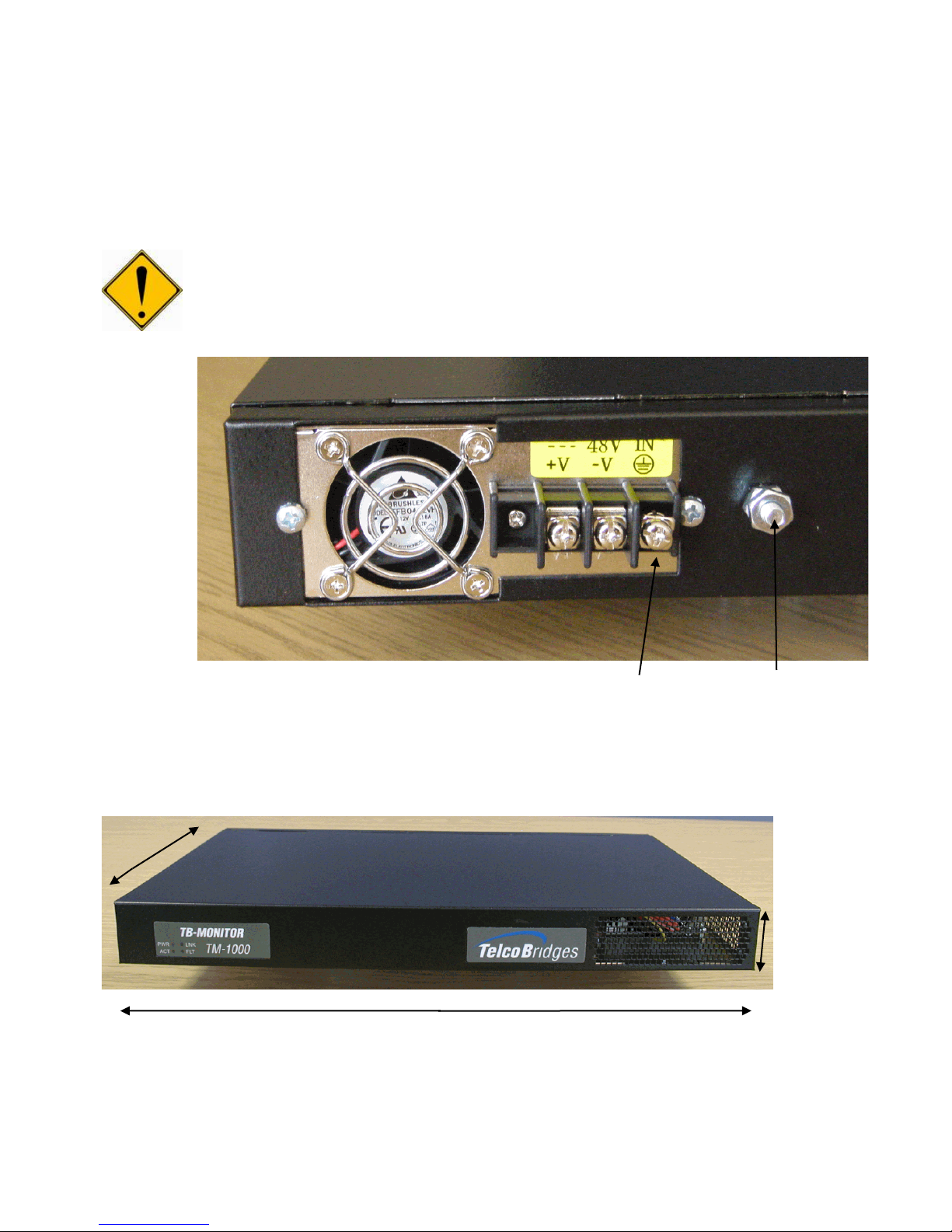
Figure 2TM-1000 rear view DC Power supply option and ground post
2.1. TM-1000 Front View and Physical Dimensions
Figure 3TM-1000 Front View
W
H
L
Ground
Chassis Ground

TM-1000 Installation Guide for Toolpack
CONFIDENTIAL
9000-00015-1A
Page 10 of 32
Copyright © 2003-2016 by TelcoBridges
Dimension
Inches
Centimeters
Length
17 ¼
43.8
Width
11
27.9
Height
1 ¾
3.8
Table 1 TM-1000 dimension
Unit Weight: 9 LB or 4.1 Kg
2.2. TM-1000 Environmental Specifications
Operating temperature
0° to 40°C (32° to 104°F)
Storage temperature
-20° to 70°C (-4° to 158°F)
Operating relative humidity
10% to 85% non-condensing
Storage relative humidity
10% to 85% non-condensing
Table 2TM-1000 environmental specifications
When selecting an installation site, observe these guidelines:
•Cabling is away from sources of electrical noise, such as radios, power lines, and fluorescent lighting fixtures
•Clearance to the TM-1000 is such that:
•Airflow around the TM-1000 and through the vents is unrestricted
•Front-panel LEDs can be easily read
•Access to ports is sufficient for unrestricted cabling
•AC power cord can reach from the AC power outlet to the connector on the TM-1000. The power outlet
must be accessible at all times because it serves as the main method to disconnect power from the TM-
1000
9000-00015-1A
CONFIDENTIAL
TM-1000 Installation Guide for Toolpack
Copyright © 2003-2016 by TelcoBridges
Page 11 of 32
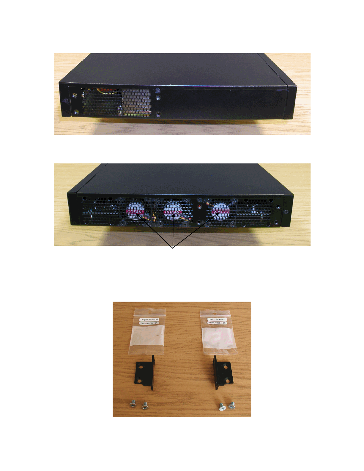
2.3. TM-1000 right side view
Figure 4TM-1000 right side view
2.4. TM-1000 left side view
Figure 5TM-1000 left side view with three cooling fans
2.5. TM-1000 rack-mounting brackets and screws
Figure 6TM-1000 left and right side bracket kit
Cooling fans
TM-1000 Installation Guide for Toolpack
CONFIDENTIAL
9000-00015-1A
Page 12 of 32
Copyright © 2003-2016 by TelcoBridges
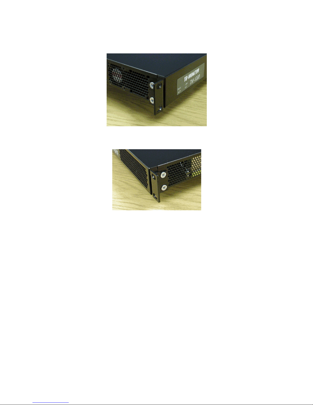
2.5.1. TM-1000 with left side bracket installed
Figure 7TM-1000 left side right angle
2.5.2. TM-1000 with right side bracket installed
Figure 8TM-1000 right side right angle

9000-00015-1A
CONFIDENTIAL
TM-1000 Installation Guide for Toolpack
Copyright © 2003-2016 by TelcoBridges
Page 13 of 32
2.6. TM-1000 LED Description
Figure 9 TM-1000 Front View LED description
Item
Color
Description
Item
Color
Description
PWR
None
No power
LNK
None
Not finished restarting the TM-
1000
Red
Power fault
Red
Ethernet port disconnected
Green
Power good
Green
Ethernet port connected
ACT
None
Trunk not allocated
FLT
None
Internal debug status report
Red
Tapping resource not
available
Red
Internal debug status report
Solid Green
Trunk allocated
Green
Internal debug status report
Blink Green
Trunk activity
Table 3TM-1000 Front LED status
2.7. TM-1000 Rear View
Figure 10 TM-1000 rear view
TM-1000 Installation Guide for Toolpack
CONFIDENTIAL
9000-00015-1A
Page 14 of 32
Copyright © 2003-2016 by TelcoBridges
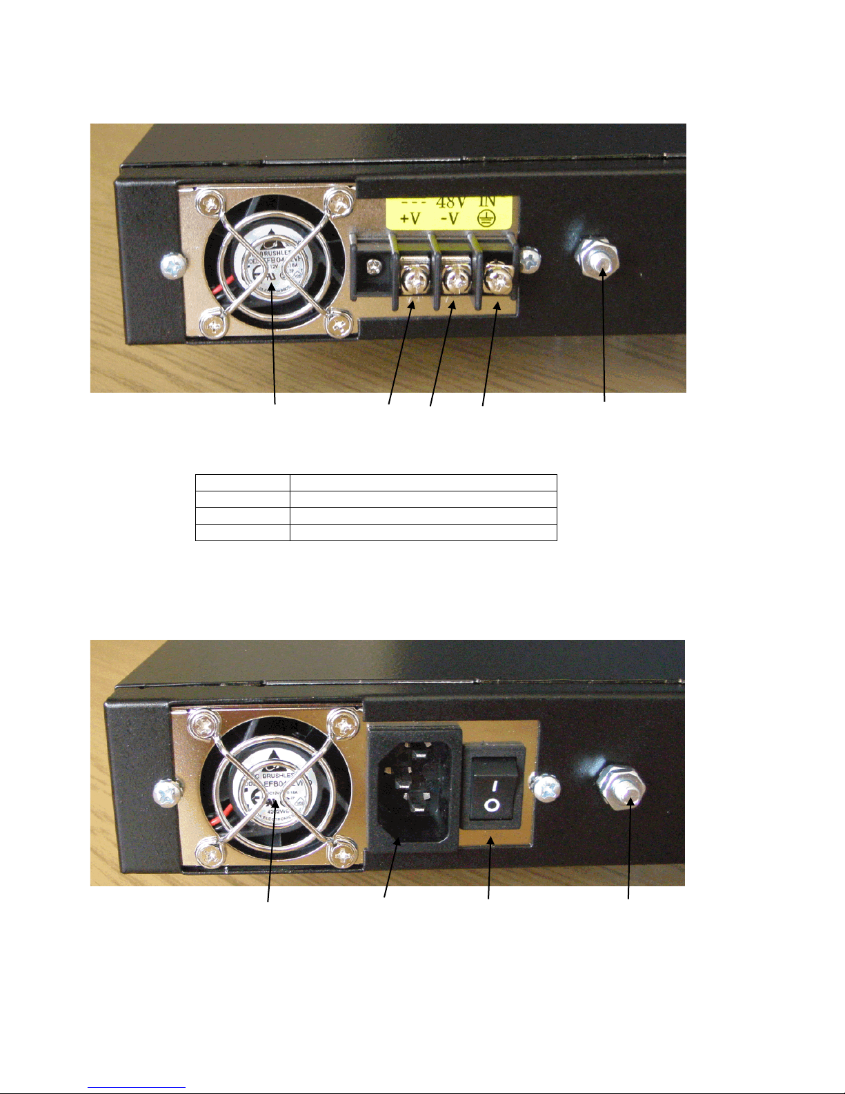
2.8. TM-1000 DC Power Supply Option
Figure 11 TM-1000 rear view DC Power supply option and ground post
Table 4TM-1000 DC Power supply
You need a Philips screwdriver to tighten the cable tab connections
2.8.1. TM-1000 AC Power Supply Option Description
Figure 12 TM-1000 rear view AC Power supply option, On/Off switch and ground post
Power input from 100 to 240V AC, 47 to 63 Hz with 4 Amp maximum load. This is an auto detect AC power input.
Contact ID
Description
+V
DC Power return
-V
-40 to -65V DC input with 9A max load
GND
Earth ground
+V
-V
GND
Chassis GND
Cooling fan
Cooling fan
PC standard AC
power input
Chassis GND
Power ON/Off switch
9000-00015-1A
CONFIDENTIAL
TM-1000 Installation Guide for Toolpack
Copyright © 2003-2016 by TelcoBridges
Page 15 of 32
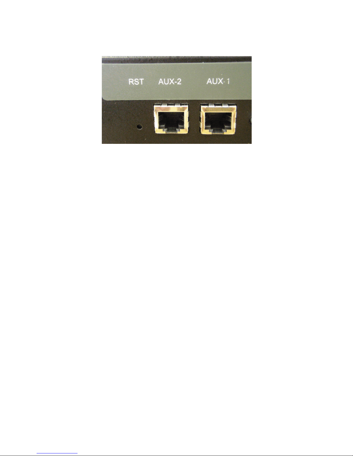
2.9. TM-1000 Reset, Auxiliary 1 and 2 Description
Figure 13 TM-1000 rear view Reset and auxiliary feature
•You will need to insert a pin in the hole to reach the reset button
oIf you quick press and release the reset button the TM-1000 will restart.
oIf you hold on the reset button for at least five seconds, the TM-1000 will shut down.
oIf you hold on the reset button for at least five seconds after a shut down, the TM-1000 will restart.
•Aux-1 and Aux-2 RJ-45 connectors are used for optional features. These features are not implemented yet. Do
not use Aux-1 and Aux-2 connectors.

TM-1000 Installation Guide for Toolpack
CONFIDENTIAL
9000-00015-1A
Page 16 of 32
Copyright © 2003-2016 by TelcoBridges
2.10.TM-1000 Serial Port RS-232
Figure 14 TM-1000 rear view RS-232 Link
Figure 15 TM-1000 RS-232 Pin Out
Pin number
Description
1
Not connected
2
Receive signal (Rx)
3
Transmit signal (Tx)
4
Not connected
5
Ground
6
Not connected
7
Not connected
8
Not connected
9
Not connected
Table 5TM-1000 RS-232 DB-9 pin out

9000-00015-1A
CONFIDENTIAL
TM-1000 Installation Guide for Toolpack
Copyright © 2003-2016 by TelcoBridges
Page 17 of 32
2.11.TM-1000 Ethernet 1 and 2
Figure 16 TM-1000 rear view Ethernet 10/100/1G ports
Item
Led color
Description
SPD
Off
Ethernet port connected 100M
Yellow
Ethernet port connected 1G
LNK
Off
Ethernet port disconnected
Solid Green
Ethernet port connected
Blink Green
Ethernet activity on the connected port
Table 6TM-1000 Ethernet LED description
Connector front view
8 1
Pin number
Description
1
Bi-directional pair A+
2
Bi-directional pair A-
3
Bi-directional pair B+
4
Bi-directional pair C+
5
Bi-directional pair C-
6
Bi-directional pair B-
7
Bi-directional pair D+
8
Bi-directional pair D-
Table 7TM-1000 Ethernet RJ-45 pin out
Each Ethernet port has a speed auto detect option of 1 Gbps.
2.12.Network Protocol and Standards Compatibility
•IEEE 802.3z/ab 1000Base-T
TM-1000 Installation Guide for Toolpack
CONFIDENTIAL
9000-00015-1A
Page 18 of 32
Copyright © 2003-2016 by TelcoBridges
2.13.TM-1000 E1/T1/J1 Input Cable Connectors
Figure 17 TM-1000 rear view SCSI-3 input connection
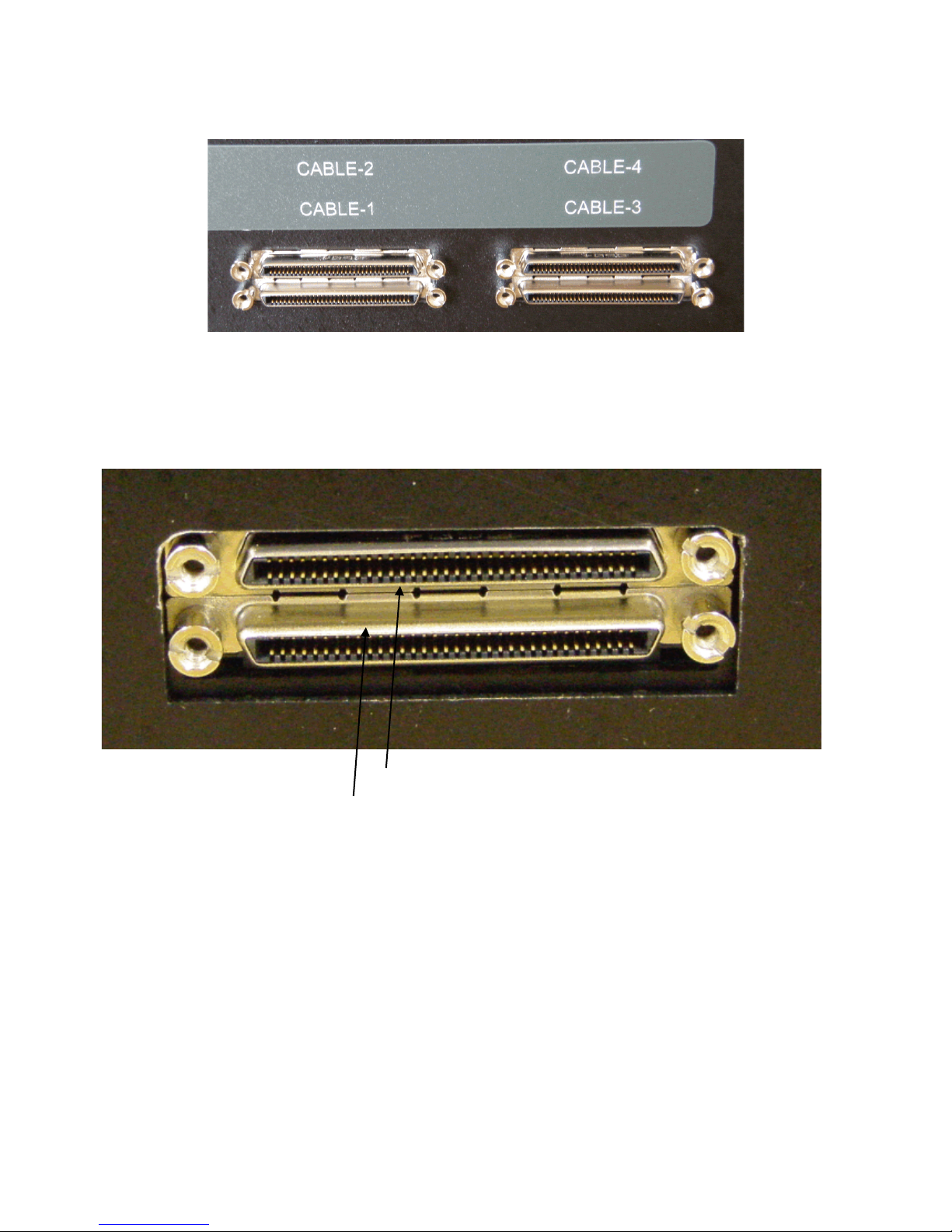
2.14.Patch panel SCSI-3 connector
Figure 18 Patch panel SCSI-3 connector
•The lower SCSI-3 connector is always connected with patch panel number 1 to 16.
•The lower SCSI-3 connector must always be connected with Cable-1 or Cable-3 of the TM1000.
•The upper SCSI-3 connector is always connected with patch panel number 17 to 32.
The upper SCSI-3 connector must always be connected with Cable-2 or Cable-4 of the TM1000.
Plug only with Cable-1 or Cable-3 of the TM-1000
Plug only with Cable-2 or Cable-4 of the TM-1000

9000-00015-1A
CONFIDENTIAL
TM-1000 Installation Guide for Toolpack
Copyright © 2003-2016 by TelcoBridges
Page 19 of 32
TM-1000 cable trunk input:
RJ-45 Pin 1-2 input
RJ45 Pin 4-5 input
Cable-1
Trunk 1-16
Trunk 65-80
Cable-2
Trunk 17-32
Trunk 81-96
Cable-3
Trunk 33-48
Trunk 97-112
Cable-4
Trunk 49-64
Trunk 113-128
Table 8TM-1000 SCSI-3 trunk cable input

TM-1000 Installation Guide for Toolpack
CONFIDENTIAL
9000-00015-1A
Page 20 of 32
Copyright © 2003-2016 by TelcoBridges
3. Patch panel with 32 x RJ-45
This patch panel supports 64 trunk inputs (32 full-duplex trunks).
3.1. Patch panel front view
Figure 19 Patch panel front view
3.2. Patch panel rear view
Figure 20 Patch panel rear view
Pull up the cover
to remove
2 x Philips screws
Table of contents


