Telecard R-1150-00 User manual

HF Radio R-1150-00
Operation Manual
ААНЗ.464414.001.61 РЭ
Type А

ААНЗ.464414.001-03.61 РЭ p.2
Contents
1
Overview
6
1.1
Description and performance of the radio
6
1.1.1
Purpose of the radio
6
1.1.2
Technical Specifications
7
1.1.2.1
Specifics of Radio Operation
7
1.1.2.2
Technical Specifications
8
1.1.3
Configuration
13
1.1.3.1
Component parts of the radio, names and notations
13
1.1.3.2
Installation of the major components of the R-1150-01 version
29
1.1.3.3
Installation of the major components of the R-1150-02 version
33
1.1.4
Setting and Performance
37
1.1.4.1
Radio operation in the transmit mode
37
1.1.4.2
Radio operation in the receive mode
38
1.1.4.3
Radio operation during the Antenna Coupler setting
38
1.1.4.4
Radio performance during the radio test control
39
1.1.4.5
Radio capability in different modes of operation
39
1.1.4.6
Preset parameters overview
41
1.1.4.7
Quick change of parameter values
43
1.1.4.8
«AM»mode
44
1.1.4.9
«DM»mode
44
1.1.4.10
Operation in digital telephony mode
44
1.1.4.11
«ALE» mode
44
1.1.4.12
FHSS mode
48
1.1.4.13
Synchronization in FHSS mode
49
1.1.4.14
Radio interconnection with the peripherals
50

ААНЗ.464414.001-03.61 РЭ p.3
Operation and Maintenance Manual (hereinafter referred to as Manual) helps
personnel to study how to operate and maintain the HF Radio R-1150 (hereinafter referred to
as the radio). It provides detailed description of its component parts as well as its operating
rules. The Operation Manual describes the following:
Technical Specifications for the radio;
Configuration and design;
Equipment and operation;
Maintenance service;
Servicing;
Storage conditions;
Transportation;
Final disposal.
The Operation and Maintenance Manual is intended for qualified specialists who
have special training in operation of the radio of the given type and on-the-air operation and
skills in PC operation.
ATTENTION!
Serious electrical shock hazards can exist during radio operation.
Do not open any operating units during radio performance. The urgency of execution
is not the reason to violate this requirement.
Do not touch the bared electrical feed circuits. Antenna output is of special danger,
where voltage can be of several hundred volts. Therefore, while operating the radio you should
remember that the ANTENNA output connector of the unit is uninsulated. Do not touch the
ANTENNA output connector, as it may result in electrical hazard.

ААНЗ.464414.001-03.61 РЭ p.4
1 Overview
1.1 Description and performance of the radio
1.1.1 Purpose of the radio
The radio is intended to provide bidirectional antijam telegraphic-telephone radio
communication and to transmit data through the radio channels of the HF wave band.
The radio is produced in the following versions:
R-1150-00 - 150 W HF Tactical Radio;
R-1150-01 - 400 W HF Tactical Radio;
–R-1150-02 –1000 W HF Tactical Radio.
The radio operates in the following environmental conditions:
temperature of ambient environment is in the range from 253 to 328 К(from minus
20ºC to 55ºC);
relative humidity is not more than 95 % under the temperature of not more than 313
К(40ºC);
relative humidity is not more than 60 to 113 кPа(from 450 to 850 mmHg).
The R-1150 radio meets the requirements, specified for the equipment of the 1.7, 1.8,
1.10 groups (with the exception of lowered operating temperature), according to the ГОСТ В
20.39.304-76 National Standard.
The R-1150-01, R-1150-02 radios meet the requirements, specified for the equipment
of the 1.7, 1.8 groups (with the exception of lowered operating temperature) according to the
ГОСТ В 20.39.304-76 National Standard.
Antenna Coupler, as the component part of the radio is produced in the following
versions AH210-01, AH210-10 and meets the requirements, specified for the equipment of the
1.14 group in compliance with ГОСТ В 20.39.304-76 National Standard.
The R-1150-00 radio provides operation at the whip antennas of 4 –6 m length.
The R-1150-01, R-1150-02 radios provide operation at the whip antennas of 4 –10 m
length.
The radio provides voice communications via the handset or ААНЗ.468624.001
headset.
The radio is compatible with radios of other types, which supports the same operating
frequencies and use the same emission types.
The radio is intended to be installed inside the mobile facilities. The Antenna Coupler is
designed to be installed inside the objects or outside in the antenna racks. The Antenna
Coupler should be in the distance of not more than 75 m from the radio.

ААНЗ.464414.001-03.61 РЭ p.5
Heat emission of the radio should not exceed:
for R-1150-00 version:140 W in the receive mode and 750 W in the transmit mode;
for R-1150-01 version:140 W in the receive mode and 1200 W in the transmit mode;
for R-1150-02 version:140 W in the receive mode and 3200 W in the transmit mode.
1.1.2 Technical Specifications
1.1.2.1 Specifics of Radio Operation
When the radio is used properly, it has the following capability:
support of the digital techniques of technical data masking;
compatibility with DTEs, which provide secure communications;
variable level of output power (four power gradations, namely, 100%, 50; 25%
12,5%: 100, 50; 25; 12,5%);
operation in "ALE" mode (adaptive selection of the working channel with automatic
link establishment mode) in compliance with MIL-STD-188-141B;
operation in digital telephony mode (digital voice), using MELP voice conversion
techniques;
operation in compliance with Data Link Layer Protocol (ARQ), which provides
automatic request for repeat or retransmission;
Electronic Protection Measures (EPM) protect communications from hostile
interference using the FHSS mode;
an embedded Global Positioning System (GPS) receiver option provides the
accurate time-of-day and local position information;
the embedded self-testing capability provides the radio operator with the information
about the radio operability;
operation in the single-frequency simplex mode , as well as double-frequency
simplex mode;
operation in the radio silence mode;
24 hour continuous operation capability роботи;
remote control from the individual terminal in compliance with the RS-232 protocol;
remote control from the individual terminal in compliance with the Ethernet protocol;
operation in the LAN network in compliance with the Ethernet protocol; data
communications with 50 to 19200 bps rate due to built-in modems that support operation in
compliance with protocols ARQ, STANAG 4444, MIL-STD-188-110B, APPENDIX F,
STANAG4539/MIL-STD-188-110B, MIL-STD-188-110A, § 5.3 and FSK;

ААНЗ.464414.001-03.61 РЭ p.6
protection from faulty voltage sign switching on;
availability of memory support battery, intended to store previously recorded
information in the internal memory of the radio after it has been powered off;
detachable control unit with liquid crystal display provides easy and flexible radio
control;
ability of remote control from a remote control unit (hereinafter - the RCU) and PC.
1.1.2.2 Technical Specifications
1.1.2.2.1 Basic technical specifications of the radio are presented in Table 1.
Table 1 –Basic technical specifications
Parameter
Value
1
2
Frequency range, kHz
1500 to 29999,99
Channel Spacing, Hz
10
Frequency Stability
3∙10-7
Emission Modes (receiving)
A1A, J3E, B8E, Н3E, А3Е,
F1B in modem FSK mode
Emission Modes ( transmission)
A1A, J3E, B8E, Н3E, F1B in
modem FSK mode
Receiver Sensitivity: J3E (single sideband, upper and
lower) , for 10d SINAD, µV, not worse
1,0
Receiver Sensitivity: А1А for 10 dB SINAD, µV, not
worse
0,5
Receiver Sensitivity : F1B in FSK of the modem, µV, not
worse
1,0
Image Rejection, dB, not less
80
IF Rejection, dB, not less
80
Table 1 (continued)
1
2
Receiver IF Bandwidth, Hz
300, 1100, 2400, 2750, 3100,
6000
Receiver amplitude -frequency characteristic unevenness:
J3E (lower and upper sideband), dB, not more
3
Receiver non-linear distortions: J3E, %, not more
5

ААНЗ.464414.001-03.61 РЭ p.7
AGC range (manually selected), dB, not less
40
Receiver AGC range (automatically selected), dB, not
less
100
AGC time-activation constant, ms, not more
12
AGC time-release constant gradation, ms, not less
100, 750, 1000, 4000
Receiver output tone frequency: А1А, Hz
1000 ± 100
Receiver PEP output: А1А, J3E at 50 ohm, W
- for 150W R-1150-00 radio:
100 % capacity
107 to 214
50 % capacity
53,5 to 107
25 % capacity
27 to 53,5
12,5 % capacity
13,5 to 27
- for 400W R-1150-01 radio:
100 % capacity
318 to 504
50 % capacity
159 to 252
25 % capacity
80 to 126
12,5 % capacity
40 to 63
- for 1000W R-1150-02 radio:
100 % capacity
795 to 1260
50 % capacity
397 to 630
25 % capacity
199 to 315
12,5 % capacity
99 to 158

ААНЗ.464414.001-03.61 РЭ p.8
Table 1 (continued)
1
2
Transmitter Carrier level : J3E, dB, not more
40
Transmitter sideband (unused) : J3E,dB, not more
40
The radio provides operation at whip antennas. Antenna
length, m
4 to 6
- for 150W R-1150-00 radio
4 to 6
- for 400W R-1150-01 radio
4 to 10
- for 1000W R-1150-02 radio
4 to 10
Alignment time, s, not more
- for 150W R-1150-00 radio
2,5
- for 400W R-1150-01 radio
5
- for 1000W R-1150-02 radio
5
Net presets, not less
400
Harmonic suppression, dB, not more
- for 150W R-1150-00 radio
minus 50
- for 400W R-1150-01 radio
minus 60
- for 1000W R-1150-02 radio
minus 60
Transmitter non-linear distortion level :J3E, dB, not more
30
Data Interface
RS-232, ETHERNET
Digital voice transmission rate, bps
1200, 2400
Readiness time after powering on the radio, min, not
more
5
Input power :
- for R-1150-00 radio
On-board 27V DC Power
Supply Unit with deviations
from 21,6V to 30,5V
- for R-1150-01 radio
100 to 240 V AC
network with
frequency from 47 to 63 Hz
- for R-1150-02 radio
100 to 240 V AC
network with
frequency from 47 to 63 Hz

ААНЗ.464414.001-03.61 РЭ p.9
1.1.2.2.2 The radio is equipped with the following data input/output:
input to connect the handset or the headset;
input for intercom system connection (hereinafter referred to as INTERCOM);
line input/output;
input to connect the telegraph key;
input to connect the equipment on RS-232 interface.
1.1.2.2.3 The radio is equipped with the input for GPS receiver connection. GPS
receiver output data provide radio position reporting, and can be used to synchronize the
receiver while operating in the FHSS mode
1.1.2.2.4 The radio is equipped with the PC input to be controlled remotely from the
PC.
1.1.2.2.5 The radio is equipped with the input to be connected to the local
area network (LAN). Such connection provides data transmission and control of the radio from
the remote PC. Remote control and data transmission are provided by means of the
ClientWinSocket (TCP/IP protocol). The ServerWinSocket station supports not more than 5
client sockets.
1.1.2.2.6 The radio is capable to operate in the standby reception mode. The mode
provides radio silence of the radio.
1.1.2.2.7 While operating in the ALE mode, the radio supports the following types of
operation:
channel scanning;
channel sensing;
individual call;
network call;
group call;
Table 1 (continued)
1
2
Current consumption:
- for R-1150-00 radio from the on-board power source,
W, not more
1000
- for R-1150-01 radio from the AC network, W, not more
1550
- for R-1150-02 radio from the AC network, W, not
more
3500

ААНЗ.464414.001-03.61 РЭ p.10
selective call;
automatic message display.
While operating in ALE mode the radio provides the following settings:
number of scanned channels –not more than 100;
channel scanning rate –2 or 5 times per second;
number of station’s serviceable home addresses –not more than 20;
number of station’s serviceable network addresses –not more than 20;
number of serviceable individual addresses –not more than 120;
number of channel groups –not more than 5;
number of channels in the group –not more than 16.
1.1.2.2.8 While operating on fixed frequencies and in the ALE mode the radio
supports data transmission due to internal modem, complied with the standard, and with the
settings, presented in Table 2.
Table 2 –Buit-in data modem settings
Standard notation
Modulation coding
Data rate, bps
MIL-STD-188-110B,
APPENDIX F
E
PSK/QAM
9600, 12800, 16000, 19200
STANAG4539 /
MIL-STD-188-110B
E
PSK/QAM
3200, 4800, 6400, 8000, 9600
N
12800
MIL-STD-188-110A, §5.3
E
PSK
75, 150, 300, 600, 1200, 2400
N
4800
FSK програмувальна
FSK
50, 75, 100, 150, 300, 600
Note –The abbreviations «E» and «N» in the table stand for:
- E –information in the modem is encoded;
- N - information in the modem is not encoded.
1.1.2.2.9 Frequency hopping period in FHSS mode is 112,5 ms.
1.1.2.2.10 Voice transmission in FHSS mode is done in digital form with 1200 or 2400
bps rate. Data rate is selected by the radio operator. While operating with frequency hopping,
the radio supports data transmission due to the built-in modem, complied with the STANAG
4444 with 75, 150, 300, 600, 1200 and 2400 bps rates.
1.1.3 Configuration
1.1.3.1 Component parts of the radio, names and notations
The component parts of the radio are presented:

ААНЗ.464414.001-03.61 РЭ p.11
for R-1150-00 version in Table 3;
for R-1150-01 version in Table 3а;
for R-1150-02 version in Table 3b.
Table 3 –Component parts of the R-1150-00 radio
Name of the device, component part
Notation
Number
of items/
sets
Notes
1
2
3
4
AH300 Transceiver Unit
ААНЗ.464511.011.61
1
Power supply DC-DC AH570
ААНЗ.436537.006.61
1
AV100 Fill Gun
ААНЗ.468339.007.61
1
WV355 Control unit
ААНЗ.468389.009.61
1
Lightweight Headset
ААНЗ.468624.001
1
**
Lightweight Handset HHS-250MICAM
1
Loudspeaker АН420 with
ААНЗ.467291.004.61
1
AH420 UX1 cable
ААНЗ.685692.335
1
**
AH210-01 Antenna Coupler
АЮХА.468567.026 ТУ
1
АН220-01 Power Amplifier
АЮХА.468733.010 ТУ
1
Dipole antenna KUA-35/6-400
Antenna AD-4
Assembly parts set complete with:
ААНЗ.464941.021.61
1
- shock mount АН300
ААНЗ.301222.003.61
1
- shock mount АН220-01
ААНЗ.301222.004.61
1
- shock mount АН570
ААНЗ.301222.010.61
1
- bracket AH300
ААНЗ.301561.038.61
2
**
- bracket AH220-01
ААНЗ.301561.039.61
2
**
- bracket AH570
ААНЗ.301561.040.61
2
**
- isolator
ААНЗ.757513.215
2
Table 3 (continued)
1
2
3
4
- R-1150 UX12 cable
ААНЗ.685692.355
1
- R -1150 UX7 cable
ААНЗ.685623.040.61
1

ААНЗ.464414.001-03.61 РЭ p.12
- R -1150 UX1 cable
ААНЗ.685623.041.61
1
- R -1150 UX4 cable
ААНЗ.685623.042.61
1
*
- R-1150 UX5 cable
ААНЗ.685623.043.61
1
*
- R-1150 UX8 cable
ААНЗ.685623.044.61
1
*
- R-1150 UX3 cable
ААНЗ.685661.097.61
1
*
- R-1150 UX9 cable
ААНЗ.685661.152.61
1
- R-1150 UX6 cable
ААНЗ.685661.153.61
1
*
- R-1150 UX10 cable
ААНЗ.685691.200.61
1
*
- R-1150 UX11 cable
ААНЗ.685691.203.61
1
*
- R-1150-03 UX1 cable
ААНЗ.685623.050.61
1
- «АC-А» signal cable
ААНЗ.685669.001.61
1
- М6-6gх16.58.019 ГОСТ 7805-70 bolt
16
- М5-6gх20.21.12Х18Н10Т GOST 11738-
84 screw
2
- М6-6gх16.88.019 GOST 11738-84 screw
8
- М6-6gх20.88.019 GOST 11738-84 screw
12
- М5-6Н 21.12Х18Н10Т GOST ГОСТ
5927-70 nut
2
- М6-6Н 21.12Х18Н10Т GOST 5927-70 nut
12
- 6 65Г 016 GOST 6402-70 washer
16
- 5.21 GOST 11371-78 washer
2
- 6.21 GOST 11371-78 washer
36
- 5.A2 DIN 6798A washer
2
- 6.A2 DIN 6798A washer
20
Spare parts set complete with:
1
- «АC-А» signal cable
ААНЗ.685669.001.61
1

ААНЗ.464414.001-03.61 РЭ p.13
Table 3 (continued)
1
2
3
4
packing
1
Maintenance documentation package in
compliance with ААНЗ.464414.001 ВЭ
-
HF Radio. Software product
-
1
CD-R
disc
Notes
1 *cable length L in accordance with the Table 4 (specified while ordering)
2 ** Supply is specified on order.
Table 3a –Major components for HF radio R-1150-01
Product/component name
Designation design
document
Amount,
items
Note
1
2
3
4
Radio transmitting device consisting of:
ААНЗ.464424.040
1
- Transceiver АН300
ААНЗ.464511.011.61
1
- Control unit WV355
ААНЗ.468389.009.61
1
- Power amplifier АН220-04
АЮХА.468733.010 ТУ
1
- Rack mounting АН110-400
ААНЗ.301212.003
1
Fill gun AV100
ААНЗ.468339.002-
01.61
1
Lightweight Headset
ААНЗ.468624.001
1
**
Handset HHS-250MICAM
-
1
**
Antenna coupler АН210-10
АЮХА.468567.026 ТУ
1
Loudspeaker AН420
ААНЗ.467291.004.61
1
**
Dipole antenna KUA-35/6-400
-
1
**
Antenna AD-4
-
1
**

ААНЗ.464414.001-03.61 РЭ p.14
Continued table 3a
1
2
3
4
Assembly parts set:
ААНЗ.464941.028
1
- bracket
ААНЗ.301561.019
1
- bracket (RCU)
ААНЗ.301568.016
1
- latch
-
2
- cable R-1150 UX12
ААНЗ.685692.355
1
**
- cable R-1150 UX7
ААНЗ.685623.040.61
1
- cable R-1150 UX1
ААНЗ.685623.041.61
1
- cable R-1150 UX4
ААНЗ.685623.042
1
- cable R-1150 UX5
ААНЗ.685623.043
1
- cable R-1150 UX8
ААНЗ.685623.044-03
1
- cable R-1150 UX3
ААНЗ.685661.097
1
- cable R-1150 UX9
ААНЗ.685661.152
1
- cable R-1150 UX6
ААНЗ.685661.153-03
1
- cable R-1150 UX14
ААНЗ.685631.011
1
- вилка FGN.0F.305.CLC (LEMO)
1
- вилка FGN.2F.319.CLC (LEMO)
1
- вилка FGP.2F.319.CLC (LEMO)
1
Packing
ААНЗ.305632.041.61
1
Packing
ААНЗ.305632.045.61
1
Set of operational documentation
1
HF radio. Software products
-
1
CD-R disc
Note
1 * Cable length L according to Table 4 indicated when ordering.
2 ** Delivery option and is subject to the execution order

ААНЗ.464414.001-03.61 РЭ p.15
Table 3b –Major components for HF radio R-1150-02
Product/component name
Designation design
document
Amount,
items
Note
1
2
3
4
Radio transmitting device consisting of:
ААНЗ.464424.041.61
1
- Transceiver АН300
ААНЗ.464511.011.61
1
- Control unit WV355
ААНЗ.468389.009.61
1
- Power amplifier АН220-10
АЮХА.468733.010 ТУ
1
- Power Supply AH500-10
АЮХА.436617.001
- Rack mounting АН110-1000
ААНЗ.301212.004
1
Fill gun AV100
ААНЗ.468339.002-
01.61
1
Lightweight Headset
ААНЗ.468624.001
1
**
Handset HHS-250MICAM
-
1
**
Antenna coupler АН210-10
АЮХА.468567.026 ТУ
1
Loudspeaker AН420
ААНЗ.467291.004.61
1
**
Dipole antenna KUA-35/6-1000
-
1
**
Antenna AD-4
-
1
**
Assembly parts set:
ААНЗ.464941.027.61
1
- bracket (RCU)
ААНЗ.301568.016
1
- latch
-
2
- cable R-1150 UX12
ААНЗ.685692.355
1
- cable R-1150 UX7
ААНЗ.685623.040.61
1
- cable R-1150 UX1
ААНЗ.685623.041.61
1
- cable R-1150 UX4
ААНЗ.685623.042.61
1
- cable R-1150 UX5
ААНЗ.685623.043.61
1
- cable R-1150 UX8
ААНЗ.685623.044-
03.61
1
- cable R-1150 UX3
ААНЗ.685661.097.61
1
- cable R-1150 UX9
ААНЗ.685661.152.61
1
- cable R-1150 UX6
ААНЗ.685661.153-
03.61
1
- cable R-1150 UX12
ААНЗ.685631.009.61
1

ААНЗ.464414.001-03.61 РЭ p.16
Continued table 3b
1
2
3
4
- cable R-1150 UX13
ААНЗ.685631.010.61
1
- plug FGN.0F.305.CLC (LEMO)
1
- plug FGN.2F.319.CLC (LEMO)
1
- plug FGP.2F.319.CLC (LEMO)
1
Packing
ААНЗ.305632.040.61
1
Packing
ААНЗ.305632.044.61
1
Set of operational documentation
1
HF radio. Software products
ААНЗ.464949.005
1
CD-R disc
Note
1 * Cable length L according to Table 4 indicated when ordering.
2 ** Delivery option and is subject to the execution order
The major components of the R-1150 radio are the following:
АН300 Transceiver Unit;
–WV355 Control Unit;
АН220-01 Power Amplifier;
АН210-01 Antenna Coupler;
DC Power Supply Unit.
The major components of the Р-1150-01 version are the following:
АН300 Transceiver Unit;
WV355 Control Unit;
АН220-04 Power Amplifier;
АН210-10 Antenna Coupler.
The major components of the Р-1150-02 version are the following:
АН300 Transceiver Unit;
WV355 Control Unit;
АН220-10 Power Amplifier;
АН210-10 Antenna Coupler;
AH500-10 Power Supply Unit.
To install the major parts of the radio into the mobile object while assembling the radio
for proper use, the assembly parts set is used.

ААНЗ.464414.001-03.61 РЭ p.17
Connection cables are of wide variety of lengths to enable the radio mounting on
mobile objects with different assembly. The notation of cables, available in the delivery set,
and are made while ordering, for different objects of installation, are presented in Table 4, 4а,
4b.
Table 4 –Variants of cable length for the R-1150-00 version
Cable notations
Length of the cables for different design, m
0
1
2
3
4
5
6
7
8
9
ААНЗ.685692.355 R-1150 UX12
1,0
-
-
-
-
-
-
-
-
-
ААНЗ.685623.040.61 R-1150 UX7
1,62
-
-
-
-
-
-
-
-
-
ААНЗ.685623.041.61 R-1150 UX1
1,62
-
-
-
-
-
-
-
-
-
ААНЗ.685623.042.61 R-1150 UX4
10
15
20
25
30
35
40
50
60
75
ААНЗ.685623.043.61 R-1150 UX5
2
4
6
8
10
-
-
-
-
-
ААНЗ.685623.044.61 R-1150 UX8
5
3
0,9
-
-
-
-
-
-
-
ААНЗ.685661.097.61 R-1150 UX3
10
15
20
25
30
35
40
50
60
75
ААНЗ.685661.152.61 R-1150 UX9
1,62
-
-
-
-
-
-
-
-
-
ААНЗ.685661.153.61 R-1150 UX6
5
3
0,35
-
-
-
-
-
-
-
ААНЗ.685691.200.61 R-1150 UX10
3
0,6
-
-
-
-
-
-
-
-
ААНЗ.685691.203.61 R-1150 UX11
3
0,6
-
-
-
-
-
-
-
-
Table 4а –Variants of cable length for the R-1150 -01 version
Cable notations
Length of the cables for different design, m
0
1
2
3
4
5
6
7
8
9
ААНЗ.685692.355 R-1150 UX12
1,0
-
-
-
-
-
-
-
-
-
ААНЗ.685623.040.61 R-1150 UX7
1,62
-
-
-
-
-
-
-
-
-
ААНЗ.685623.041.61 R-1150 UX1
1,62
-
-
-
-
-
-
-
-
-
ААНЗ.685623.042.61 R-1150 UX4
10
15
20
25
30
35
40
50
60
75
ААНЗ.685623.043.61 R-1150 UX5
2
4
6
8
10
-
-
-
-
-
ААНЗ.685623.044.61 R-1150 UX8
0,9
-
-
-
-
-
-
-
-
-
ААНЗ.685661.097.61 R-1150 UX3
10
15
20
25
30
35
40
50
60
75
ААНЗ.685661.152.61 R-1150 UX9
1,62
-
-
-
-
-
-
-
-
-
ААНЗ.685661.153.61 R-1150 UX6
1,1
-
-
-
-
-
-
-
-
-
ААНЗ.685631.011.61 R-1150
UX14
3
5
-
-
-
-
-
-
-
-
Таблиця 4b –Variants of cable length for the R-1150-02 version
Cable notations
Length of the cables for different design, m

ААНЗ.464414.001-03.61 РЭ p.18
0
1
2
3
4
5
6
7
8
9
ААНЗ.685692.355 R-1150 UX12
1,0
-
-
-
-
-
-
-
-
-
ААНЗ.685623.040.61 R-1150 UX7
1,62
-
-
-
-
-
-
-
-
-
ААНЗ.685623.041.61 R-1150 UX1
1,62
-
-
-
-
-
-
-
-
-
ААНЗ.685623.042.61 R-1150 UX4
10
15
20
25
30
35
40
50
60
75
ААНЗ.685623.043.61 R-1150 UX5
2
4
6
8
10
-
-
-
-
-
ААНЗ.685623.044.61 R-1150 UX8
0,9
-
-
-
-
-
-
-
-
-
ААНЗ.685661.097.61 R-1150 UX3
10
15
20
25
30
35
40
50
60
75
ААНЗ.685661.152.61 R-1150 UX9
1,62
-
-
-
-
-
-
-
-
-
ААНЗ.685661.153.61 R-1150 UX6
1,1
-
-
-
-
-
-
-
-
-
ААНЗ.685691.203.61 R-1150
UX12
0,6
-
-
-
-
-
-
-
-
-
ААНЗ.685691.203.61 R-1150
UX13
3
5
-
-
-
-
-
-
-
-
1.1.3.1.1 Installation of the radio major components
1.1.3.1.2 Installation of the АН300 Transceiver
The Transceiver Unit is installed into the mobile objects, using shock mount АН300,
brackets АН300, fasteners.
The order of installation:
Install the transceiver unit onto the shock-absorbing rack (put the brackets, using the
fasteners, onto the rack in advance, if necessary) and fix by the locks.
The АН300 Transceiver Unit assembly drawing is presented in Figure 1.
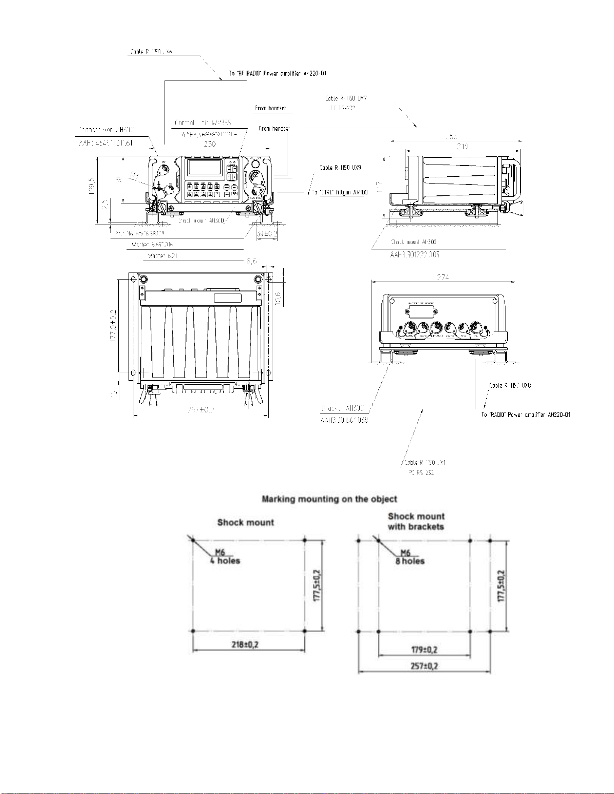
ААНЗ.464414.001-03.61 РЭ p.19
Figure 1 –АН300 Transceiver Unit Assembly Drawing

ААНЗ.464414.001-03.61 РЭ p.20
Note –There is no need to use brackets while installing the Transceiver Unit into the
mobile objects.
1.1.3.1.3 Installation of the Power Amplifier AH220-01
The Power Amplifier is installed into the mobile objects, using the AH220-01 shock
mount, PA brackets, and fasteners.
The order of installation:
Install the Power Amplifier onto the shock-absorbing rack (put the brackets, using the
fasteners, onto the rack in advance, if necessary) and fix by the locks.
The Power Amplifier assembly drawing is presented in Figure 2.
This manual suits for next models
2
Table of contents
Other Telecard Radio manuals


