2 Software Installation
B. Software Installation
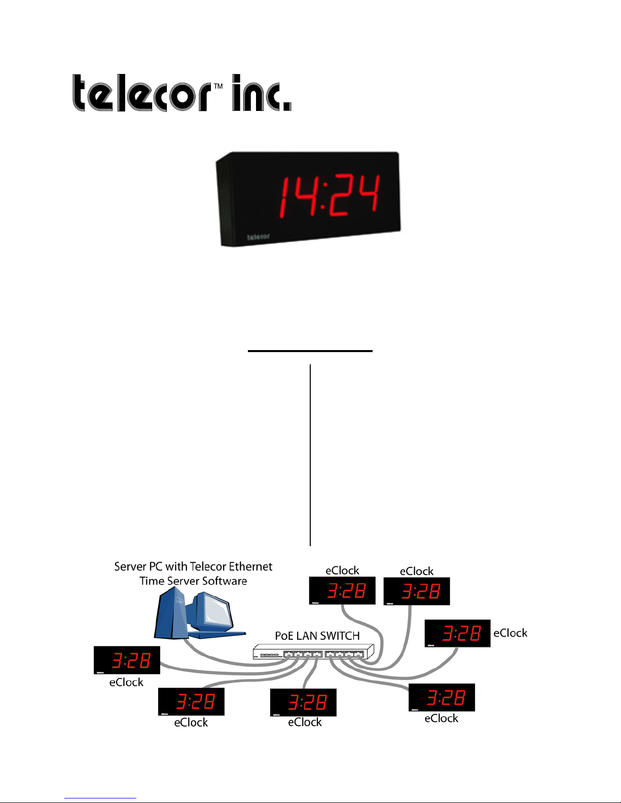
The Telecor Ethernet Time Server Software
must be installed on a computer connected
to the same LAN as the eClocks.
Note: The Telecor Ethernet Time Server
Software is only supported on Microsoft
Windows 7 64-bit Professional,
Enterprise, and Ultimate editions.1
Follow the instructions below to install the
Telecor Ethernet Time Server Software:
1. Use your Internet browser to go to
the MyTelecor website at
http://www.mytelecor.com.
2. At the main menu, click the Web
Store option.
3. From the left column, click on the
eClocks option.
4. From the list of displayed products,
click on the SW-ETS item.
5. At the Time Server Software page,
scroll down to the related documents
section and click on the Telecor
Ethernet Time Server Software
link.
6. The Telecor Ethernet Time Server
Software will have a suffix
indicating its version. E.g., Telecor
Ethernet Time Server Software V1.0
GR1.
7. When prompted by your Internet
browser, save the file to a temporary
folder. E.g., C:\TEMP\
1Telecor tests the installation of its software products on the
U.S. English version of Microsoft operating systems. Other
regional or languages versions of Microsoft operating
systems may not fully support Telecor software.
8. Using Windows Explorer, navigate
to the folder where the file was
downloaded to. Double-click the file
to open the ZIP file. Copy the
contents of the ZIP file to a
temporary folder.
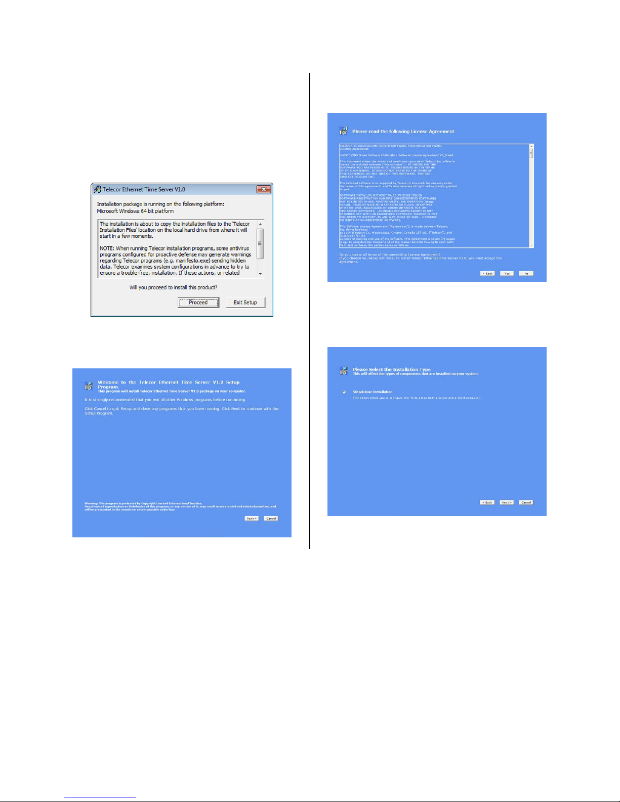
9. Using Windows Explorer, navigate
to the folder where the contents of
the ZIP file were copied to. Double
click on Setup.exe to run the
installation program.
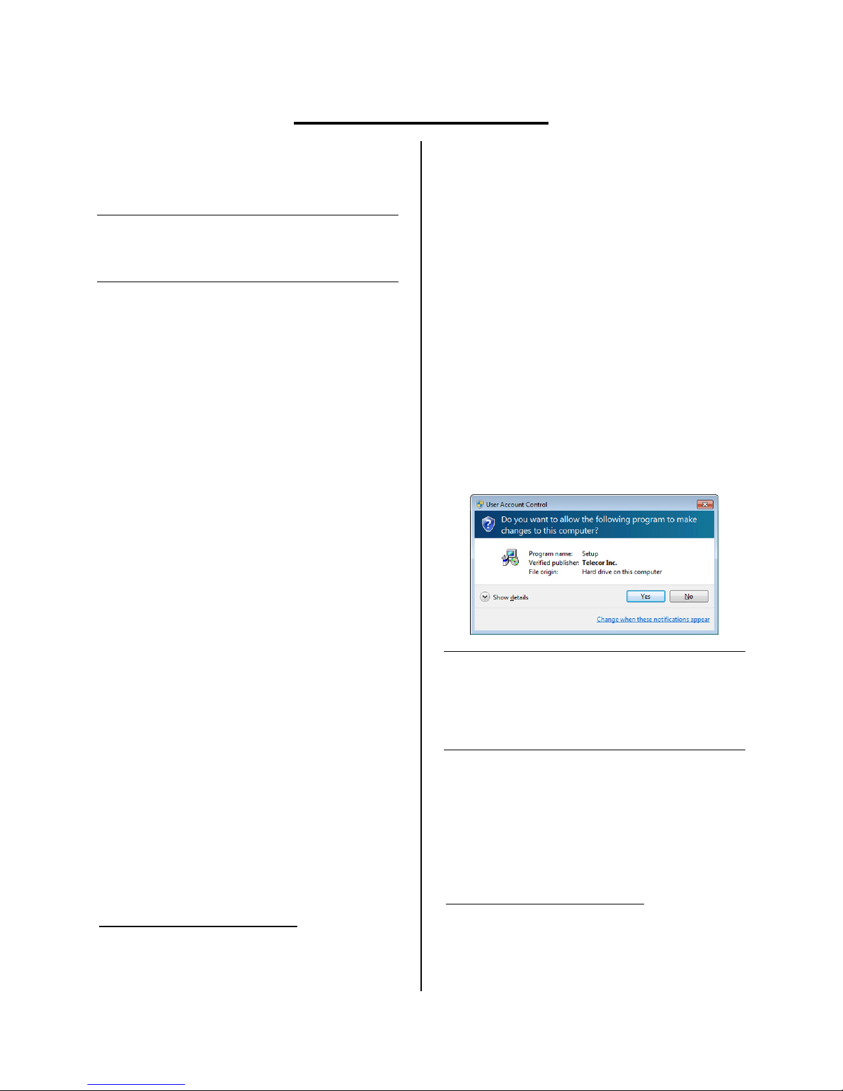
10. You may see a User Account Control
message asking to allow a program
published by Telecor Inc. to make
changes to your computer. Click
Yes.
Note: If the User Account Control message
states that the program publisher is
unknown, you need to update your
computer's certificate store. Go to
https://www.startcom.org using
Microsoft Internet Explorer.2
2Be sure to note the httpsin the URL. Certificates are
automatically updated when the website is visited.
Microsoft Internet Explorer must be used to view the
website. Any other web browser cannot be used to update
the certificate store.