TelePost LP-PAN Product guide

1
LP-PAN
Software Defined
IQ Panadapter
Operating &
Assembly Manual
April 2009
TelePost Incorporated
Rev. D7

2
Table of Contents
Introduction ..............................................................................................................3
Parts List...................................................................................................................4
Assembly..................................................................................................................7
Installation & Setup ...............................................................................................12
Operation................................................................................................................19
Using LP-Pan with CW Skimmer ..........................................................................23
Circuit Description .................................................................................................24
Schematic ..............................................................................................................25
Troubleshooting & Support....................................................................................26
Specifications and Warranty .................................................................................27
Appendix A ............................................................................................................28
Copyright and Trademark Disclosures
LP-PAN is a trademark of TelePost Inc. Windows® is a registered trademark of Microsoft Corporation. Material in this
document copyrighted ©2007,8 TelePost Inc. All rights reserved. LP-Bridge copyrighted ©2007,8 TelePost Inc. All rights
reserved. PowerSDRTM is an open source application for use with IQ based software defined radios, and is a trademark of
FlexRadio Systems.

3
Introduction
Read Carefully Before Continuing.
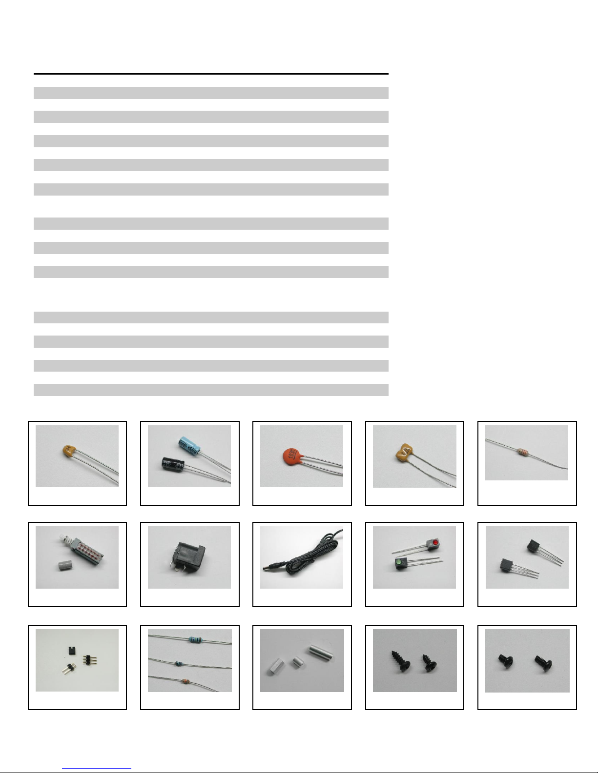
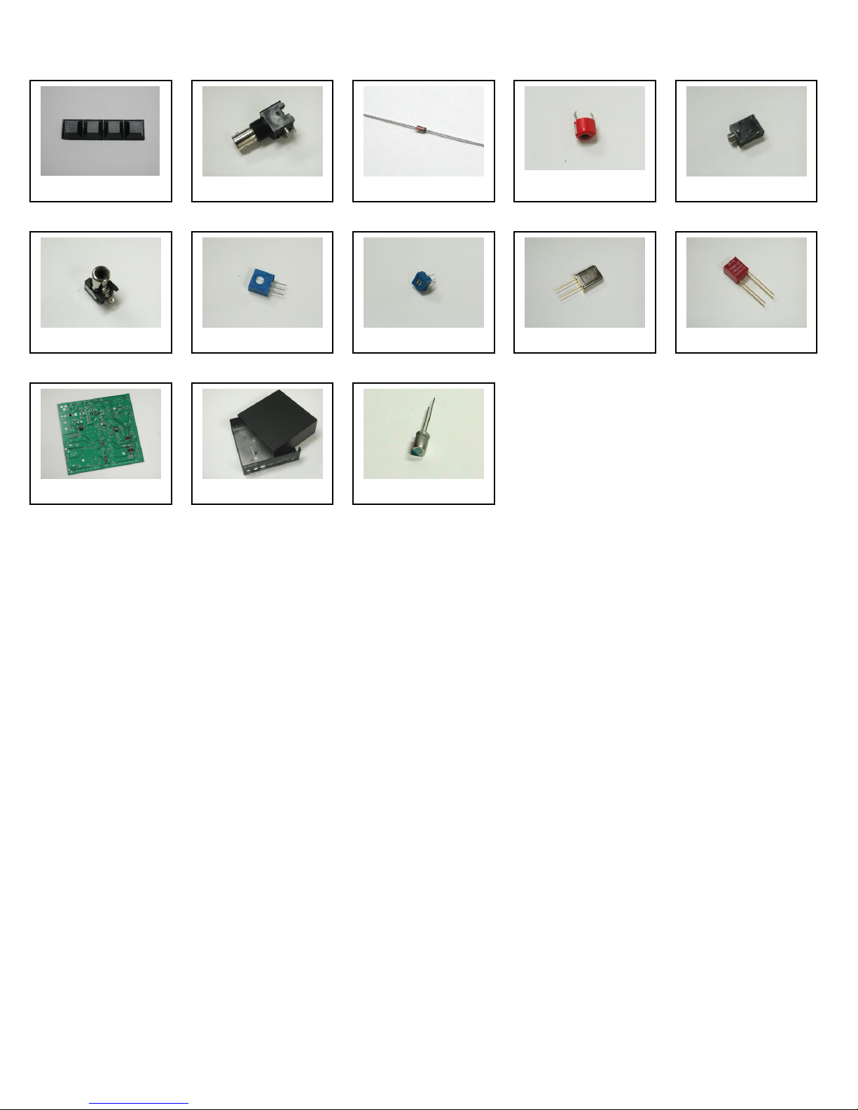
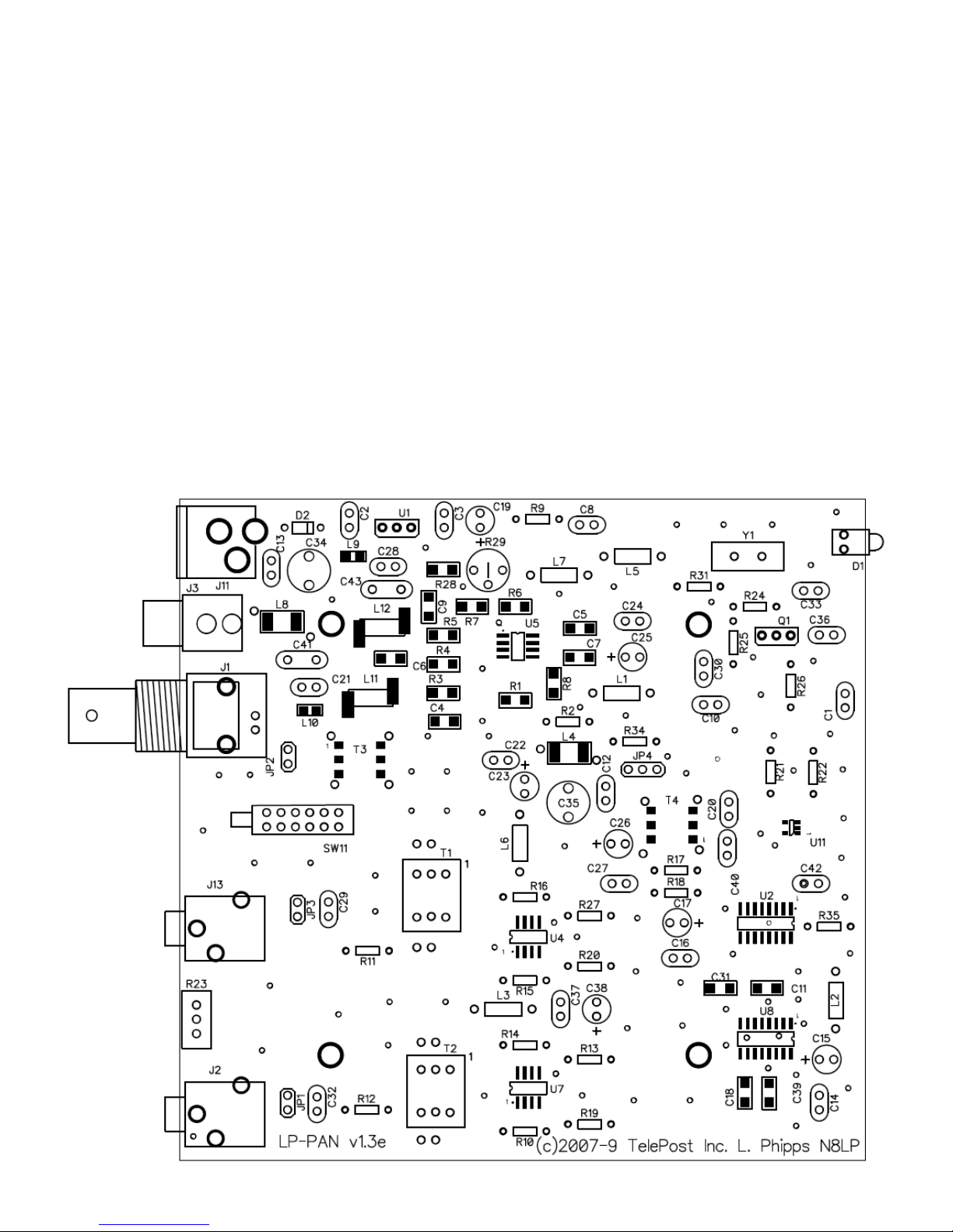
Assembling LP-PAN is a straightforward job, and you should have no trouble if you follow the instructions. Take special note of the
connection diagram, and become familiar with the basics of how the various components fit together in the system.
Installing and configuring PowerSDR can be tricky. It is a complex program, and requires quite a few steps to get set up properly. Lots
of Flex Radio users have done this though, so don’t let it scare you. Pay special attention to the sound card setup. If you’re using the
E-MU 0202 USB sound card, you will probably want to visit the Creative Labs website for the latest driver. The E-MU driver does not
support Windows 2000, but works with XP and VISTA, 32 and 64. There is some question about whether there may be a problem in XP
SP3 though. I believe SP3 post dates the latest E-MU driver, though.
If you get in trouble, help is an email away. There are plenty of helpful users on the LP-PAN User Group,
http://groups.yahoo.com/group/LP-PAN/ , or you can send an email to [email protected]om. Phone support is also available at 734-
455-3716.
LP-PAN Features
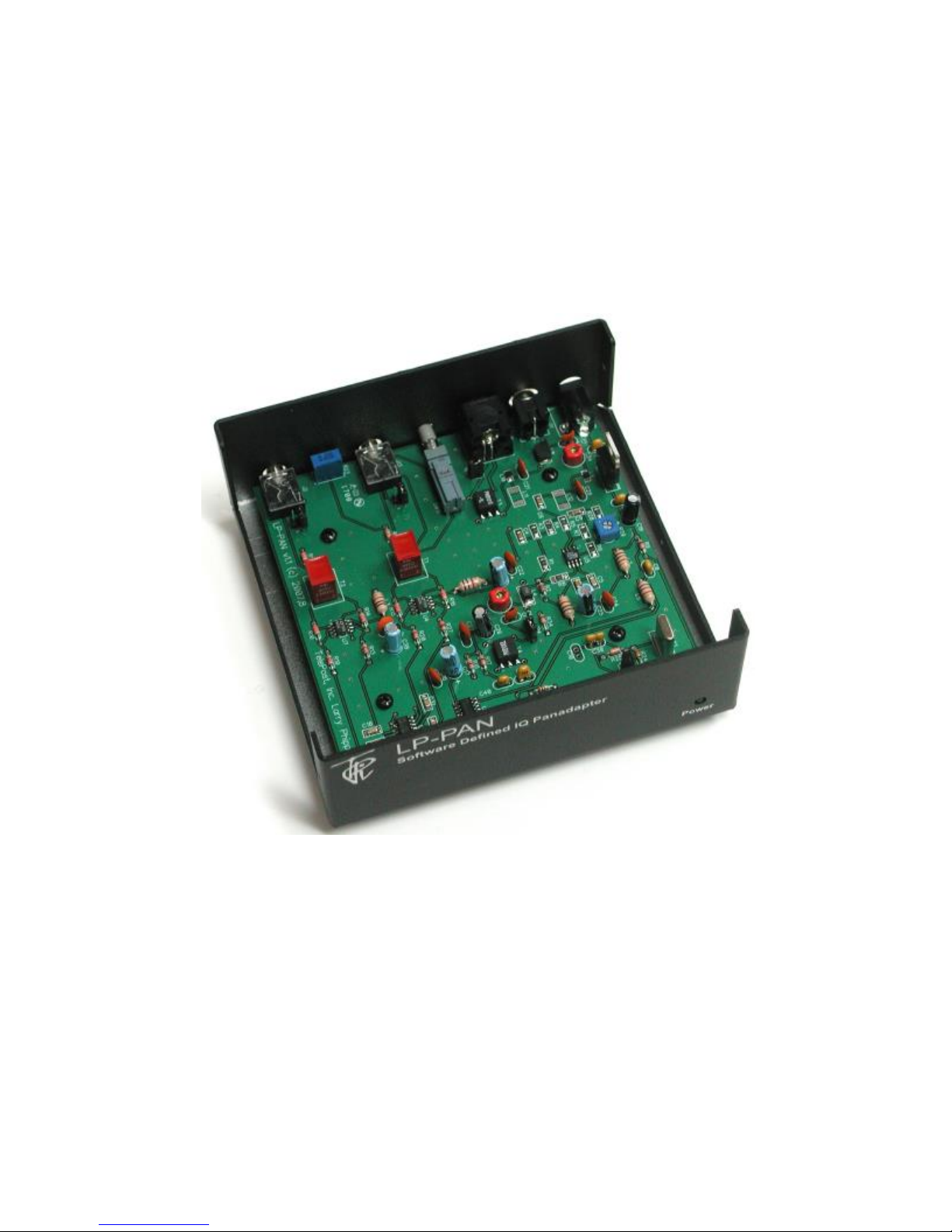
LP-PAN is a software defined IQ direct conversion panadapter. Here is a list of current features...
* Up to 192 kHz display on PC, sound card dependent
* Switching quadrature detector for high dynamic range
* Strong buffer amp with low NF and very high LO isolation.
* Excellent THD and IMD performance
* Ground isolated inputs / outputs with mil spec audio xfmrs
* Low output Z, balanced or unbalanced.
* Fully balanced architecture with balanced and unbalanced outputs
* Jumperable ground lift on RF input and audio outputs
* Works with many SDR programs.
* Adjustable gain to interface almost any sound card
* Point and click frequency control with PowerSDR / IF Stage and LP-Bridge or HRD . In addition, LP-Bridge allows sharing of K3 / LP-
PAN with almost any logger, and even programs such as CW-Skimmer
* Powder coated aluminum enclosure with silk screened graphics.
* Hardware or software mute
* Available for IF frequencies of…
8.215 MHz (Elecraft K3)
8.83 MHz (Kenwood)
9.0 MHz (Orion)
4.915 MHz (Elecraft K2)
10.7 MHz (IC-R8500/9500, others)
Note: Specifications dependent on sound card, and subject to change. Cited values were taken with an E-MU 0202 USB sound card.
All measurements also apply to E-MU 1212m and 1616m PCI cards, and M-Audio Firewire Audiophile 2496 card (limited only by 96
kHz display width). For latest sound card info, see www.telepostinc.com/soundcards.html

4
Parts List - Subject to change without notice. Pictures shown at end of parts list.
Pre-installed SMT parts
Quantity
Designation
Description
5
C5,11,18, 31, 39
0.01uF
2
C4, 6
0.1uF
1
C7
1uF
1
C9
0.22uF
1
L4
10uH
1
L8
12uH
0
L9,10
0.11uH (alternate to L11,12)
2
L11, 12
0.11uH
2
R1, 3
1K 1%
1
R4
4.7K 1%
1
R5
200 ohm 1%
2
R6, 7
499 ohm 1%
2
R8, 28
49.9 ohm 1%
1
T3
Toroid XFMR 1:1
1
T4
Toroid XFMR 4:1
1
U11
ADCMP600 Comparator
1
U2
74HC/HCT163 Counter
2
U4,7
LT6231 Low Noise Op-Amp
1
U5
AD8007 Transconductance Amplifier
1
U8
SN74CBT3253D 4x2 Analog Multiplexer
Through-Hole Parts
Quantity
Designation
Value
1
C1
33pF ceramic disc (marked 33) Fig. 3
6
C2,3,8,20,33,42
0.1uF monolithic (marked 104) Fig. 1
--
C10
Not used
1
C12
18pF ceramic disc (marked 18) Fig. 3
K2: 81pF (marked 81)
1
C13
10pF ceramic disc (marked 10) Fig. 3
K2: 68pF (marked 68)
8
C14,16,22,24,27,29,
32,37
0.01uF ceramic disc (marked 103) Fig. 3
5
C15,17,23,25,38
1uF (25V electrolytic) Fig. 2
1
C19
100uF (25V electrolytic) Fig. 28
2
C21,28
Kenwood: 220pF( 221), 10.7MHz: 0.001uF
(102), K3/K2/Orion: None
1
C26
10uF (25V electrolytic) Fig. 2
1
C30
47pF SM (47) Fig. 4, 10.7MHz: 22pF(22)
2
C34,35
4-20pF trimmer cap Fig. 19
1
C36
56pF ceramic disc (marked 56) Fig. 3
1
C40
0.001uF ceramic disc (102) Fig. 3
2
C41,43
3300pF ceramic disc (332) Fig. 3
Kenwood/Orion: 2700pF(272), K2: 0.01uF(103)
10.7MHz: 0.001uF(102),
1
D1
Green LED Fig. 9
1
D2
1N4148 Fig. 18
1
J1
Insulated BNC connector Fig. 17
2
J2,13
3.5mm Stereo Audio Jack Fig. 20
1
J3
RCA Jack Fig. 21
1
J11
2.5mm DC Power Connector Fig. 7
4
2-pin Jumper Fig. 11
3
JP1-3
2-pin Header Fig. 11
1
JP4
3-pin Header Fig. 11

5
Quantity
designation
Value
6
L1,2,3,5,6,7
1mH RF Choke (br-bk-rd) Fig. 5
1
Q1
MPS5179 transistor Fig. 10
2
R2,31
10 ohm 1/8W res. (br-blk-bk) Fig. 12
4
R9,17,18,34
1K 5% 1/8W res. (br-blk-rd) Fig. 12
4
R10,14,15,16
1.1K 1% 1/8W res. (br-br-bk-br-br) Fig. 12
1
R11
1.5K 5% res. (br-grn-rd) Fig. 12
3
R12,21,22
2K 5% 1/8W res. (rd-bk-rd) Fig. 12
4
R13,19,20,27
22 ohm 1% 1/8W res. (rd-rd-bk-gld-br) Fig. 12
1
R23
1K Pot Fig. 22
2
R24, 35
10K 5% 1/8W res. (br-bk-or) Fig. 12
1
R25
27K 5% 1/8W res. (rd-viol-or) Fig. 12 (1% may
be supplied as alternate)
1
R26
470 ohm 5% 1/8W res. (yel-viol-br) Fig. 12
1
R29
200 ohm Pot Fig. 23
1
SW11
4PDT Pushbutton Switch & Keycap Fig. 6
2
T1,2
Audio Output Xfmr, 600 ohm Fig. 25
1
U1
78L05 5V Regulator Fig. 10
1
Y1
32.836MHz Crystal Fig. 24 (K2: 19.68MHz,
Kenwood: 35.35MHz, TenTec: 36.000MHz,
10.7MHz: 14.31818MHz)
1
PCB Fig. 26
1
Enclosure Fig. 27
1
Power Cord Fig. 8
6
¼” Black Sheet metal screw Fig. 14
8
3/16" Black machine screw Fig. 15
4
1/4" standoff Fig. 13
4
Rubber feet Fig. 16
Fig. 1
Fig. 2
Fig. 3
Fig. 4
Fig. 5
Fig. 7
Fig. 8
Fig. 9
Fig. 10
Fig. 11
Fig. 12
Fig. 13
Fig. 14
Fig. 15
Fig. 6
Parts List –Cont’d

6
Fig. 17
Fig. 19
Fig. 20
Fig. 21
Parts List –Cont’d
Fig. 22
Fig. 23
Fig. 24
Fig. 25
Fig. 26
Fig. 27
Fig. 28
Fig. 18
Fig. 16

7
Assembly
Important warnings –read this before starting assembly
You should visually inspect all the solder pads/traces with a magnifier for any etching problems. This is done before shipping, but I
recommend the builder do a second inspection as well. We do 100% continuity checks of all pads before shipment using computer
controlled flying probes based on PCB netlist coordinates.
All of the SMT components are pre-installed on the main board for your convenience. SMT parts are supplied wherever necessary for
performance or availability reasons. CAUTION: Be very careful handling this board to avoid damage to the installed parts. Anti-static
measures are highly recommended, such as use of an anti-static mat, grounded soldering iron and wrist band.
You may wish to clean the flux from the board after assembly, although it is not necessary with most modern solders. A toothbrush and
alcohol are good for this. Only use rosin core solder. Use of acid core solder voids the warranty. Lead-free solder is OK, and the boards
are RoHS compliant, but it will be more difficult to remove parts without damaging the board should you have to.
Overview
Below is the component placement diagram for the main PCB. These markings match the silk-screening on the PCB, but are repeated
here for clarity. You can also cross out the parts on this graphic as they are installed. You should check all parts before starting to allow
you to start the process of obtaining replacement parts as soon as possible if needed. It is also a good idea to sort the parts in
advance… egg cartons are handy for this (passive parts only). Many crafts stores, Like Michael’s, also have nice plastic cases with
dividers at low prices. If there is any doubt about component values, especially with the 1% resistors which can use strange markings,
check them with your DMM.

8
Assembly Cont’d
Pre-assembly overview.
When assembly starts on page 9, it will roughly follow this order…
Installation of resistors
Installation of ceramic disc capacitors
Installation of miscellaneous small parts
Installation of miscellaneous large parts and connectors
Installation of chokes
The idea is be able to lay the board flat as much as possible during construction, with lowest parts being installed first. The chokes are
the lone exemption… they are installed last so as to make sure each circuit is drawing the right amount of current before continuing.
This is done by monitoring total current draw of LP-PAN while adding the chokes one by one.
You will need the following tools to complete assembly…
Adjustable soldering iron –800 degrees maximum
60/40 alloy solder… .020” (0.51mm) diameter recommended for thermal pads
Needle-nose pliers
Wire cutters
Small Philips head screwdriver
Digital Multimeter
NOTE: The LP-PAN is an intermediate level kit. I would peg the assembly time at about 2-3 hours, plus some reading through the
manual in advance, and some time for calibration afterward. Take your time, and double-check your work, and you should have no
problem. All critical parts are pre-installed.

9
Assembly Cont’d
Step-by-step assembly instructions.
Below is a picture of the assembled PCB. The SMT parts come pre-installed. The component layout diagram on page 7 provides
another aid to component identification. Units after #309 will be ever so slighlty different… mainly in the area of C41 & C43.
It is recommended that you print at least this portion of the manual to allow for easy reference while building, and to allow you to check
off the steps as you complete them. Make sure your work area is static-free to avoid damage to the pre-installed SMT parts. It is also
advisable to wear an anti-static wrist band and grounded soldering iron. Refer to the parts placement graphic on page 7 or the above
picture for questions regarding parts placement.
Install resistors. Solder and clip leads after about six parts are installed to minimize clutter. If you are unsure of the colors used by
some of the manufacturers for the color code, especially the 1% parts, measure the value with a DMM. Occasionally, parts listed
as 5% will be supplied as 1% due to availability when ordering. Double check with DMM.
R2,31 10 ohm 1/8W res. (br-blk-bk)
R9,17,18,34 1K 5% 1/8W res. (br-blk-rd)
R10,14,15,16 1.1K 1% 1/8W res. (br-br-blk-br-br)
R11 1.5K 5% res. (br-grn-rd)
R12 2K 5% 1/8W res. (rd-rd-blk-br-br) or 2.2K 1% (rd-r-bk-br-br)
R13,19,20,27 22 ohm 1% 1/8W res. (rd-rd-bk-gld-br)
R21,22 2K 5% 1/8W res. (rd-bk-rd)
R24,35 10K 5% 1/8W res. (br-bk-or)
R25 27K 5% 1/8W res. (rd-viol-or)
R26 470 ohm 5% 1/8W res. (yel-viol-br)
Install the two audio jacks next. Solder the center lead first, so that you can adjust the jacks to be parallel with the board edge
before soldering the remaining pins.
Install D2. Follow polarity markings on PCB.

10
Assembly Cont’d
Install all 0.1 uF caps (marked 104).
C2
C3
C8
C20
C33
C42
Install all .01 uF caps (marked 103).
C14
C16
C22
C24
C27
C29
C32
C37
Install remaining ceramic disc and SM caps, and the two trimmer caps.
C1 33pF ceramic disc (marked 33)
C12 18pF ceramic disc (marked 18) –For K2: 81pF (marked 81)
C13 10pF ceramic disc (marked 15) –For K2: 68pF (marked 68)
C30 47pF SM (marked 47)
C36 56pF ceramic disc (marked 56)
C40 0.001uF ceramic disc (102)
C34. 35 4-20pF trimmer cap
C21, 28 Not used on K3 or Orion –For Kenwood: 220pF (marked 221), For 10.7: 0.001uF (marked 102)
C41, 43 3300pF ceramic disc (marked 332) –For Kenwood/Orion: 2700pF (marked 272), For K2: 0.01uF, For 10.7:
0.001uF (marked 102)
Install D1 (LED)
Install Q1. Keep leads short.
Install U1. Keep leads short.
Install R29 (pot).
Install SW11
Install J3. You will need to clip off the two plastic tabs on the bottom of the connector off before installing. Latch the rear pin first for
strength, then solder the front pin.
Install J11
Install the three 2-pin and one 3-pin headers. Install a shorting jumper between pins
at JP2. Install a jumper on the ground pin only on JP1 & JP3. Install a jumper
between pins 2 & 3 of JP4 (the two toward the front of the board).
Install T1 and T2. Orient pin 1 near the silk-screened “1” marking, as shown.
Install R23 (pot)
Install crystal, Y1
Install the electrolytics, taking care with polarity. The “+” lead is the longer one, “-“
lead is marked with a black or white stripe, or blue semi-circle.
C15, 17, 23, 25, 38 1uF (25V)
C19 100uF (25V)
C26 10uF (25V)
Install J1

11
Assembly Cont’d
Make sure that your bench is clean and the PCB is not sitting on any cut off component leads. Connect supplied power cable to a
supply of 11-16 VDC. The dashed white lead on the supplied power cable is the + lead (center pin). The green LED should light.
Using your DMM, check for 5.0 VDC (+/- 0.25V) at pin 3 of U1 (the pin connected to C3). Monitor total current draw of LP-PAN
using the DMM or current meter on a power supply. Current draw should be 28mA. Power down.
Install the 1mH ceramic chokes (br-blk-red) one at a time, and check LP-PAN current draw as each one is added to verify no
unexpectedly high changes to total current draw. Expected total current draw is shown after each choke. If your values vary
significantly from these, check your work in the circuit affected by the most recently added choke. Refer to schematic.
L5 29mA
L7 31mA
L1 39mA
L2 41mA
L3 47mA
L6 53mA
Attach the four rubber feet to the bottom of the enclosure.
Install the PCB in enclosure using 3/16” black screws and ¼” standoffs. Loosely install the standoffs on the bottom, and then slide
the board into place, rear first. Attach the screws from the top while aligning the holes on the rear panel, then tighten the screws
underneath.
Install keycap on SW11. The enclosure top will be installed after calibration.
Connections…
Power: 11-16 VDC, center pin +, 2.5mm. The lead with the white stripe on the supplied cable is +. Power can be derived from a wall
wart, accessory power supply, RigRunner type manifold or the accessory power jack on the K3. In general, a supply with a linear
regulator will provide lower overall noise floor and fewer visible spurs on the panadapter display than a switched regulator will.
Mute: Gnd to mute. 5VDC. This will not be used in most installations, a software mute is provided by LP-Bridge / PowerSDR. See
PowerSDR Operation section of this manual for details.
IF Input: From rig. 8.215 MHz for Elecraft K3, 8.83 MHz fo Kenwood, 9.0 MHz for Orion (II).
Bal/Unbal: Out for balanced, In for unbalanced
I/Q Outputs: To sound card inputs
Match: Used to fine tune load balance between channels (Name changed to “Match” starting with serial #101 to better describe its
function).

12
Installation and Setup
System Overview
Before starting, it helps to read this section in order to understand the basics of how the K3, LP-PAN, PowerSDR, Sound Card and LP-
Bridge (or HRD) work together. In general, the duties of each part of the system are as follows:
LP-PAN –Provides audio baseband IQ signals for application to a high quality sound card, which becomes the interface to PowerSDR.
The signals are derived from the broadband IF output of the K3.
PowerSDR –Provides decoding and processing of the audio signals. In addition to providing a panadapter or waterfall display,
PowerSDR is actually a high quality receiver AND sub-receiver. It rivals the K3 in many ways, and adds some features not available on
the K3.
LP-Bridge -Provides a serial interface to the K3, and computer links to PowerSDR. This allows linking of the K3 to PowerSDR for
Frequency, Mode, Preamp setting, Mute, IF Offset and other functions. A serial cable is required between the K3 and the PC to enable
the communication link. Without this link, PowerSDR will act as a panadapter with “relative” frequency display, for instance, +/- 96 kHz
from a center “zero” frequency which represents the center of the IF.
Sound Card –The link between LP-PAN and PowerSDR. A high quality sound card is preferred. These are available for about $80-
$140. See the sound card page on the TelePost website for latest recommendations. http://www.telepostinc.com/soundcards.html

13
Above is a diagram showing typical interconnection of the LP-PAN system.
Installation and Setup cont’d.
Initial LP-PAN Settings
Set JP1 & JP3 to open, JP2 to shorted, and JP4 to pins 2 & 3 (two closest to front of the board), as shown in the photo on page 9. Set
gain pot R29 to the middle of its range, and the Match pot on the rear panel level pot to full clockwise.
Connecting the Sound Card
The connection to the sound card will be largely determined by the sound card inputs. Here are some common possibilities…
Sound card with a pair of unbalanced mono inputs (usable with E-MU 0202, 1616m, M-Audio Audiophile Firewire and 2496).
Set Bal/Unbal switch to Unbalanced (IN). Use a pair of mono cables with the appropriate connectors on the sound card end. In the case
of the E-MU 0202, these will be ¼” phone plugs. Note: The left channel input on the E-MU uses a “funny” combo connector, but accepts
a ¼” mono phone plug. DO NOT use a stereo plug here, as it can get hung up on the ridges around the middle ring.
Sound card with a pair of balanced mono inputs (usable with Delta44, E-MU 1212m, 1616m).
Set Bal/Unbal switch to Bal (OUT). Use a pair of stereo cables with 1/8” male on LP-PAN end and ¼” male connectors on the sound
card end.
Sound card with a single stereo input (typical of inexpensive SoundBlaster type cards).
Set Bal/Unbal switch to Unbal (IN). Use a pair of 1/8” mono cables on the LP-PAN end, and a Y connector or adapter to combine them
into one stereo connector at the sound card end. Generally speaking, a red connector indicates right channel and white indicates left
channel, if marked. If using a commercial Y cable, make sure it is one stereo to two mono connectors, and not just wired in parallel.
In most cases, your monitor speaker will connect to the stereo output jack or headphone jack of the sound card or PC, depending on
setup. You may need a Y adapter for some cards to combine two mono outputs into a stereo monitor output. If you plan to use the sub-
receiver in PowerSDR, stereo speakers are very useful as the two receivers are routed to different channels.
Refer to www.telepostinc.com/souncards.html for specific details about driver settings, pre-configured mixer config files and latest
sound card info. Links to detailed installation instructions for each of the recommended sound cards are provided there.
Connecting the K3 to LP-PAN
Connect the RF input of LP-PAN to the IF output of the K3 using a short, high quality 50 ohm jumper cable with male BNCs on each
end.
The Mute connector can be left unused for now. For a complete discussion of the mute function, see the Operation section of the
manual.
LP-PAN can be powered from a RigRunner type power manifold, a wall wart (11-16VDC at 50mA) or the Accessory DC jack on the
back of the K3. The wire on the supplied power cable with the white line is positive voltage (center pin of DC connector).
Initial Software Installation
Download PowerSDR/IF Stage v0.92 from Scott McClements, WU2X’s web site, http://www.wu2x.com/sdr.html#powersdr Follow the
instructions on his web page for the basic software installation. Setup and preferences will be discussed on the next page of this
manual.
Download LP-Bridge from the TelePost web site at http://www.telepostinc.com/LPB.html Install in the default directory, following the
instructions on the LP-Bridge web page. Refer back here for detailed setup and configuration information.
Note: Both programs are beta versions, and as such are not complete, but should be fully functional at their current level of
development. You should be logged in as Administrator when installing these programs, or using another account with admin privileges.
K3 Firmware: You must be using MCU version 2.13 or later for full compatibility with LP-Bridge. This version added an IF frequency
offset parameter to the CAT protocol which allows automatic frequency correction with LP-Bridge. This feature is not supported in HRD.

14
Installation and Setup cont’d
Special note for European users:
In Windows control panel, open the "Regional and Language Options" panel, select Regional Options, and then Customize. Select "."
(period) for Decimal Point, Select "," (comma) for Digit Grouping Symbol. This is normally reversed in most of Europe. The version of
PowerSDR that we based our sub-version on does not understand European numbering. I think the latest version does, and we will
update to that version this Fall.
If you have a problem with the numerical displays, and have run PowerSDR with normal European numbering already, you will have to
uninstall PowerSDR, including the WU2X folder, because the PowerSDR.mdx can be corrupted. Reinstall after changing the Regional
Options and you should be OK.
Software Installation:
The following assumes that you will be using PowerSDR/IF Stage and LP-Bridge...
Start LP-Bridge. In the section labeled K3 Com Port, select the port that your K3 is connected to. Make sure the K3 is set for 38,400
baud. Warning: If you are using a USB to serial adapter, it is recommended that it use an FTDI chipset. The KUSB adapter sold by
Elecraft does not, and will likely cause problems. Click the Connect button. The button will change to Disconnect unless there’s a
problem. You should see data in the K3 Rcvd Text window in the bottom right of the display, and the K3 Status fields.
Start PowerSDR. After it starts and initializes the FFTs, you may see an error message about HRD not running. Close the message and
select File>Setup and the General tab>Hardware Config sub tab. Select SoftRock IF Stage in the Radio Model section. Make sure
“RFE Present” box is checked. Leave all other settings as they are. Click on the Softrock IF Stage sub tab, and set all the
options to exactly match the above right picture. These will all stay this way except the Global Offset value, which will be fine
tuned later.

15
Installation and Setup cont’d
Go to the Setup>Audio tab>Sound Card sub tab, pictured below. Set the sound card to “Unsupported Card”. Select the correct driver
for your sound card. For most modern professional sound cards, this will be ASIO, but if the card is older you may have to use WDM.
Select your sound card Input and Output, and select None for Mixer. Set the sample rate to the maximum supported by your card, set
Buffer Size to 2048 or 4096 and click Apply. Other settings can be ignored, although I found with my E-MU 0202 card that it wouldn’t
start reliably unless I selected Expert Mode and set Latency to 2ms. Other cards may require a higher setting, up to about 25 ms.
In the Display tab, the vertical scale should be set for a displayed range of -10 to -130 dBm for now (entered range of +10 to –140dBm).
I set Averaging to 200ms, but you may find a different value better. Some users like settings as high as 1000ms. This determines the
averaging when the AVG button is pressed in the main PowerSDR screen, and trades off lower displayed noise for lag when updating
the display. All other settings can be left as they are for now. Click Apply and close the Setup window.
On the main PowerSDR screen, click on the Standby/On button in the upper left and you should hear LP-PAN on your sound card
monitor speaker. Display Mode should be set for "panadapter", and AVG turned on now. To display maximum bandwidth, the PAN
slider should be centered, and the Zoom slider should be all the way to the left. The frequency display should roughly match the VFOA
frequency of the K3. The noise floor with no antenna connected to the K3, K3 preamp OFF, PowerSDR preamp setting set to OFF,
should be between –110 and –120 dBm, and should be flat with no signals, as shown above. We will calibrate the levels later, but the
noise floor should be roughly in the range shown. It depends somewhat on whether you have the K3 buffer mod installed. More on this
in the Calibration section below.

16
Installation and Setup cont’d
If you are using a E-MU 0202 USB card, the input gain controls should be set to between 10 and 12 o’clock to obtain this noise floor.
The two pots should be set as close to exactly the same as you can or else initial image rejection will be poor. If your card uses a
software level control, it should be set near maximum with line input selected, and should indicate the noise floor mentioned above.
Some professional sound cards will have fixed inputs.
If you are seeing any signals (vertical blips), then there is something in your cabling / ground lift settings that is not right. Small blips,
say 10dB above the noise floor could be the result of radiation from your monitor or USB cabling, and rearranging things might help.
Spurious signals and elevated noise levels can also be due to a noisy switching power supply in your shack. I had tiny blips on an older
PC with a 21" CRT monitor, and had to move the sound card away from the monitor. On my laptop and other PC with LCD monitor I
had no problem. Small blips should not be a problem in practice, especially with AVG off.
Connect an antenna, and the noise floor should jump up a bit, depending on band, and you should see lots of signals if the band is
open, as above. I recommend 40m as a good starting point, since there are always signals, and at night you can see some very strong
ones. If all is OK up to this point, continue to the next section.
Calibration
There are only a few hardware adjustments that need to be made in LP-PAN… filter peaking, overall gain setting and load balance.
Note: Filter peaking is only required for kit versions. All adjustments are made while monitoring the PowerSDR display. Load balance is
done in conjunction with the Image Rejection controls in PowerSDR.
Filter adjustment - To adjust the LP-PAN filter, tune to a strong carrier, S9 or better, and peak C35 for maximum strength. If you don’t
have an insulated tuning tool, a small screwdriver can be used, but you will have to remove the screwdriver between adjustments to
see the effect of the adjustment. After C35 is peaked, adjust C34 for maximum signal.
Gain adjustment - To set the gain display accuracy requires a signal source with known output level. This can come from a calibrated
signal generator, or something as simple as the Elecraft XG1 or XG2 test oscillators, which have an output of about –73dBm
(50uV/S9). Set the K3 preamp and attenuator OFF, and the Preamp setting in PowerSDR to OFF. Turn AVG on in PowerSDR. Connect
your generator to the RX ANT input of the K3, and select RX ANT. Adjust your sound card inputs for a displayed level of –73dBm. If you
run out of range on your sound card input, you can adjust R29 on LP-PAN as well. The pot has about 8dB range. If you have an
adjustable generator, you can check sound card gain for proper dynamic range limits. You can decide the range that is ideal for you,
but as a frame of reference I have mine set to clip at –8 dBm input. In my case, I have the K3 buffer mod installed in my K3. This adds
about 10dB gain ahead of LP-PAN. If you don’t have the mod installed, the clip point and noise floor will be about 10dB higher. Details
of the buffer mod can be found in the Files section of the LP-PAN Yahoo Group site at http://groups.yahoo.com/group/LP-PAN/files.

17
Installation and Setup cont’d
Image Rejection Adjustment - At this point, strong signals will display an image on the opposite sideband, with 2nd harmonics at about
70dB down until clipping is imminent. Image rejection is adjusted in the DSP tab in PowerSDR Setup, under the “Image Reject” sub tab,
shown above. If your sound card has hardware input pots, make sure they are set for the same level. If your sound card has software
level controls, set both channels for the same level. Most software mixers have a way of adjusting the levels together. Also, if there is a
balance control, make sure it is centered, or if there are pan controls, make sure the left channel is panned all the way left and the right
panned all the way right. You can set a quick image null by placing the signal midway between the left edge of the display and the
center. The image will appear midway between the center and right edge. AVG should be OFF for these adjustments. Adjust the phase
and gain sliders for minimum amplitude of the image. The sliders provide a rough adjustment. You must use the Up/Dn arrows to fine
tune the null. The adjustment is quite critical to get maximum null depth. The correct setting should be within approx. +/-100.00 for
Phase, and +/- 50.00 for gain. NOTE: If you have an E-MU 0202 sound card, you might want to try this procedure: Set Gain and Phase
sliders for 0.00, set E-MU left channel pot at 11 0’clock, adjust right channel pot for a rough image null. Then use the sliders/arrows to
fine tune. The extra step may be needed in case the physical pot positions on the E-MU are a little out of alignment. Any future
adjustment in the left pot setting will require a readjustment of the right pot and readjustment of the sliders/arrows.
This will not be the best setting for overall broadband image rejection, however. There is an iterative process for improving the
broadband image rejection, which essentially finds a median setting which will be close for all frequencies, but not perfect at any one
frequency.
The procedure is outlined below.
1) Tune in a strong signal (-50dBm or higher) from a signal generator or nearby transmitter.
2) Tune the K3 to put the image midway between the center of the display and the left end of the display.
3) Set the Image Reject Phase and Gain adjustments for minimum image response. Log the values.
4) Retune the K3 to put the image signal midway between the center and the right end of the display. Adjust for minimum response
and log the values.
5) Set the Image Reject controls for the midpoint of the logged settings.
6) Adjust the Match control on the rear panel of LP-PAN for minimum response
7) Retune the image to the original center/left point. Readjust the gain setting in PowerSDR for minimum image. Log the value.
8) Retune the image to the center/right point and readjust the gain setting for minimum image. Log the value.
9) Adjust the gain setting for midway between the two values if they are not the same.
10) If the gain settings logged in steps 7 & 8 are not very close (within 2.0), then you can repeat steps 6-9 to get closer.
When finished, image rejection should remain at 60dB or more over most of the range as you tune, with maybe a bit lower at the edges
and very near the center, depending on sound card. Results will be better with 96 kHz cards because of the smaller bandwidth. Scott
also plans to add auto image nulling in PowerSDR along the lines of what is done in the Rocky program. This would provide an image
rejection of close to 100dB with no adjustments.
You should now be ready to attach the enclosure top, and continue with the remaining software adjustments.
Global Offset adjustment –LP-Bridge provides an offset value to PowerSDR which keeps the IF center frequency of PowerSDR
synchronized with the K3. Due to slight differences in the reference oscillator in the K3 and the local oscillator of LP-PAN, you must
make a small adjustment to bring the two into exact zero beat. The error will generally be within +/-100 Hz of nominal to start with.
Starting with serial # 208, the nominal offset will be 6000, which includes an intentional 6 kHz offset. This was done to move the center
of the passband slightly to avoid problems with some older or cheaper sound cards which have difficulty near an audio frequency of 0
Hz. On earlier models without the additional offset, the nominal value will be 0.

18
Installation and Setup cont’d
To fine tune the Global Offset, tune in a carrier to a comfortable pitch on the K3. Turn the volume of the sound card monitor up so that
you hear the output of PowerSDR at about the same level as the K3. The two tones should be similar, but probably not exactly the
same pitch. Adjust the Global Offset control in PowerSDR until the beat note between the K3 and PowerSDR is 1Hz or less. This
setting will work for all modes.
CW Pitch adjustment –Another adjustment that must be made is for CW Pitch. There are three adjustments that affect pitch, in addition
to the Global Offset adjustment that you just performed. One is in the K3, one is in PowerSDR and the last is in LP-Bridge. Briefly, they
should all be set to the same value. The CW Pitch adjustment in PowerSDR appears on the main display whenever a CW mode is
selected. It is in the section called “Mode Specific Controls”, under the panadapter window.
As soon as Elecraft adds the promised CW Pitch command in the K3, this adjustment will be automated.

19
Operation
LP-Bridge Operation
Normal View
Menu Bar... Along the top of the window. There are three pulldown
menus.
File: Only has one choice, "Exit". You can also exit cleanly by using the
X in the upper right of the LP-Bridge window. Your curent settings are
saved on exiting.
Setup: Can be set for "Show" or "Hide". Normally, it is left on Hide unless
you want to change a setting or run diagnostics on a port.
Help: "Web Help" will display a link to this page. "About" displays version
and copyright data for LP-Bridge.
K3 Port... This is the area where you select the port that your rig is
connected to. The K3 must be set for a baud rate of 38,400, which is the
maximum connection speed for the rig. Warning: If you are using a USB
to serial adapter, it is recommended that it use an FTDI chipset. The KUSB adapter sold by Elecraft does not, and will likely cause
problems.
Click on "Connect" to connect to the K3, and "Disconnect" to disconnect. If you have a virtual port open when you try to disconnect, you
will get an error message to close the virtual port first. If there is a problem connecting to the rig, you will also get an error message.
Check cabling and K3 settings if this occurs. If connection is successful, the row of boxes grouped under the "K3 Status" heading will fill
with data. This is mostly the data that is linked to PowerSDR, but can also be used to verify proper connection to the K3. The current
firmware versions loaded into your K3 are also shown. The "Auto Connect" checkbox is grayed out for now, but will eventually allow LP-
Bridge to automatically connect to the K3 when the program starts.
Virtual Port 1-3... This is the area where you select the ports that LP-Bridge will provide for connecting various applications to the K3.
Ports can be any port that is not already used on your system. When selecting a port to use, you must avoid all real and virtual ports
which already exist, such as those used by USB adapters, devices such as microHam, etc. Select a port number and click Connect. If
the connection is succesful, the button name will change to "Disconnect". If not, you will get an error message. If there is no connection
to the K3, you will also get an error message to connect to the K3 first.
Applications which will connect to this port must be set for the selected port number (not the K3 physical port number). Additional
settings should be 38,400 baud, 8-bits, no parity and 1 stop bit (38400,8,N,1). If the application has a polling rate, it should be set fairly
fast. I use 200ms for most of mine, but if you have an older computer and it bogs down at that setting, a slower one can be used.
Loggers which require minimal data can be set as low as 1 second. Programs which require interactive tuning, or have an S-Meter
display should be to a fast setting.
Handshaking should be set how you would normally for connecting to the K3, ie. if you are using DTR or RTS for PTT or CW keying,
you would leave these settings as they would be if connected to a K3. Keying signals from multiple applications will all key the K3 in
parallel. It is assumed that only one keying application would be in control at any time.
Once again, "Auto Connect" is currently grayed out. There is also a choice for each virtual port to accept "AI1" (Auto Information) from
the K3. VPort1 also allows using "AI2" for applications that require it. Some applications don't poll for data, so the K3 has to initiate the
comms dialog using one of the Auto Information modes. Checking this setting provides a way for them to do that. If in your testing you
find your application does not update when tuning the K3, try checking either "AI1" or "AI2". In my testing, I found that Logic8 requires
"AI1", and N4PY's Pegasus requires "AI2". TRX-Manager can be set up to use polling or "AI2". Other programs I have tried that don't
need these settings include CW Skimmer, DXLabs' Suite, N1MM, MixW, Logger32, Wintest, DX4WIN and HRD.
In addition, there is a little text box for each virtual port which will allow you to type a program name to help you remember which
application is connected to that port. LP-Bridge will remember these titles.

20
Operation cont’d
LP-Bridge Operation
Setup View
Terminal Windows... These let you view traffic to and from the K3 for the serial
port, and to and from applications for the virtual ports. Each window shows the
last 100 comm events, and can help you track down a problem. For instance, if
an application is not polling for a certain command, or you want to verfiy that it
is getting a response that is not being properly displayed. To scroll through the
data, you must disconnect or stop the application from polling, at which point
you can scroll through the lines and look for your problem.
Setup... This area provides a place to choose your settings. These include...
Preamp, Attenuator and CAL: Allow you to set the panadapter vertical scale
offsets so that the displayed levels are correct whether the K3 preamp or
attenuator are on or off. Not implemented yet.
On Top: Allows you to set LP-Bridge to display on top of other applications at
all times.
Polling: Sets the polling rate for LP-Bridge. This largely determines the tuning
"feel", and S-Meter update speed for programs which need this. The default is
200ms.
CW Pitch: This is a temporary control which provides a workaround to a bug.
Once this bug is fixed, the control will disappear. Enter your CW Pitch to match
the setting on the K3 and PowerSDR. The LP-Bridge default is 600 Hz.
DDE Diagnostics... This allows testing of the link to PowerSDR. The K3 must
be disconnected to use these. If the link is working properly, you can select
modes, enter frequencies (in Hz, ie. 14150000), etc. to verify that PowerSDR
follows your commands. PowerSDR should respond with return data in the
DDE Rcvd Text window.
Again, once you have set the settings, you can hide the setup portion of LP-
Bridge.
Table of contents