TeleSite QuickSilver DV202S User manual

TeleSite Part No.
T8009-8001-00-00 Rev 101
TX001-00-00
DV202S Video Transmitter
TeleSite USA Inc. does not warrant that the functions contained in this equipment will meet your requirements or
that the operation will be entirely error free or perform precisely as described in the documentation. This system
has not been designed to be used in life-critical situations and must not be used for this purpose.
Product specifications subject to change without notice.
TeleSite and QuickSilver are trademarks of TeleSite USA Inc.
NOVA and its logo are registered trademarks of Vicon Industries Inc.
Windows is a registered trademark of Microsoft.
TeleSite USA, INC., 225 County Road, Tenafly, New Jersey 07670
TELEPHONE: 201-568-5050 FACSIMILE: 201-568-6444
TOLL FREE: 800-808-5780

FCC Notice
Note: Complies with Federal Communications Commission Rules & Regulations Part 15, Subpart B for a
Class A digital device.
WARNING
This equipment generates and uses radio frequency energy and if not installed and used properly, that is, in
strict accordance with the manufacturer’s instruction, may cause interference to radio and television reception.
It has been type tested and found to comply with the limits for a Class A computing device in accordance with
the specification in subpart B of part 15 of the FCC rules, which are designed to provide reasonable protection
against such interference in a commercial installation. However, there is no guarantee that interference will not
occur in a particular installation. If this equipment does cause interference to radio and television reception,
which can be determined by turning equipment off and on, the user is encouraged to try and correct the
interference by one or more of the following measures:
•Reorient the receiving antenna.
•Relocate the equipment with respect to the receiver.
•Relocate the equipment away from the receiver.
•Plug the equipment into a different electrical outlet so that the equipment and receiver
are on different branch circuits.
If necessary, the user should consult the dealer or an experienced radio/television technician for additional
suggestions.
The user may find the following booklet prepared by the Federal Communications Commission helpful:
“Interference Handbook, Bulletin CIB-2”
This booklet is available from the U.S. Government Printing Office, Superintendent of Documents, Mailstop
SSOP, Washington, D.C. 20402-9328, ISBN 0-16-045542-1.
WARNING: Power must be removed from this unit before removing circuit modules or Ribbon Cables.
CAUTION: This unit contains circuit cards with integrated circuit devices that can be damaged by static
discharge. Take all necessary precautions to prevent static discharge.


TX001-00-00 Rev 101 QuickSilver DV202S Video Transmitter Contents •
••
•i
Contents
INTRODUCTION.................................................................................................................. 1
How to Use this Manual ................................................................................................................................ 1
For experienced installers:........................................................................................................................ 1
For novice installers:................................................................................................................................. 1
Unpacking and Inspection............................................................................................................................ 1
INSTALLATION ...................................................................................................................4
Quick Installation........................................................................................................................................... 4
DV202S Transmitter/X-566 Modem ......................................................................................................... 4
CRU.......................................................................................................................................................... 5
I-MODEM Modem..................................................................................................................................... 7
Detailed Installation....................................................................................................................................... 9
DV202S Transmitter/X-566 Modem ......................................................................................................... 9
DV202S Transmitter Directly Connected to Receiver............................................................................. 13
CRU........................................................................................................................................................ 15
AUDIO BD Internal Audio Card .............................................................................................................. 19
32 MEM Transmitter Memory................................................................................................................. 19
CONFIGURATION ............................................................................................................. 20
Using Alarm Inputs...................................................................................................................................... 20
Transmitter.............................................................................................................................................. 20
CM-4 Module .......................................................................................................................................... 21
Using Relay Outputs.................................................................................................................................... 22
Transmitter.............................................................................................................................................. 22
RM-16 Module ........................................................................................................................................ 23
Using Audio.................................................................................................................................................. 24
Basic Audio Using Relays....................................................................................................................... 24
OPERATION...................................................................................................................... 25
Resetting the Transmitter ........................................................................................................................... 25
TROUBLESHOOTING....................................................................................................... 26
Transmitter ................................................................................................................................................... 26
CRU ............................................................................................................................................................... 26
Receiver........................................................................................................................................................ 26
Modem .......................................................................................................................................................... 26
Alarms........................................................................................................................................................... 26

ii •
••
•Contents TX001-00-00 Rev 101 QuickSilver DV202S Video Transmitter
Relays............................................................................................................................................................26
Audio..............................................................................................................................................................26
SHIPPING INSTRUCTIONS...............................................................................................27
REFERENCE......................................................................................................................28
TECHNICAL INFORMATION.............................................................................................29

TX001-00-00 Rev 101 QuickSilver DV202S Video Transmitter Important Safeguards •
••
•iii
Important
Safeguards
GRAPHIC SYMBOL EXPLANATION
The lightening bolt symbol alerts the user to the presence of
dangerous voltage that may present the risk of electric shock.
The exclamation point symbol alerts the user to the presence of
important operating and maintenance instructions.
1. Read Instructions - Read all safety and operating instructions
before the product is operated.
2. Retain Instructions - Retain all safety and operating
instructions for future reference.
3. Heed Warnings - Pay attention to all product warnings.
4. Follow Instructions - Follow all operating instructions.
5. Cleaning -(Do not use caustic, abrasive or aerosol cleaners)
a) For units that CAN BE DISCONNECTED from the power
source, use a damp cloth for cleaning.
b) For units that CANNOT BE DISCONNECTED from the power
source, use a damp cloth for cleaning and do not allow
moisture or liquids to enter vents.
6. Attachments - Use only TeleSite recommended attachments to
prevent unit damage and personal injury.
7. Water and Moisture - Use only products designed for outdoor
environments where they will be exposed to water or moisture.
8. Accessories - Do not place the unit on an unstable surface to
avoid falling. Use only TeleSite recommended mounting accessories..
9. Ventilation - Do not block ventilating slots and openings as they
ensure reliable operation. Do not place the unit near a heat source
or into an enclosure unless recommended by TeleSite.
10. Power Sources - The product should only be operated from
the recommended power source. If not specified, consult your
TeleSite dealer or local power company.
11. Grounding - Only products equipped with a 3-prong grounded
plug should be inserted into a grounded power outlet. Contact an
electrician to replace an obsolete outlet. Do not force a plug into a
non-grounded outlet.
12. Power Cord Protection - Power supply cords should not be
routed in trafficked areas or in tight spaces where they will be
pinched or used to bear weight. Allow some slack in the cord
where it enters the unit.
13. Outdoor Cable Grounding - Use only grounded outdoor
cables to protect against voltage surges and static charges.
Section 810 of the National Electrical Code, ANSI/NFPA 70-1984,
provides information on proper grounding of the lead-in wire to an
antenna discharge unit, size of grounding conductors and the
requirements of grounding electrodes.
14. Lightning - Disconnect the product from its power source and
cable system when possible to prevent damage due to lightning
and power-line surges.
15. Power Lines - Do not locate outside cables over power or
utility lines where they can fall and make direct contact. Contact
with power lines can be fatal.
16. Overloading - Do not overload wall outlets and extension
cords to prevent risk of fire and electric shock.
17. Object and Liquid Entry - Never probe through, or spill liquid
into, enclosure openings to prevent risk of fire or electric shock.
18. Servicing - Refer all servicing to qualified service personnel.
19. Damage Requiring Service - Obtain service when:
a) The power-supply cord or plug is damaged.
b) Objects have fallen or liquid has been spilled into the product.
c) The product is not designed for outdoor use and has been
exposed to water or moisture.
d) The product does not operate per the operating instructions.
Perform TeleSite recommended adjustments, modifications
and troubleshooting only to avoid unit damage and personal
injury.
e) The product has been dropped.
f) The product shows a significant change in performance.
20. Replacement Parts - Use only TeleSite specified replacement
parts or an approved equivalent to prevent unit damage and injury.
21. Safety Check - Request safety checks to be performed
following repair or maintenance to verify proper operation.
22. ESD Precaution - Take all normal electrostatic discharge
precautions to avoid component damage during installation and
operation.
23. For 230 VAC Devices- When the disconnect device is not
incorporated in the equipment or when the plug on the power
supply is intended to serve as the disconnect device, follow the
guidelines below:
a) For permanently connected 230 VAC units, a readily
accessible disconnect device must be incorporated into the
site wiring.
b) For 230 VAC units with a plug, the outlet must be installed
near the unit and be easily accessible.


TX001-00-00 Rev 101 QuickSilver DV202S Video Transmitter Introduction •
••
•1
Introduction
The information in this manual covers the installation, configuration and operation of the TeleSite USA
QuickSilver Global Video Transmission System. This system should only be installed by a qualified technician
using common hand tools and approved materials in accordance with national, state and local wiring codes.
How to Use this Manual
This manual was designed to provide the best overall instructions for the installation and operation of the
Telesite USA QuickSilver Global Video Transmission System. The graphics and terminology used in this
manual have been carefully selected to enable a clear and distinct understanding of QuickSilver and its
components. This manual has been formatted to present distinct methods of installation for experienced and
novice installers.
For experienced installers:
Start at the Quick Installation sub-section of the Installation section to use the simplest steps for proficient
installers. Follow the references provided in the text for items such as wiring tables and DIP Switch settings.
Refer to the subsequent sections of Installation, Configuration and Operation for detailed descriptions of any
method.
For novice installers:
Complete the remainder of this section (Introduction) and proceed to the Detailed Installation sub-section of
the Installation section to use the most explicit steps for beginning installers. When complete, proceed to the
Configuration and Operation sections to continue the total installation.
Unpacking and Inspection
All Telesite USA equipment is tested and inspected before leaving the factory. It is the carrier’s responsibility
to provide suitable delivery. Inspect the cartons upon delivery and, if damage is present, make detailed notes
on the carrier’s bill. Then, obtain the carrier agent’s signature and file a damage claim as soon as possible.
Open the cartons and inspect the equipment for damage. Save the cartons and packing material. If damage is
present, contact the carrier and file a damage claim immediately. If the equipment must be returned to Vicon
for repair, follow the instructions in the Shipping Information section of this manual.
The DV-202S Transmitter and CRU units are neatly packaged in compact enclosures that can be surface
mounted or shelved inside a standard rack panel. The optional add-on boards are high quality, modular, and
designed for easy installation.
The DV-202S complies with FCC Class A computing device requirements and complies with European
Community EMC Directive 89/336. The product was subjected to the testing outlined in European
Normalization Standard EN 50081-1 (Electromagnetic Compatibility-General Emissions Standard Part 1:
Residential, Commercial and Light Industry), and EN 50082-1 (Electromagnetic Compatibility-General
Immunity Standard Part 1: Residential, Commercial, and Light Industry).
TeleSite USA strongly recommends the use of line conditioners, voltage regulators, and uninterruptible power
supply (UPS) systems. For software configuration and operation, refer to the QuickSilver Global Video
Transmission System Software Manual TX001-10.
Note: Read all instructions before beginning any installation.
Note: The following instructions are “typical.” It may be necessary to deviate from them for any particular
installation.
2 •
••
•Introduction TX001-00-00 Rev 101 QuickSilver DV202S Video Transmitter
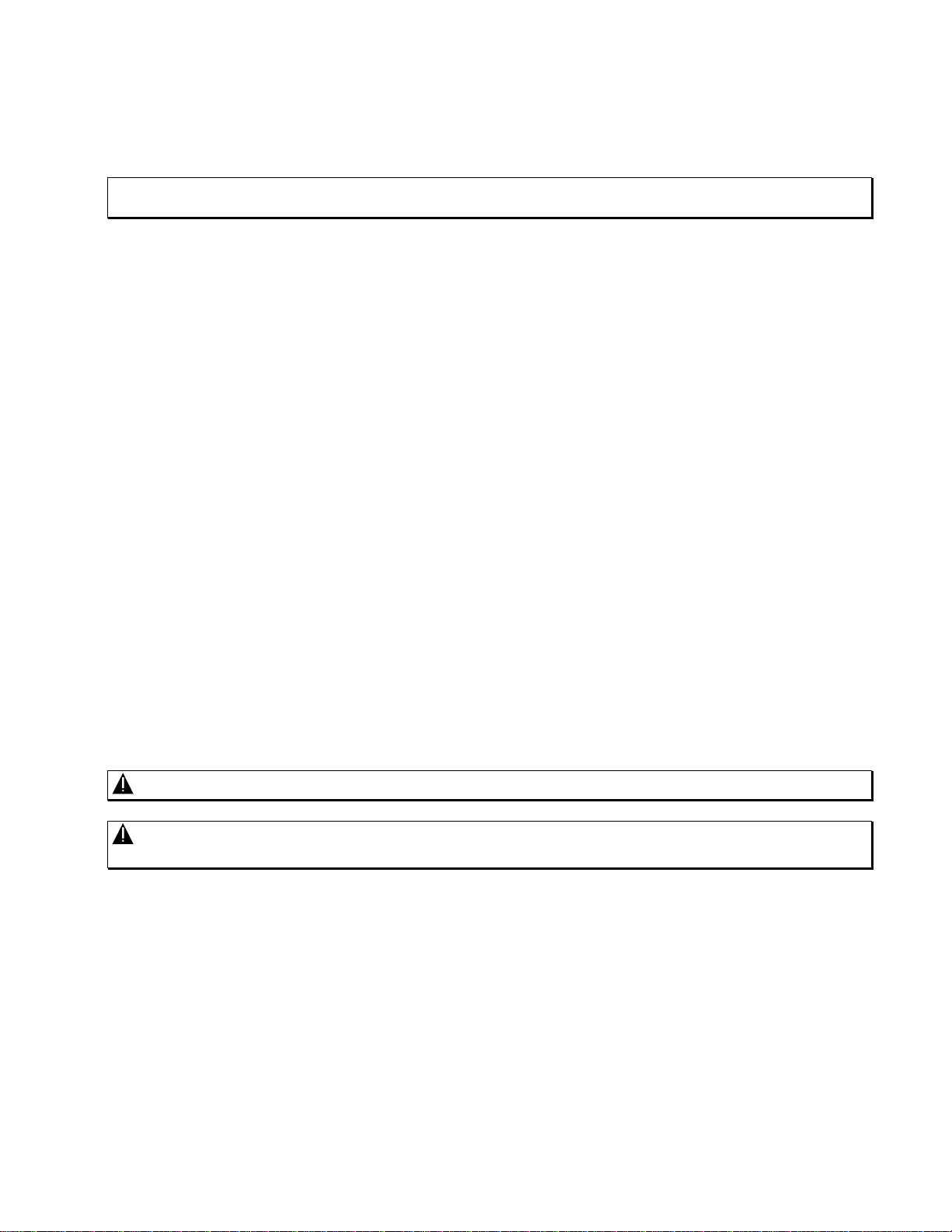
The QuickSilver system offers a solution for remote video control and monitoring requirements. Composite
video, audio (optional), and control signals are transmitted over ordinary telephone lines (PSTN, ISDN and
cellular type) as shown in Figure 1. Software information can be found in TeleSite Manual TX001-10.
The core system is comprised of the DV202S Transmitter, QS Receiver Software, a PC-type computer and a
pair of Modems. The Transmitter and a Modem are installed and configured at the remote site. The Receiver
software and remaining Modem are installed into the computer at the local site. Each remote site can then be
accessed by the local site to begin receiving video. The software provides complete configuration, operation
and monitoring of the remote-site devices.
Figure 1
Basic QuickSilver System
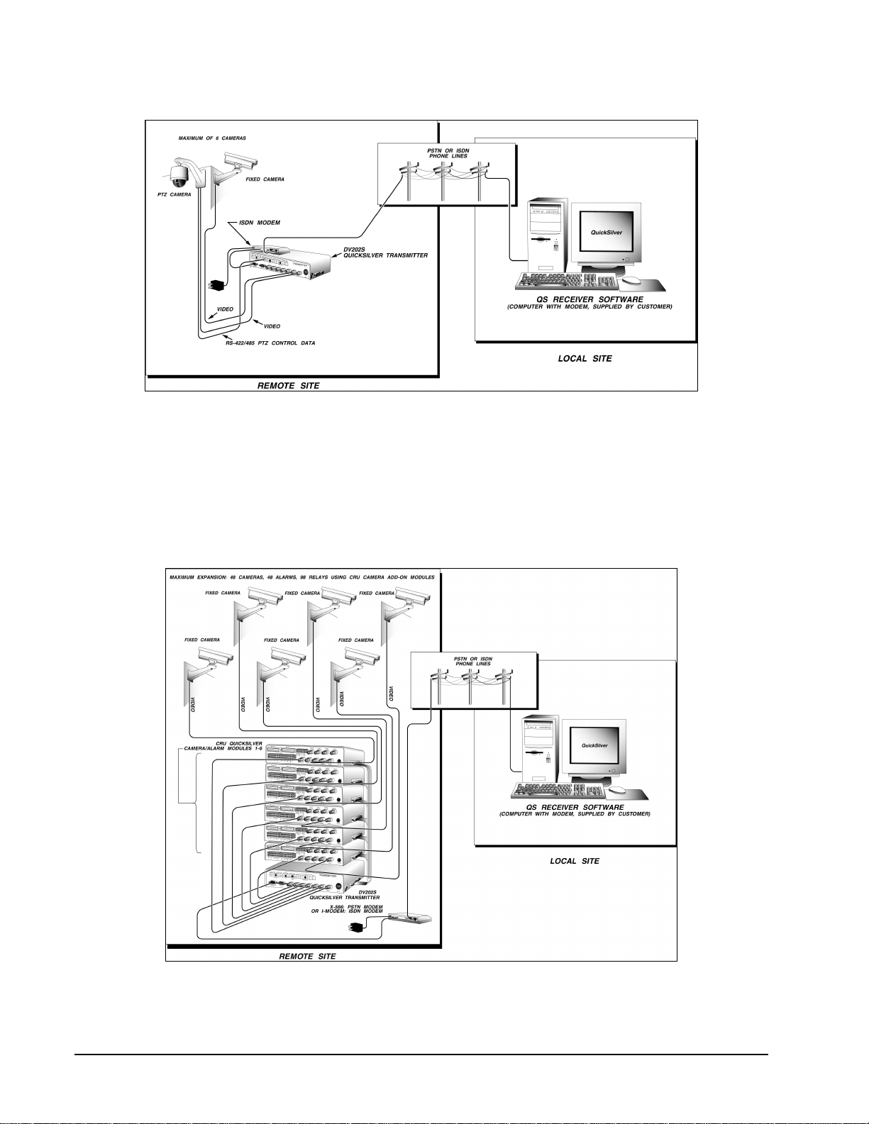
Figure 2
Ex
p
anded QuickSilver S
y
stem
TX001-00-00 Rev 101 QuickSilver DV202S Video Transmitter Introduction •
••
•3
The Transmitter can
be expanded to handle
additional cameras,
relays and alarms
using a CRU. A
Transmitter can be
outfitted to support up
to 6 CRUs. Each basic
CRU has 4 camera
inputs and 4 alarm
inputs. A CRU can be
equipped with a CM-4
Camera option board
and a RM-16-relay
Expansion Card to
increase its capability
to 8 camera inputs, 8
alarm inputs and 16
relay outputs.
With 6 fully equipped
CRUs connected in
tandem, the total
system can support 48
cameras, 48 alarm
inputs and 98 relays.
Refer to Figure 2.
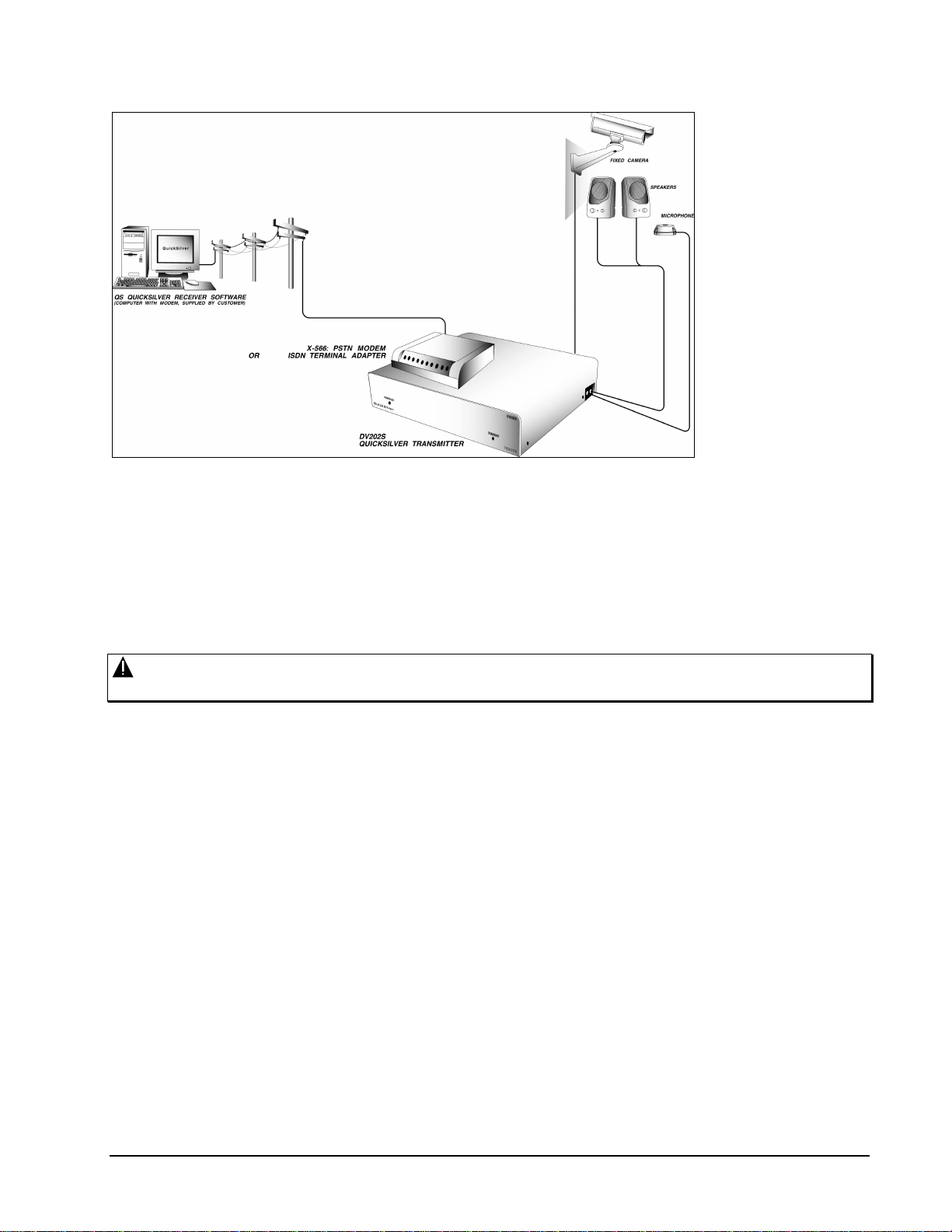
The system also
supports simplex
(listen) and duplex (simultaneous talk/listen) audio when the Transmitter is equipped with the optional AUDIO
BD Internal Audio Card, Microphone and Speakers. See Figure 3 for a basic system audio diagram.
Warning: Audio is designed to provide two-way communication and should not be used as a covert
listening tool.
In addition, the Transmitter is capable of providing multi-channel audio using optional Louroe Electronics
hardware.
The system also supports connection to an several manufactured Camera Domes via an RS-232 or RS-
422/485 connection. Refer to document TX006, Pan, Tilt and Zoom setup instructions for details on how to
connect these.
Figure 3
Basic Audio Setup
4 •
••
•Installation TX001-00-00 Rev 101 QuickSilver DV202S Video Transmitter
Installation
The installation of QuickSilver is a multi-step process. This section will detail the installation of QuickSilver
using a Quick Installation or Detailed Installation sub-section. Both sub-sections detail the installation of the
Transmitter with the PSTN (X-566) modem. Since several types of modems can be used, refer to the later
subsections referring to the ISDN (I-MODEM) when using an ISDN type modem.
Installation can be summarized with the following steps:
1. Unpack the components and prepare the remote site for hardware installation.
2. Install, wire and configure all components at the remote site.
3. Verify the power-on condition of all components at the remote site.
4. Install and configure the software on the Receiver at the local site.
5. Proceed to the Operation section and verify proper connection and installation to the remote site.
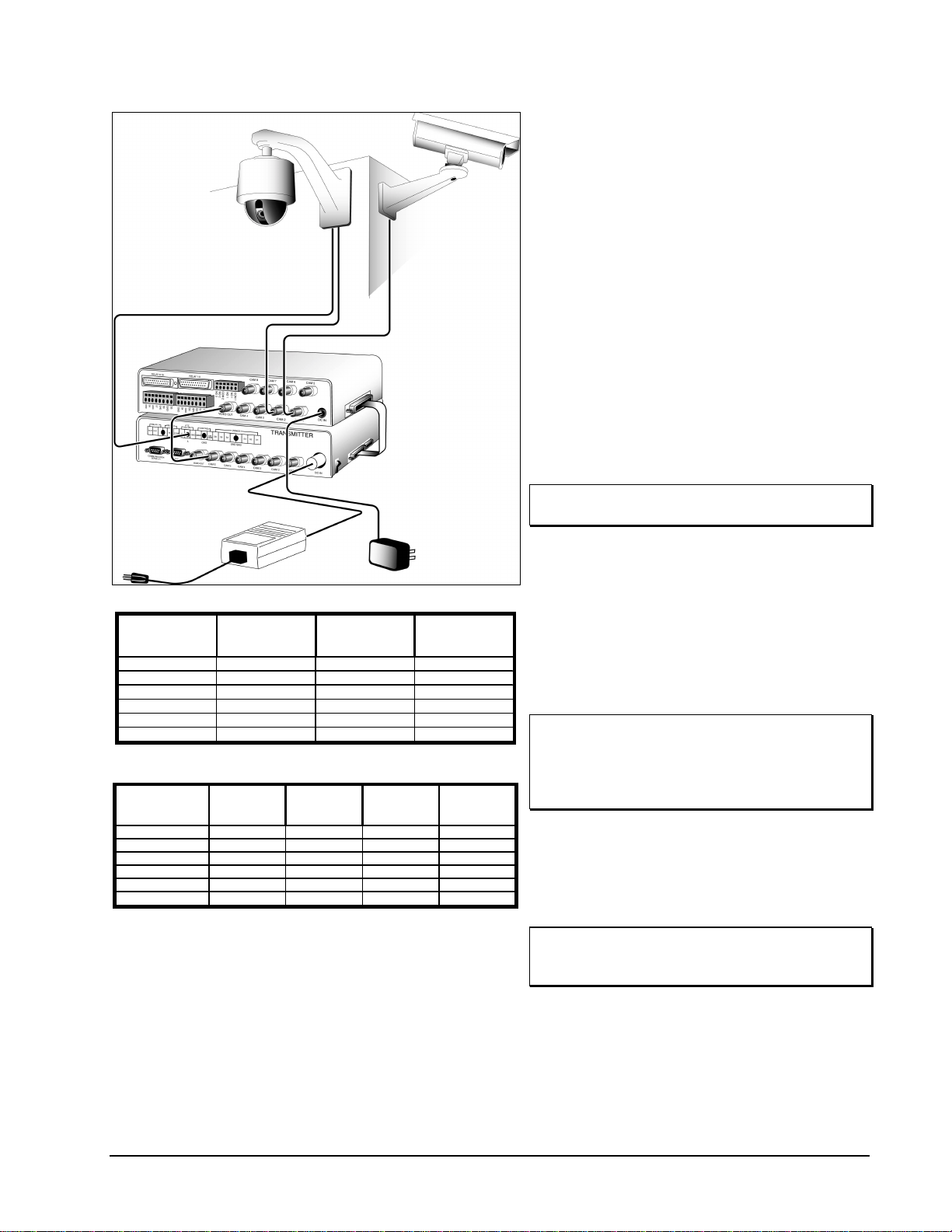
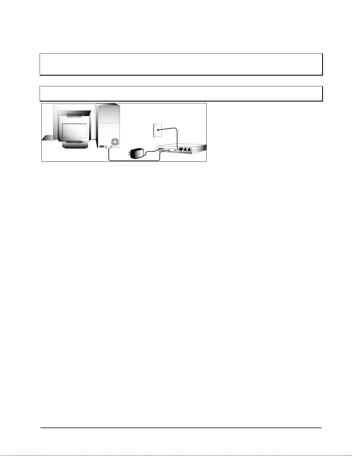
Quick Installation
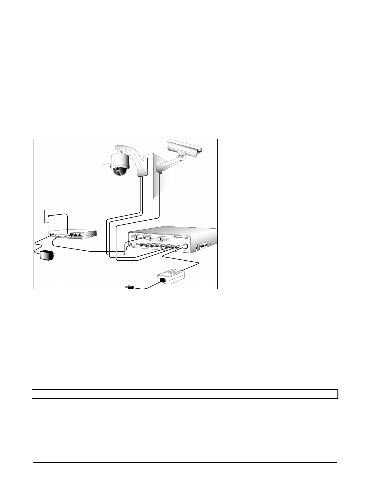
For experienced installers, follow these
steps for fast installation. Refer to Figure
4.
DV202S Transmitter/X-566
Modem
1. Unpack Transmitter and power
supply. Connect power supply to
Transmitter. Do not apply power yet.
2. Connect all cameras to Transmitter,
starting at CAM 1 position. If
necessary to loop any cameras out,
open cover and remove terminating
jumper from coincident input. Use a
BNC type T connector to loop input.
3. Unpack Modem and power supply.
Connect power supply to Modem.
Do not apply power yet.
4. Connect Modem to Transmitter as
follows:
a) Attach 25 pin cable side to
Modem.
b) Attach 9 pin cable side to
Transmitter’s
Communication Port #1.
5. Connect telephone line modular
connector to LINE IN socket on
Modem.
6. Power-on Modem and Transmitter.
Power-on LED should illuminate.
Yellow LED should blink for a few seconds and then remain off. If this LED remains blinking or is on solid,
there is a problem with modem initialization or unit itself. Recheck all connections and power-on condition
of modem.
Note: For connection to other devices or more installation details, refer to the Detailed Installation sub-section.
Figure 4
Transmitter/Modem Quick Installation
TX001-00-00 Rev 101 QuickSilver DV202S Video Transmitter Installation •
••
•5
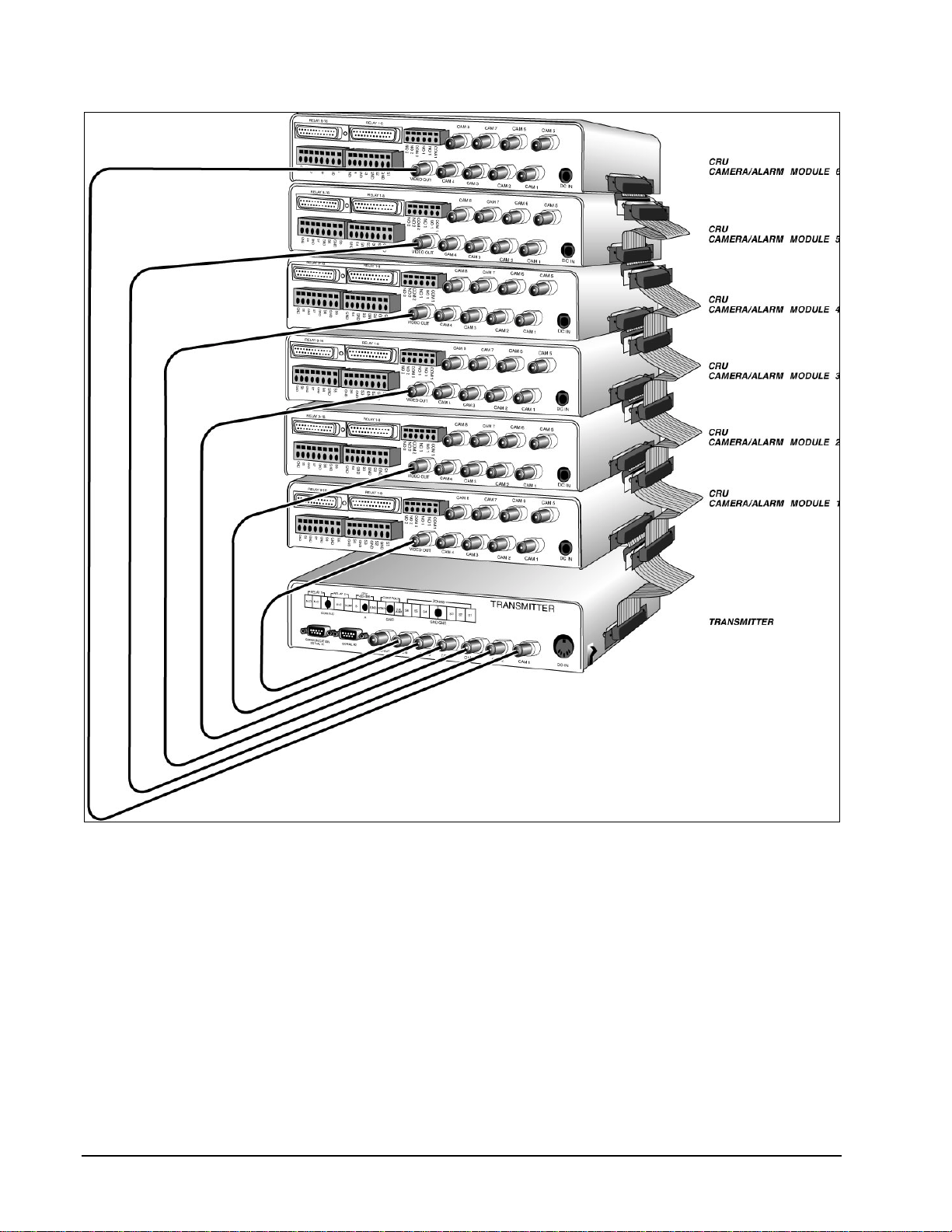
CRU
Refer to Figure 5.
1. Unpack CRU and power supply. Connect
power supply to CRU. Do not apply power
yet.
2. Place CRU on top of Transmitter.
3. Connect all cameras to CRU, starting at
CAM 1 position.
4. Connect coaxial jumper cable between
VIDEO OUT on CRU and CAM 6 on
Transmitter.
5. Connect 25 pin Ribbon Cable Assembly
between side of Transmitter and CRU at the
DB-25 sockets. If cable has more than 2
connectors, cut off the remaining connectors
with a scissor.
6. Open CRU by removing 4 side screws and
locate DIP switch SW1. Define the Module
number as in Table 1. Set DIP switch to
correct CRU address as in Table 2.
Note: All units are configured, from the factory
as Module number 1.
7. Reassemble CRU.
8. Power-on Modem, Transmitter and CRU. All
power-on LEDs should illuminate. Stacked
CRUs must be powered-on from the top
down. For example, Modules must be
switched on in the order #6, #5, #4, #3, #2,
#1. If Modules are not powered-on in the
correct order, the cameras attached to those
specific Modules may not appear in the
software’s camera list.
Note: Connect consecutive CRUs starting from
CAM 6 to CAM 1 as shown in Table 1. In
addition, verify that each CRUs internal
DIP Switch is configured as specified in
Table 2.
9. Calculate the number of CRUs required for
the number of video inputs on hand as
shown in Table 1. Stack additional CRUs as
shown in Figure 6.
10. Set the DIP switch address for each
additional CRU as shown in Table 2.
Note: Failure to configure additional CRUs as
shown can result in improper operation of
the system.
Figure 5
CRUQuick Installation
CAMERA ADD-ON
MODULE
NUMBER
CAMERA INPUT
NUMBER ON
TRANSMITTER
TOTAL SYSTEM
VIDEO INPUTS VIDEO CABLE
LENGTH in (mm)
1613 5 (127)
2520 10 (254)
3427 15 (381)
4334 20 (508)
5241 25 (635)
6148 30 (762)
Table 1
CRU Configuration
CAMERA ADD-ON
MODULE
NUMBER
DIP SWITCH 1
(SW1) DIP SWITCH 2
(SW2) DIP SWITCH 3
(SW3) DIP SWITCH 4
(SW4)
1ON ON ON ON
2OFF ON ON ON
3ON OFF ON ON
4OFF OFF ON ON
5ON ON OFF ON
6OFF ON OFF ON
Table 2
CRU DIP Switch Configuration
6 •
••
•Installation TX001-00-00 Rev 101 QuickSilver DV202S Video Transmitter
Figure 6
Transmitter Quick Installation
TX001-00-00 Rev 101 QuickSilver DV202S Video Transmitter Installation •
••
•7
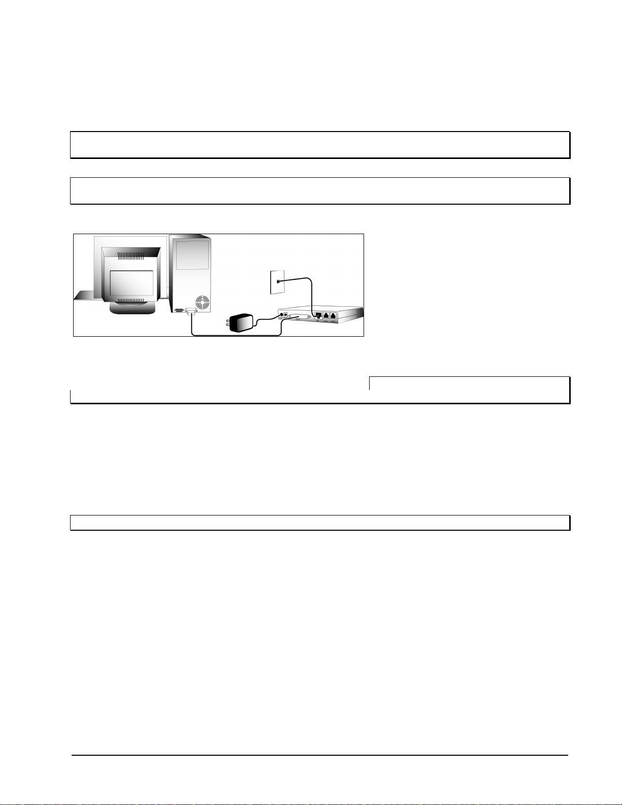
I-MODEM Modem
The installation of this Modem should be performed only if the X-566 (POTS/PSTN) is not being used. The
installation of this Modem is done in 2 subsections, Configuration and Operation. It is necessary to configure
the ISDN Modem, using a PC type computer, before attempting to connect to, and use with, the Transmitter.
Note: Review manual for Modem to verify that all requirements for ISDN line service are met before
attempting to configure Modem.
Note: Modem must be configured on-site and connected to actual ISDN line to be used before connecting to
Transmitter.
Configuration 1. Unpack Modem and power supply.
Connect power supply to Modem. Do
not apply power yet. Refer to Figure 7.
2. Connect Modem to computer by
attaching one of the DB-25 connector
ends on provided cable to Modem’s
serial port labeled TO DTE. Connect
the remaining connector end to
computer’s serial port. If the computer
has more than 1 serial ports available,
COM2 should be used.
Note: If the computer is equipped with a
DB-9 connector for its serial port, use the provided 25 to 9 pin adapter included with the Modem.
3. Connect one end of telephone cable (RJ-45 modular connector) to ISDN socket on Modem and the
remaining end to the ISDN wall socket.
4. Power-on Modem and verify that Modem Power LED illuminates solid. In addition, verify that Modem
initializes by verifying the following LEDs:
a) All LEDs should illuminate briefly to verify that they function.
b) DSR LED should illuminate solid to verify that Modem is ready for operation.
c) LNK LED should illuminate at a fast blinking rate. This state verifies that Modem has detected a valid
ISDN line and is searching for more identity information.
Note: If Modem fails to initialize, refer to Modem manual for error codes and troubleshooting.
5. Power-on computer and go to Microsoft Windows operating system.
6. Refer to Configuration section of Modem manual and follow instructions specific to computer operating
system. When complete, the following items should be complete:
a) correct ISDN Modem driver is installed.
b) correct ISDN telephone numbers are entered.
c) correct ISDN switch type is entered.
d) correct ISDN SPID numbers are entered.
7. Software will respond with a successful link message when a successful connection is made. If a
connection error message appears, refer to Modem manual Troubleshooting section.
8. Power-off the computer and ISDN Modem.
9. Disconnect DB connector from computer. Attach 25 to 9 pin Adapter to the end, if required.
Figure 7
ISDN Modem Configuration
8 •
••
•Installation TX001-00-00 Rev 101 QuickSilver DV202S Video Transmitter
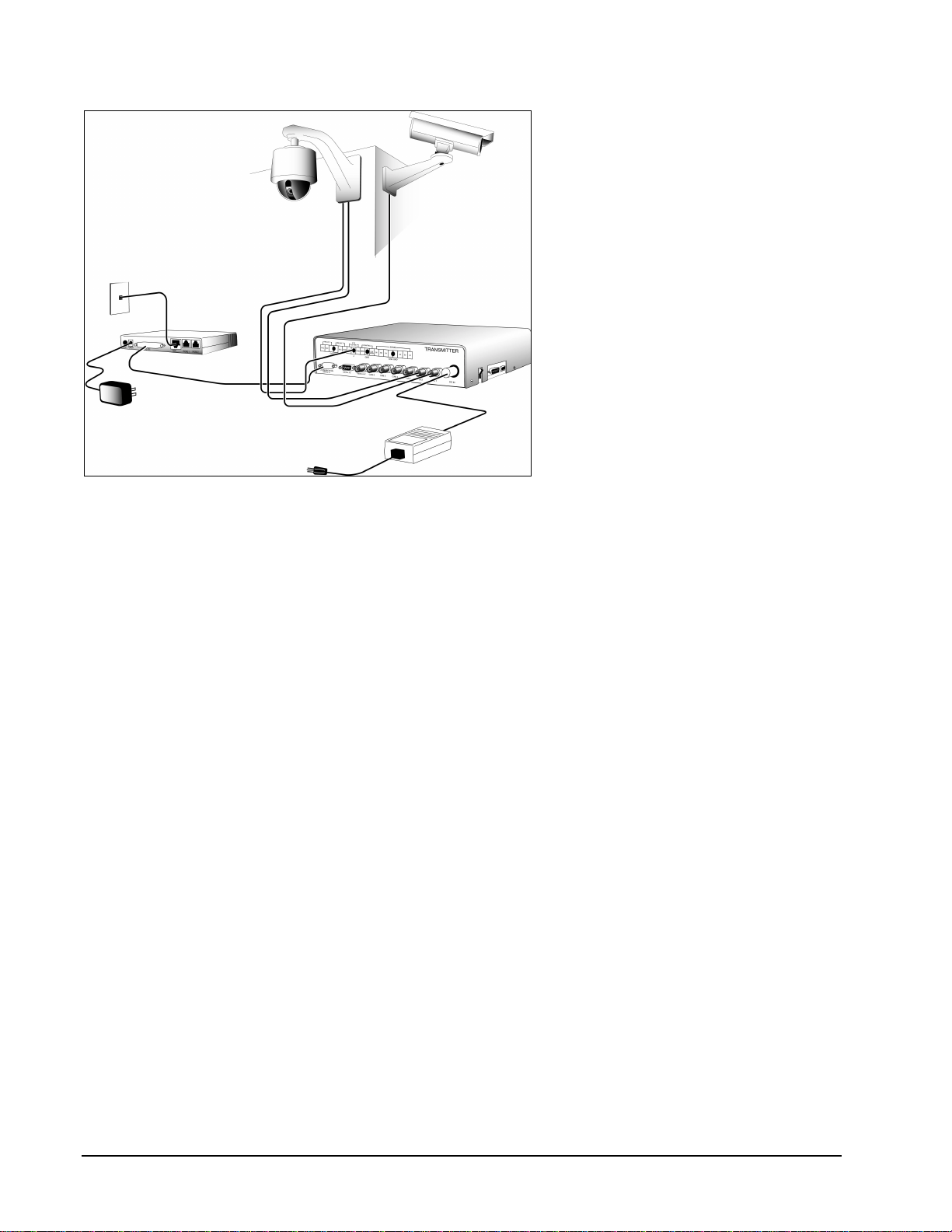
Operation
1. Attach DB-9 connector of Adapter to
Transmitter’s Communication Port #1.
Refer to Figure 8.
2. Power-on Modem and verify that
Modem Power LED illuminates solid.
In addition, verify that Modem
initializes and detects the ISDN line by
verifying the following LEDs:
a) All LEDs should illuminate briefly
to verify that they function.
b) DTR, DSR, RTS, CTS, TX and RX
LEDs should routinely blink during
line detection.
c) LNK LED should illuminate at a
slow and, later, fast blinking rate.
Soon thereafter, it should
illuminate solid, indicating that
Modem has linked up with ISDN
line.
3. Power-on Transmitter. Power-on LED
should illuminate. Transmitter is now
ready for dial-in use.
Figure 8
ISDN Modem Installation

TX001-00-00 Rev 101 QuickSilver DV202S Video Transmitter Installation •
••
•9
Detailed Installation
This sub-section will detail the installation of QuickSilver in a variety of configurations. The installer has the
choice of using the X-566 PSTN type or I-MODEM ISDN type Modem, based on the installed line type. In
addition, this sub-section will detail the setup of direct (RS-232) connection from Transmitter to Receiver. This
is used to verify the correct operation of a new installation. This sub-section also details the installation of the
CRU CRU and its option boards. Lastly, this sub-section will describe the installation of the AUDIO-BD Audio
Card.
Installation can be summarized with the following steps:
1. Unpack the components and prepare the remote site for hardware installation.
2. Install, wire and configure all components at the remote site.
3. Verify the power-on condition of all components at the remote site.
4. Install and configure the software on the Receiver at the local site.
5. Proceed to the Operation section and verify proper connection and installation to the remote site.
DV202S Transmitter/X-566
Modem
The Transmitter must be connected with
the proper cables to the Modem, camera
and alarm inputs and relay outputs. The
following procedure provides steps for a
typical remote site installation. Refer to
Figure 9.
Note: Do not apply power to the remote
site equipment until all cabling has
been completed.
1. Unpack the Transmitter and Modem
and find a convenient location for the
installation.
2. Connect the DB-9 end of DB-9 to DB-
25 Serial Cable to the Communication
Port #1 on the rear panel of the
Transmitter.
Note: Throughout this procedure, verify
that the screws are securely fastened on all DB type connectors. Route all cables conveniently between
the devices to avoid sharp bends and excessive stress on the connectors. The use of anchored tie-
wraps is highly recommended. It is also good practice to clearly label all cables for identification.
3. Connect the DB-25 end of the cable to the rear panel serial port of the Modem labeled RS-232. For the
I-MODEM Modem it is labeled TO DTE.
4. Connect all camera video outputs to their corresponding camera input BNC type sockets (CAM1 - CAM6)
on the rear panel of the Transmitter. Camera input sockets CAM1 - CAM6 correspond to Receiver
Software Camera numbers. For example, socket position CAM1 corresponds to Software Camera 1. If it
is necessary to loop any cameras out, open the cover and remove the terminating jumper from the
coincident input. Use a BNC type T connector to loop the input.
Figure 9
Transmitter/56 Kb
p
s Modem Installation

10 •
••
•Installation TX001-00-00 Rev 101 QuickSilver DV202S Video Transmitter
5. Connect the telephone cable to the socket labeled LINE, or TELCO on the Modem. Orient the tab into the
slot and press the RJ-11 plug straight in to the socket until a snap is heard, indicating that the two
connectors are locked. If it is desired to share this line with a telephone, connect a standard telephone RJ-
11 plug to the socket labeled PHONE on the Modem. For the I-MODEM Modem, the telephone socket is
labeled ISDN and is an RJ-45 type. A standard telephone can be plugged into one of 2 telephone cable
sockets labeled PHONE1 and PHONE2 that are RJ-11 type.
6. Connect the provided power supply cable DIN type plug to the DC IN socket on the Transmitter. Line up
the plug and socket pins and press the plug straight into the socket. Connect the female end of the
provided AC power cord to the power supply and the male end into a convenient AC wall receptacle.
7. Connect the provided power supply cable coaxial plug to the DC power socket on the Modem and the AC
plug into a convenient wall receptacle.
8. It is recommended to recheck all wiring for accuracy and stress points. If necessary, create harnesses
with individual cables and use tie wraps to hold them securely to designated anchor points.
9. Power-on the Modem and Transmitter. The Power-on LEDs should illuminate. For the specific LED
sequence of the ISDN Modem, refer to the specific ISDN sub-section. The yellow LED on the Transmitter
should blink for a few seconds and then remain off. If this LED remains blinking or is on solid, there is a
problem with modem initialization or the unit itself. Recheck all connections and the power-on condition of
the modem.
10. Refer to the Operation section of this manual.
TX001-00-00 Rev 101 QuickSilver DV202S Video Transmitter Installation •
••
•11
I-MODEM ISDN Modem
Note: Review the manual for the Modem to verify that all requirements for the ISDN line service are met
before attempting to configure the Modem. The basic configuration requirements for the highest speed
operation (approximately 115 Kbps) is a line containing 2 B type channels, bonded.
Note: The Modem must be configured on-site, using a PC type computer, and connected to the actual ISDN
line to be used before connecting to the Transmitter. 1. Unpack the Modem, power supply and
cables. Verify that the Modem power
switch is in the OFF (down) position.
Connect the power supply to the
Modem by inserting the supply’s
coaxial plug into the Modem’s socket.
Insert the supply’s AC plug into a
convenient receptacle. Do not apply
power yet. Refer to Figure 10.
2. Verify that the computer is powered-
off. Connect the Modem to the
computer by inserting the female end
of the provided 25 pin cable to the
Modem’s serial port labeled TO DTE.
Connect the male end to the
computer’s serial port. If COM2 port is
available, it should be used.
3. Connect the Modem to the telephone
wall socket by inserting one end of the telephone cable plug (modular RJ-45 connector) into the ISDN
socket on the Modem and inserting the remaining end into the ISDN wall socket.
4. If it is desired to share this line with a telephone, insert one end of a standard telephone RJ-11 to RJ-11
cable into the socket labeled PHONE 1 or PHONE 2 on the rear of the Modem and inserting the remaining
end into a standard PSTN telephone.
5. Power-on the Modem and verify that the Modem initializes and the Power LED illuminates solid. In
addition, verify that Modem initializes and detects the ISDN line by verifying the following LEDs:
a) All LEDs should illuminate briefly to verify that they function.
b) The DTR, DSR, RTS, CTS, TX and RX LEDs should routinely blink during line detection.
c) The LNK LED should illuminate at a slow blinking rate. This state verifies that Modem has detected a
valid ISDN line and is searching for more identity information.
If this fails to occur or other LEDs remain flashing, refer to the Modem manual for error codes and
troubleshooting.
6. Power-on the computer and go to the Microsoft Windows operating system. If the Modem software has
not been installed and configured, refer to the Modem manual for instructions.
Figure 10
ISDN Modem Configuration
12 •
••
•Installation TX001-00-00 Rev 101 QuickSilver DV202S Video Transmitter
7. Verify that the following information has been correctly entered during configuration.
a) Verify that the correct Modem driver is installed.
b) Verify that the correct telephone numbers are entered.
c) Verify that the correct switch type is selected.
d) Verify that the correct SPID numbers are entered.
8. The software will respond with a successful link message when a successful connection is made. If a
connection error message appears, refer to the Troubleshooting sub-section of this manual.
9. Power-off the computer and the ISDN Modem.
10. Configuration of the modem is complete. Disconnect the DB connector from the computer. Attach the 25
to 9 pin Adapter to the end, if not already in use.
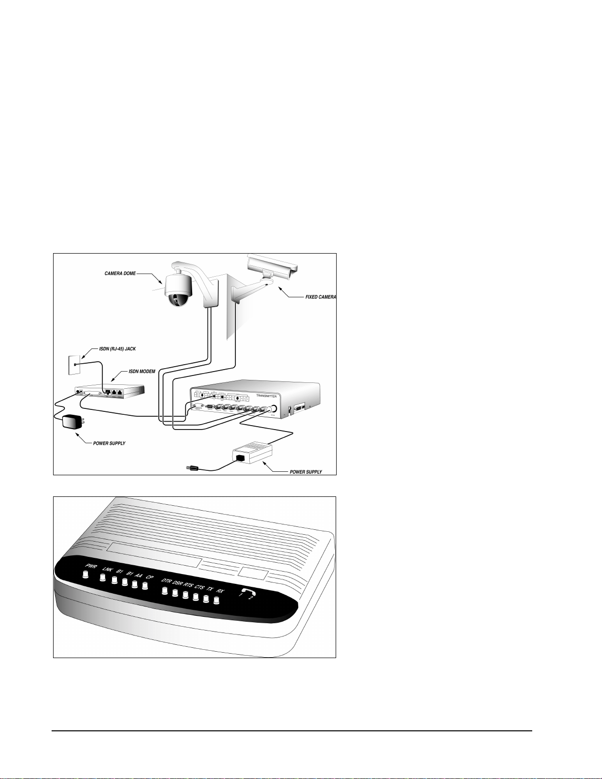
Operation Refer to Figures 11 and 12.
1. Attach the DB-9 connector of the
Adapter to the Transmitter’s
Communication Port #1.
2. Power-on Modem and verify that
Modem Power LED illuminates solid.
In addition, verify that Modem
initializes and detects the ISDN line by
verifying the following LEDs:
a) All LED’s should illuminate briefly
to verify that they function.
b) The DTR, DSR, RTS, CTS, TX
and RX LEDs should routinely
blink during line detection.
c) The LNK LED should illuminate at
a slow and, later, fast blinking rate.
Soon thereafter, it should
illuminate solid, indicating that the
Modem has linked up with the
ISDN line.
3. Power-on Transmitter. Power-on LED
should illuminate. The Transmitter is
now ready for dial-in use.
Figure 11
ISDN Modem Operation
Figure 12
ISDN Modem Front Panel
Table of contents


