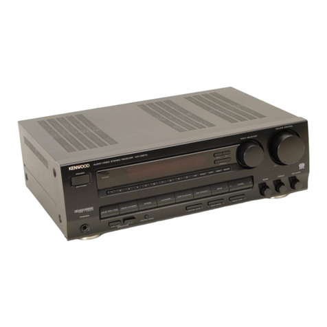
Teleton CS-400 User manual

SERVICE
MANUAL
Hi-Fi
LW/MW/SW/
FM
Stereo
Receiver
with
Disk
Player
MODEL
CS—400
YY td
Alp
Hi
i
ae
7
Hotes
y
sayy
ay?
lees
(Edition
B)
Jan,
1975
TELETON
Electro
GmbH.
+
Co.
KG
4000
Dusseldorf-Rath
Oberhausener
Str.
17
Tel.
(0211)
65
30
81
TX
858
6768
TELETON
Electro
(UK)
Co.,
Ltd.
Teleton
House,
Waterhouse
Lane,
Cheimsford/Essex
Tel.
Chelmsford
62
442
TX
93
338
Technical
Service
Organization
Waterhouse
Lane,
Chelmsford,
Essex.
Tel.
0245-54621
TX
99338
TELETONN.
V.
2200
Borgerhout
Prins-Leopold-Straat
28
Tel.
03/361045
TX
32508
03/357670
Belgium
TELETON
NEDERLAND
Nieuwe
Herengracht
119
Tel.
24
83
81
Amsterdam
TELETON
Electro
(France)
S.a.r.|.
21
rue
Paul
Lafargue
94
Kremlin-Bicetre
Tel.
726
4091
TRANSACO
AG
Kanzleistrasse
126
8004
Zurich
Tel.
39
45
60/23
5040
TX
52
362
For
disassembly
please
see
exploded
view.
ADJUSTMENT
INSTRUCTIONS
1.
Adjustment
of
Main
Amp.
When
transistors
Q311,
312,
313,
314,
315,
316,
317,
318
are
exchanged,
the
following
adjustment
is
necessary:
1-1
Measuring
Equipment
(a)
DC
Current Meter
(100mA
Maximum)
(b)
Oscilloscope
(c)
Dummy
load
30W
1-2
Condition
of
the
Set
Middle
Position
(a)
Treble
..........
(6)
BaSS-
fo
oar
-a-
kh
2
ee
Middle
Position
(c)
Volume
........-.-.
Minimum
(d)Balance
..........
Middle
Position
(e)
Muting,
AFC,
Loudness,
High
Filter,
OFF
Position.
(f)
Mode
Switch.
.......
Stereo
(g)
Function
Switch.
.....
AUX
(h)
Speaker
Switch
......
A
or
B
(i)
Tape
Monitor
Switch
.
. .
ON
1-3
Adjustment
(a)
Set
VR301.VR302,
VR303,
VR304
to
meckanical
cen-
ter
Position
(AA-400
P.C.
board)
.
(b)
Connect
the
DC
Current
Meter
to
Fuse
Terminal
(AA400
P.C.
Board
L
or
R)
@:
Terminal
No.
21
©:
Transistor,
collector
side(
L:
Q315
R:
Q316)
(c)
Adjust
VR303(L)
or
VR304(R)
to
obtain
17MA
+
3mA.
(d)
Repeat
procedure
(a)
~
(c)
several
times.
(e)
Add
the
signal
of
1000Hz,
G(OOmV
~1V
tp
tape
input,
and
adjust
Volume
Control
for
Clipping
level
of
speaker
(or
dummy)
output.
(Tape
Monitor
Switch
:
ON
Mode
Switch
:
MONO)
(f)
Adjust
VR301(L)
&
VR302(R)
to
obtain
the
symmetrical
sin-wave.
(g)
Repeat
procedure
(e)
~
(f)
several
times.
2.
AM
|
F
Adjustment
2-1
Measuring
Equipments
(a)
AM
Standard
Signal
Generator
(b)
Output
Meter
(V.T.V.M)
(c)
Oscilloscope
(d)
Dummy
Load
82.
30W
2-2
Preparation
of
Adjustment
(a)
Volume:
Max.,
Mode:
MW,
Others:
same
as
procedure
1-2
(b)
Measuring
Connection
is
as
follows:
AMF
-400
AM
Frantend
P
C
Board
Terminal
®
Osedh
te
ope
{——-
-4
Dummy
{oad
10K
9.01
anna
“eemmes
¢
0
Be
Bee
oe
a
ee
med
Seep
Sete
eee
ce
oS
C.
;
dons
BQ
i
[SB.QU1
HOW
Le
Ssteaedaesd
‘eo
dial
Generator
Figure
1
VAIOA
1K&
|
|
:
I1C103
LASIOO
T104
O
mu
CFU-1002
8}
bd
GN10390
Pee
;
TP2
sre
(¥]
Ne
ei
5
navies
T10:
T1108
C)
Olas
OM
K112
©
T109
L102
K413
THO
WM
14033
1101
TPI
T105
C24
IQ
9
Tt06
T107
JVR103
aa
cay
50K82
HF-400
IF
P.C.
Board
Figure
2
2-3.
Adjustment
(a)
Set
S.G.
to
460
KHz
(Mod,
400
Hz
30%)
80
dB,
and
adjust
IF
cores
of
T1104
and
T105
for
maximum
output
reading.
(See
Figure
2)
Adjust
the
Attenuator
of
S.G.
according
to
increase
the
output,
and
put
the
output
reading
to
500
mW
(2V).
(b)
Repeat
procedure
(a)
several
times.
i
AM
Tracking
Adjustment
(Adjusting
procedure
for
LW,
MW,
and
SW)
(See
AMF-400
AM
Frontend
P.
C.
B.
)
3-1
Measuring
Equipments
(a)
AM
Standard
S.G.
(including
loop
antenna)
(b)
Output
Meter
(V.T.V.M.)
(c)
Oscilloscope
(d)
Dummy
Load
82
30W
3-2
Preparation
of
Adjustment
(a)
Volume:
Max.,
Mode:
LW,
Others:
same
as
protedure
1-2
(b)
Measuring
connection
is
as
follows:
MW.
LW
SP
4
ohn
Bar
Antenna
OSC
Uta
se
apie
Mod.
400
2.4%
Figure
3
Figure
4
(c)
TC201,
TC202,
TC203,
TC204,
TC205
and
TC206
Position
are
as
shown
in
Figure
4.
Note:
All
adjustments
for
rnax.
Output.

3-3.
LW
Tracking
Adjustment
(Function
Switch:
LW)
3-3-1
Adjustment
of
Local
Osc.
circuit
Adjustment
Step
|
Frequency
(S.G.)
1
145
kHz
Min.
Capacitance
V.C.
Position
Max.
Capacitance
Adjust
Point
Repeat
Step
1
and
2
several
times.
When
step
1
and
2
match,
adjustment
of
the
Local
Osc.
Circuit
is
finished.
3-3-2
Adjustment
of
Tuning
Circuit
Adjustment
Step
Frequency
(S.G.)
Adjust
Position
320
kHz
Tuning
Position
160
kHz
Tuning
Position
T601
LW
Tuning
Coil
(Bar
Ant.
)
re
ene
nee
terrane
Repeat
step
1
and
2
several
times.
When
step
1
and
2
match,
adjustment
of
tuning
circuit
is
finished.
Fix
the
LW
Tuning
Coil
with
wax,
and
adjust
finely
the
Local
Osc.
Circuit
(because
the
coverage
drag
by
the
Tracking
adjustment.)
3.4
MW
Tracking
Adjustment
(Function
Switch:
MW)
3.4-1
Adjustment
of
Local
Osc.
Circuit
Max.
Capacitance
Min.
Capacitance
3-4-2
Adjustment
of
Tuning
Circuit
Adjustment
Step
1
a
eee
600
KHz
Tuning
1400
KHz
Tuning
Position
Position
‘
ay
MW
Tuni
Adjust
Position
roo
Bee
TC206
Coil
(Bar
Ant.
)
3.5
SW
Tracking
Adjustment
(Function
Switch:
SW)
S.S.G.
Signal
input:
AM
External
Antenna
(through
IEC
Dummy
Antenna)
3.5-1
Adjustment
of
Local
Osc.
Circuit
V.C.
Position
3-5-2
Adjustment
of
Tuning
Circuit
7
MHz
Tuning
11
MHz
Tuning»
Position
Position
V.C.
Position
Adjust
Position
FM
IF
Adjustment
(See
Figure
2.)
4)
Measuring
Equipment
(s)
10.7
MHz
Interscope
(Sweep
Generator
and
Scope)
(b)
Detector
Probe
4-2
Preparation
of
Adjustment
(a)
Eunction
Switch:
FM
(manual)
(b)
FM
AFC
Switch,
FM
Muting
Switch:
OFF
-
ian
mn
$ntiarvare:
Cpu?
PSE
BEC
+
|,
ai
Input
QlO2
Base
jw
Overall
Response
Tout
in
C)
|
to
Q102
Base:
Figure
5
Note:
1.
Keep
output
lead
and
input
lead
at
a
distance.
2.
Ground
of
the
output
and
input
lead
should
be
done
near
point
of
hot
side.
4-3.
Adjustment
Overall
Response
(a)
Draw
the
secondary
core
of
T110
fully.
(b)
Adjust
1102,
103, 106,
107,
108,
109
and
T110
to
obtain
the
best
overall
response
(Fig.
6-a).
(c)
The
input
signal
should
be
appeared
small
unless
the
wave-
form
fade
away
by
the
noise.
(d)
The
waveform
should
not
change
by
input
level.
S
Curve
(a)
Adjust
the
secondary
core
of
T110
to
obtain
the
best
S
curve
(Fig.
6-b).
(b)
In
above
adjustment,
when
the
best
S
curve
does
not
obtain,
adjust
T102~T110
somewhat.
(c)
When
above
(a)
&
(b)
finished,
observe
the
overall
re-
sponse.
If
the
waveform
drag,
check
the
S
curve
again.
10.7
MHz
Maker
10.8
MHz
10.6
MHz
10.8
MHz
My
MMW
10,7
MHz
Maker
Wn
(a)
10.6
MHz
(b)
Overall
Response
S
Curve
Figure
6
5.
EM
Tracking
Adjustment
(See
Figure
2.)
5-1
Measuring
Equipment
(a)
FM
Standard
Signal
Generator
(include
the
pad)
(b)
Output
Meter
(V.T.V.M.)
(c)
Oscilloscope
(d)
Distortion
Meter
(a)
Dummy
Load
82
30W
5-2
Preparation
of
Adjustment
(a)
Volume
-----
Max.
Function
Switch
----
FM
(b)
Measuring
connection
is
as
follows.
SP
82
FM
Standard
:
,
ae
ee
et
Sigrast
‘oil
£
i
Gener
ator
2+
5082
:
yn
Ant.
a
CH
}
aac
eee
Gee
Se
Se
i
ul
Dummy
Load
Mod.
400Hz
75KHz
Dev.
SPOUT
4
oo
Wits
cde
Figure
7
(c)
TC101,
TC102
and
TC103
position
are
as
follows.
Figure
8

(d)
Set
VR101,
VR102
and
VR103
to
mechanical
center
position.
le)
Set
Pre-Set
Switch
(Pre-Setter)
to
MANUAL.
5-3
Adjustment
5-3-1
Adjustment
of
Local
Osc.
Circuit
(a)
Connect
@
terminal
of
Voltmeter
to
HF-400
1F
P.C.Board
terminal
(7),
and@©
terminal
of
Voltmeter
to
chassis.
(b)
Set
tuning
to
max.
frequency
and
adjust
VR102
for
9.5V
Voltmeter
scale.
(c)
Set
tuning
to
min.
frequency
and
adjust
VR101
for
2V
Voltmeter
scale.
(d)
Repeat
step
(b)
and
(c)
several
times.
When
step
(b)
and
(c)
match,
voltage
adjustment
is
finished.
(e)
Adjustment
of
tuning
circuit
Max.
frequency
Adjust
for
max.
output.
Repeat
step
1
and
2
several
times.
When
step
1
and
2
match,
adjustment
of
the
Local
Osc.
Circuit
is
finished.
5-2-2
Adjustment
of
Tuning
Circuit
rrequency
(SG)
|
90MHz
|‘
102MHz__|
90
MHz
Tuning
|
102
MHz
Tuning
Position
Position
Faint
Pome
|
Taoncioa
|
ror.
Te102
|
6.
Adjustment
of
Meter
(See
Figure
2.)
V.C.
Position
6-1
Adjustment
of
Meter
Input
96
MHz
(Mod.
400
Hz,
22.5
kHz
Dev.)
100dB
(Att.
scale),
and
adjust
VR103
for
4
Meter
scale.
7.
MPX
Adjustment
(See
Figure
2.)
7-1
Measuring
Equipment
(a)
FM
Standard
Signal
Generator
(S.S.G.)
(b)
FM
Stereo
Signal
Generator
(MPX
S.G.)
(c)
V.T.V.M.
(d)
Oscilloscope
7-2
Preparation
of
Adjustment
(a)
Volume
-----
Adjust
output
of
L
ch.
and
R
ch.
for
500mW
(2V).
|
(b)
Bass,
Treble
Control
.....
Center
(c)
Loudness,
Hi-Cut
Filter,
FM
AFC,
FM
Muting
Switch
2
OFF
(d)
Mode
Switch
-----
Stereo
(e)
Function
Switch
---
FM
(manual)
(f)
Set
VR104
1K%2
Semi-fixed
volume
to
center
position.
Zin
as
2
L-
R
Selector
Switch
°
FM
MPX
SG
tek
:
Rare
~
WT
VLM.
Oscilluscope
t
[
Figure
9
FM
SSG
Open
Output
Voltage
94
MHz
4mV
Modulation
Frequency
:
400
Hz
Modulation
Factor
-
tL+R
90%
(67.5
kHz
Deviation)
Pilot
Signal
10%
(7.5
kHz
Deviation)
Input
Voltage
:
ImV
Load
:
8a
(30W)
Output
-
5OOmW
(2V)
7-3.
Adjustment
(a)
Set
SSG
to
94
MHz
(L
+
R)
+
Pilot
to
ImvV.
(b)
Tune
set
to
94
MHz.
(c)
Connect
V.T.V.M.
to
terminal
(1)
of
{C103
through
47
kohm
resistor.
(d)
Adjust
L105
(19
kHz,
orange
coil)
for
maximum
voltage.
tr
Black
Figure
10
(e)
FM
MPX
SG:
(L.—-R)
+
Pilot
(¢)
Adjust
L106
(38
kHz
black
coil)
for
max.
output
and
min.
distortion.
Tuning
Point
appears
two
point,
there-
fore
adjust
with
first
tuning
Point.
(If
you
adjust
with
second
tuning
Point,
L
&
R
appears
opposite
side).
(g)
FM
MPX
SG:
R
+
Pilot,
Set
output
L.
(h)
Adjust
VR104
(1k)
for
minimum
output
waveform.
(i)
FM
MPX
SG:
L
+
Pilot.
Set
output
R.
(j)
Adjust
VR104
(1kQ),
for
minimum
output
waveform.
(k)
When
the
difference
of
L
and
R
Separation
is
more
than
6
dB,
turn
1106
finely
to
lessen
the
difference
of
Separation
between
L
and
R.
(1)
If
the
waveform
is
abnormal
in
L
side
with
L+19
kHz,
and
the
Separation
is
unbalance,
adjust
again
for
I.F.
and
check
the
MPX
circuit.

AA—400(Audio
Pre.
Main
Amplifiter)P.C.Board
f°
(fi)
33/36,
BN
1n0/In
Cala
"fy
—
‘
24°58
Jorne
Cs)
"
3
4
‘
:
Y
"Qaraar2
100
|
27k
,
Bove
_
Fro
bs
.
[560
;
-
YU
wht
ee
c
R380
3K,
=
-
§@:
ee
r
36,3
72
R306
.
a
82K
Wow
nen
F
“
R3O4R
906
ASIG
AZIB
R326
|
42
«82.2%
R390
0302
|}.
se
'
TOOK
150K
a70-
ae
oar
8K
Sand
GOK3ai6
e
Mgt
eet
©1407,
Ps)
327
BK
10/38
96
bg
R355
1.5K
:
1
(1/2)
&
/2W)
,
eye
369
;
)
A
aes
:
oe
be
Ae
PAB
AA
OF
100K
cok
470
6RDK.
Gop
We
80
WA
750150
GIR
YPN
WG
207
eH
PSCSIH
FW
oo
ASC
7
42GIR
Yr
yyy
Gt
442
2SCVWA
A/K
ping
ts
256A
OI
Bee
rN
me
GREEN
it
ee
2
Cy
a
Low
ECB
ECB
ECB
ECB
ee
oS
ot
é
Om
t
ae
t
ae
PLP
—
c
7
t
031%~0318
paced
250883
FU
2SC.1090.GR
2SC1175
F
2SC1384-A
ISDUID
MV
1a
2SC536
F
250732
GR
2SA6A4-R
Switch
P.C.Board
(Conponent
side)
Push
Swot
th
AF
cee
Pavey
C218
Pp
C219
3.02
R215
&
8.2K
—<—>-~
C216
0,04
O—
—-
R219
:
VK
C)
3203
Orm
10K.
0006GC90
0000
00000000
0
mu
PP
Sot
A218
22
aaO
22K
o00o00g0cn0000
0 0
(oo
uO
©
On
©
OO
©
EO
ORC)
2ec>0
0o0O0o
0000
00
000
o0o0o0o0o0cg0
0000
0
n
u
Ec
8
e
2S8C
10470
2SC1389C
R214 R234
6BK
33K
?
9
Cc
B
"
s
C278
dog
2
HCOK
C230
16
20
02
ECB
om
2SC1000—GR
C215
0.94
<>
R2v1
2k
og
“<>
8.2K
R206
wK
me
|.
7
Switch
P.C.Board
o
(Copper
side)
AMF-—400(AM
Frontend)P.C.Board
2.
ad
ky
ae.
o
o
‘
aS
54
GG
4
A
centr
mae
.
Sx
és
\
Yok.
Xe
a
4
ae
§2
:
"
A
\
at
oi
ao
amen
y
\
”
vee
Ose
=
tas
RS
\N
Ae
OX
wee
ae
oa
Fi
sx
Sa
YO
.
co
oe
:
ge
eee
g®
rs
mere
hae
a
:
\
SS
x.
me
\
\
Peat
Po
aut
4
Ly
N
VO
:
7
ee
“SN
os
See
2
ae
2
Iw
CO
S
Xo
©
CSB
“OOS
Qg
0
ER
OS
i
a
oO
Do
°
ae
te
OOS
suas
so
wo
0
ACB/oU
2
0
es
§8
NS
8
BERRe
Mond
Go
0
©)
Aste
a
D
\
2-3}
LAD
__0
PO)
Se
3h
eR
oS
She
a)
€
ero
>
seo
oo
y
1
ERS
AS
|
Oy
\Q
a
NGy
;
x
¥
€
rcand
bl.
a
pes
we
2
.
|
O
I
o
CO
SO
Gee
o
zo
on.
C2
OO
Oo
oO
pea?)
Be
=
M
)
2
0S
Ri
(oS)
SRLS
[P-
oo)
oh
A
cee
Aa
ao
/O
&
rn
6
aie
1.8
,
f
o
Vanes
‘

HF—400(rMVi
Frontenad
Fivi
AVE
iF
PAGEIpiNiteet
SWE
BW
ek
Fd
or
eee
Sky
Blue
-eu8
nite
o1OL!,
SPP
420K.
1821368:
=
ers
‘O
10?
AIO2
;
ies
eK
PR
Antenna
Tearetarinee
Leary
stirs
At
x
1K
198
OOP
M3
IGE
128A
/
isd
251,
2100
|
2
tae,
ta
WOT
SU
de
fc
8
b
G
é
8
!
S
£€
Cc
8
:
oes
—
CE
2S
19GR
C
:
28C3)2-
28C1359--C
‘yey
Bat
Pint
lamno
TOA—400(Tone
control
Volume
Amplifier)P.C.Board
a
ee
ele
Aeoz.
8.2K
—C——-.
PS-400(Power
Supply)
P.C.Board
—O =@
eu?
ps
se
A701:
C508
C510
Deus
.
ADS
0.04
D504
psu
}o04
RSO4
Rpie
jPd06
4.7K
HF
ok
ee
[2
SHEENA
SPECIAL.
'O)
1©
Sores
<)
)
Rae
ave
Xe
c
yy,
ele
r
050
a
TAA
9408
cues
|
s
NTs.)
28C
1384
*
.
.
ig
soa
0502
Dh.
\
Penis
tae
9.04
Wor
nae
"
Pe
ae
3
+
paat
oso?
,
@)
a
TS
toca
;
Hes
HiFi
P
;
7
VR4Ot
:
a
vRe2
n
—
+
40
ne
”
SOK!
BSOKNI
«2
y
Rage
8.2K
BSOKii
a2
PETAL
SPECIAL
@-
©
-@
“©
‘toe
ye
Marys
Chay
on
=O
=O)
a

DIAL
STRINGING
PULLEY
“6
STRINGING
RING
EYELET
PULLEY
SPRING
|
SMALL
PULLEY
a
(8)
@@)
&
=k
x
)
Gas
a7
a
N
2)
®
MIA
Gad01dX4
YAAV
1d
SIC

Q107
2SC372Y
{
L601
:
y
7
a
asi
ST
INDICATOR
R160
470
C165,,01
12v
40mA
HF
-
400
ee
2SKI9GR
Q102
2SC1359C
Q104
2SC930
D
-
AM
ie
_
6
METER
67
63
Taner
(O)
—
eee
ee
—_
=_—.
SS
Oe
iS,
Sennen
Socal
————————
i)
va)
C102
103
R102
C106
C114
;
TO105
2S5C372Y
25
A:
|
IP
Kt}
ee
a
Ar
100K
;
c1as
{va103
sang
M-
085
p,
R13
T105
1101
sai
ge
33
re
oF
Jose
ae
Bae
4.7K
C28
ml]
SRS
a
ee
ie
Ol
a
i!
5
nt
il
C175
a2
R132
10K
|
op
=)
;
MN
RIG
ut
i
C105
2
ee
AL
ig
Ke
36
|3.
a
oo
=
C130,
0.04
‘
R105
3
0302
100
a
a
RIGl<
0301
100K
1S1503SR
5.6K
100K
|
1S1503SR
VR1O2
R104
C119
@RI18
0104
YRIO}
50KB
_
330
5P-10PCHS
470K
1S2139-b
R113
RI9
RZ}
2
5
Jens
100K
R114
3.3K
$47
Wr
100K
f=
2
l
0
ae
cli?
RIS
ay
123
7
—Tlhsv_{0.01
MWe
L104}e
co
10120
iws
Oz
LT
fF
hrc
s
100
{103K
FB
Tous
scizi
‘B|
|
1$1503S0|
|
[5P-uns
15P
3
@
Rig
RINT
33K
3.3K_
R613
9103
pais
C
10%
GN-1039D
S
R135
oO
INGOP
~
R152
R154
C158
R155
ik
10K
100P
e
3
3
_
op
_
8:
0109
IN60
B3ENOI02
C169}C170
|c17
560P/560P
0202
HF
19
Heist
Jy
AMF
-400
3§¢82
29B/c___2SC829B
_
5
R202,,,
IK
R204
330
Q2024"-
C204
I/16V
n209
10K
—R212,1.5K
c2i3
S2l
ay"
C212
haa
ay
01
Ay
1.8
30Pp
Ag
uoMo
”
9203
2SC829C
'0204
|
2SC1047D
MPX.R.
OUT
Q301~304
Q401.402:
:
200P
C201]
2
1
;
AM
ANT
MW
2.2K
C208
te
ee)
2
2SC1O000GR
2SC536F-W
2SC536F-W
1202
C2i1
fe
R313
DK
R327
R328
0.02
2.2K
1.8K
a
Q205
2§C13598
12003
VR303
LR
9205
|
R229
100
03
12
x
Or
|
{335
>
is
ey
0.057
|
Ps
.
Q317
R413
es
R605)"
Apoat
R404-a
5
R345
0333+
0383
9365
R369
oe
pay
.
OKB
R343
6.8
100°
4705
6.3¥
ah
ty}
VR4O2-2}
gor
S|
[6K
eae
fied
coir
Side
Rasir
Ve ar
Vow
O47
3W
,
i
—r\
SOKB
PA
st
BO
3IK
WT
Gy
10K
C371
S605A
et
\
6493
12
@
‘x
|
,
Q313.314
102m!
|
TAPE
=;
0047
‘m3
“4&
nD
j|
MONITOR
A
ae
»
0
6339
R314
33K
R312
R310
27K
C306
&
720K
100
rel
-
19392
C30?
9302
TAPE-
OUT-R
40
wee
meee
eee
eee
eee
ee
mee
eee
ee
eee
eee
eee
we
ee
2.2K
OMAN
7
c3ia
IR
(2)
Wwe
iz
cor
©)
331
R-1N
>
r:
C326
s—
C336)
C3047
xx
R332
2
233446
R338
Bs
ab
0.047
307
|S
ea0K|
4
eel
1
150K
5.6K
pour
\!
=
Bus
C334[>
ft
R372
12304
S
oSRI6
KA
re
R354
=
R366
100K
=
470
es
3.3K
|
i
aa
yRagebaT
ake
Ov
~
4,100
ae
0.47
3
Vw
b
6a,
31244018
‘
0.1
_
10K
ge
LS
REA
Ee
jen
R306
C310.
FLAYER
AC
SOURCE
F602
0.5A
:
aan
:
1603
i
Gh
2.2K
0.6039
n50
Yan
B24
M0
veeg
ie
-400
5012
zSC13840/8
3
Roya
R
=
See
OPERATION
R501
R502
10K
260
st
AS
:
Bir
R60?
eal
220V
129
ee
=a
302
SOK.
Rr
ae
np
£
300P
220V-240V
4
R504
or
QUAD
FRONT
4)
cy
68K
IC
§01
U
R608
roo
68K
1204
2A
TAAQ40B
35V
77a
io"
al
O
O
E
a8)
sinus
nae
y
=
T
HEADPHONE
as
To
PiavER
C605
240¥
JA
F601
b
9
My
JACK
Hd.
|
MET
aH
Ta
oO
0
é
oe)
er
10
VA
HF
19
@)
@
@
Oy
O
Qh
0
=
=
Jaas
(4)
—RODISE
S
@Le
o|
|
2
ae
=
Cesie
|
UL]
om
Sa
onnnne
2
es
i
a
=
J
oe
e
i
tq
:
7
;
w
1)
All
resistor
values
are
indicated
in
2)
|
anit
H
=
ms
EG
eK
oe
So04c
=
(K=
10°
b
2
i
ve
Lan
2?
O0/F!
me
ae
ee
T
EM
A
SYSTEM
B
yan
REIO
(8)
|
2d.
—TAlesnr
sions
4
if
:
7
Quan
|
{270
qo
laneont
6
2)
All
capacitor
values
are
indicated
in
uF
CP
=
10
)
tas
O50,
Nod
as
ae
AA
/
me
zs
oa
DIAS
NOLATOR
|
AME
oy
5
ISA
FUSE
Tye
3
f
»
on
6
611
-
7
a
ig
ee
re
Ser
See
aise),
Sao
oe
ait
a
°C
ieee
|
4
}
GS!
on
Q
Aj
ey
ryt
:
s
Ar
os
ee
eee
wee
ome
ee
ee
o
-
trce
-
ae
“s
ast
ne
3.
PapetON
switch
shows
in
SW
|
Cant
Vane
Tre
a
a
ae
ao
foot
piesa
voltage
unt
eee
VAtb

