Teltonika VoiceUSB User manual

Table of Contents
ATTENTION...........................................................................................................................................................4
GENERAL SAFETY REQUIREMENTS..........................................................................................................4
1ABOUT THE DOCUMENT.......................................................................................................................7
2INTRODUCTION.........................................................................................................................................7
3PACKAGE CONTENTS .............................................................................................................................8
4TECHNICAL CHARACTERISTCS...........................................................................................................8
4.1 Data Transfer ..........................................................................................................................................8
4.2 Mechanical characteristics .....................................................................................................................8
4.3 Operating characteristics .......................................................................................................................9
4.4 Indication ...............................................................................................................................................10
5VoiceUSB PREPARATION TO WORK ..................................................................................................11
5.1 Connection of antenna.........................................................................................................................11
5.2 Inserting SIM card ................................................................................................................................11
5.3 Devices connection to VoiceUSB .......................................................................................................12
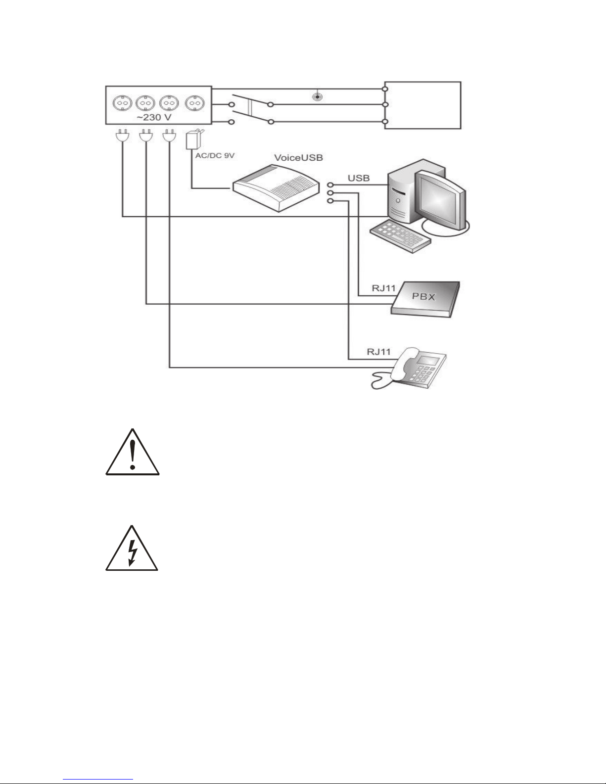
5.3.1 Trunk mode ................................................................................................................................12
5.3.2 Extension mode .............................................................................................................................18
5.4 Connecting VoiceUSB to the PC.........................................................................................................23
5.5 Connection of the power supply ........................................................................................................24
5.6 THE START .........................................................................................................................................24
5.7 Entering the PIN code.........................................................................................................................24
5.7.1 Manual PIN code entering .........................................................................................................25
5.7.2 Automatic PIN code entering....................................................................................................25
6VoiceUSB Service menu.....................................................................................................................................26
6.1 General Parameters ..............................................................................................................................27
6.1.1 Device operating mode control.................................................................................................27
6.1.2 Country selection.........................................................................................................................27
6.1.3 USB Connection Mode...............................................................................................................27
6.1.4 Number dial interval ...................................................................................................................28
6.2 Security parameters...............................................................................................................................28
6.2.1 Changing Service menu password.................................................................................................28
6.2.2 PIN code entering control .........................................................................................................29
6.3 Trunk mode parameters....................................................................................................................30
6.3.1 Caller ID type display..................................................................................................................30
6.3.2 Number prefix..............................................................................................................................30
6.3.3 Polarity reverse.............................................................................................................................31
6.3.4 Call duration indicating signal....................................................................................................31
6.4 Extension mode parameters..................................................................................................................32
6.4.1 DTMF sensitivity in Extension mode ........................................................................................32
6.5 Numbers and prefixes blocking..........................................................................................................32
6.5.1 Prefix blocking .............................................................................................................................32
6.5.2 Number blocking.........................................................................................................................33
6.5.3 Allowed numbers.........................................................................................................................34
6.6 Restoring default settings.....................................................................................................................35
6.6.1 Default settings ............................................................................................................................36
6.7 Table of Parameters ............................................................................................................................37
7ACRONYMS .................................................................................................................................................38
TECHNICAL SUPPORT.....................................................................................................................................38
List of Countries .....................................................................................................................................................39

ATTENTION
Do not rip the device. Do not touch the device if the device
block is broken or its connecting wires are without isolation.
All wireless devices for data transferring may be susceptible to
interference, which could affect performance.
Only qualified personnel may install or repair this product.
The device is not water-resistant. Keep it dry.
The device must be steadily fastened on the mounting place.
Do not mount or serve device during the thunderbolt.
The device requires high 220V voltage.
IMPORTANT NOTES MUST BE READ BEFORE STARTING THE WORK WITH THE
DEVICE!
GENERAL SAFETY REQUIREMENTS
You will avoid dangerous situations and harming of yourself if you will follow to these
recommendations. You have to be familiar with the safety requirements before starting using the
device!
To avoid burning and voltage caused traumas, of the personnel working with device, please
follow these safety requirements.
Installation and technical support of the VoiceUSB device can be
performed only by a qualified personnel or a person who has
enough knowledge about this device and safety requirements.

VoiceUSB device requires 9V 1.12 A constant power supply
source that satisfies all safety requirements listed in EN 60950-1
standard.
The PC and power supply source, to which the device VoiceUSB
is connected, should satisfy LST EN 60950 standard. The device
VoiceUSB can be used on first (Personal Computer) or second
(Notebook) computer safety class.
The PBX station and/or the phone connected to the device must
satisfy all safety requirements listed in EN 60950-1 standad.
To avoid mechanical damages of the device it is recommended to transport the VoiceUSB
device packed in damage-proof pack. While using the device, it should be placed so, that its indication
LEDs would be visible as they inform in which working mode the device is and if it has any working
problems.
For VoiceUSB device‘s network capacity working environment has big influence. If the
device starts working insufficiently only qualified personnel may repair this product. We recommend to
forward it to repair centre or to manufacturers. No exchangeable parts inside of the device.
In the installation place and supply circuits protective devices (bipolar release device)
should be tooled up which will protect from short-circuit and wrong ground installation. The power of
connected device should satisfy power of release device. The interstice between contacts should be no
less than 3mm. Power supply network should be installed near device on easy accessible place.

Picture 1.Connection scheme of VoiceUSB device
VoiceUSB device can be directly connected to phone line.
Disconnect device from power supply before connecting it to the
phone line.
Mounting of the device
Disconnect device from power supply before mounting to avoid
voltage effect!
Device service
If the device starts working insufficiently only qualified personnel may repair this product. We
recommend to forward it to repair centre or to manufacturers. No exchangeable parts inside of the
device.
Electrical
Switch
Board
Personal
Computer
Automatic Shutdown
Device
Wall Outlet
Groudin
g
PHASE
NULL

1ABOUT THE DOCUMENT
In this document VoiceUSB device technical characteristics are presented, also it is
described how to connect VoiceUSB device to other devices and how to configure it..
VoiceUSB device is being continuously improvedworking quality, adding specific requirements
from the clients. Therefore, a Firmware update procedure is created.
2INTRODUCTION
VoiceUSB device is created correspondingly to up-to-date telecommunications and electronic
technologies.
In Trunk mode VoiceUSB emulates the line. Phone calls in GSM network can be received with
the connected to the device analogue phone.
When the device is connected to PBX it emulates external line while being in Trunk mode.
When the device is connected to PBX it allows phone calls to/from any number in PBX to GSM
network and vice versa while being in Extension mode.
VoiceUSB device can work as a GSM modem that can create pathway to Internet, exchange data
using GPRS, CSD data bearers.
It also gives a user exclusive possibility to change parameters of the device with ordinary
telephone using VoiceUSB Service menu or with a connected PC with special VoiceUSB Configuration Tool
software.

3PACKAGE CONTENTS
VoiceUSB device is delivered to the client in cardboard box with all required supplements
necessary for work. Package consists of
!Cardboard box.
!VoiceUSB device.
!USB A "USB mini B connection cable.
!AC/DC power supply adapter.
!CD with User Manual and drivers.
!External GSM antenna.
!Components of mounting.
Note:
the manufacturer does not provide SIM card, which is necessary for
connecting to the GSM network! SIM card can be obtained from your GSM
operator!
If any of the components is missing from your package, please contact manufacturer’s
representative or salesperson.
4TECHNICAL CHARACTERISTCS
4.1 Data Transfer
VoiceUSB device supports the following data bearers used in GSM network. Which data channel
is used depends on your GSM operator and data transfer capacity in chosen GSM network
!GPRS class 10
oFull PBCH support.
oMS class B.
oCoding scheme 1-4.
!Circuit Switched DataUp to 9.6 kbit/s, Transparent/Non-transparent mode
VoiceUSB device also has an incoming number detection function. A ES300778-1/2 standard and
MDMF format is used for it.
4.2 Mechanical characteristics
VoiceUSB device case is made of plastic. External view and measurements of the device are
shown in picture 4.2.1.

Picture 4.2.1. External view and measurements of the device
4.3 Operating characteristics
The device is powered from a 9 V (DC) power supply. The PC to which the VoiceUSB device is
connected must have a USB interface corresponding to USB 1.1 or USB 2.0 standards. Electrical
parameters of the device are shown in Table 4.3.1.
Table 4.3.1. Electrical characteristics of VoiceUSB
Parameter Min Nominal Max Units
Power Supply Voltage +9 +12 +15 V
Average Power consumption - 1.4 7.2 W
Currency Consumption 100 120 800 mA
Operating conditions and weight of the device are shown in Table 4.3.2 .
Table 4.3.2. Operating conditions and weight
Parameter Min Nominal Max Units
Weight 135±10 - g
Operating Temperature -0 - +55 ºC
Storage Temperature -20 - +70 ºC
Note:
If the settings outreach the characteristics given above, the device can be
damaged!
32

4.4 Indication
VoiceUSB has 5 LEDs for device status indication. They are located at the top part of the device.
The indication statuses of the device are described in Table 4.4.1.
Table 4.4.1. Device status description
Status Description
Power LED is on Power supply on
Status blinking Device is preparing for work
Status on Device is ready to work (GSM network is
detected, general configurations are made)
Mode blinking Device is connected to the Internet or calling
Mode on USB interface connected to the device
On/Hook LED on Phone is picked up
Error LED blinking Device is awaiting for PIN code
Error LED on SIM card not found
Status, Mode, On/Hook, Error blinking Wrong PIN code

5
VoiceUSB
PREPARATION TO WORK
Before starting working with VoiceUSB device, antenna must be connected (see chapter 5.1).
Then, insert SIM card and make sure that it is inserted properly.
5.1 Connection of antenna
Antenna mounting place is chosen according to mounting place features. It is recommended to
mount the antenna inside the building. If because of network conditions antenna is to be mounted
outside, it is necessary to set antenna ground and quick-acting security implement against lightning.
Antenna is mounted using the standard SMA connector. Antenna connection is shown in picture 5.1.1.
Picture 5.1.1. Connection of antenna
5.2 Inserting SIM card
SIM card must be inserted as is shown in picture 5.2.1 and make sure that it is inserted properly.
Picture 5.2.1. Inserting SIM card

5.3 Devices connection to
VoiceUSB
Depending on what action the VoiceUSB device must perform, the following connections are to
be made
!Phone
!PBX
!Computer.
Picture 5.3.1 Devices connection to VoiceUSB
VoiceUSB can operate in two modes Trunk and Extension.
In Trunk mode VoiceUSB emulates the line. With connected analogue phone, phone calls can be
made and received through the GSM network. VoiceUSB device supports the number display function.
In Trunk mode VoiceUSB can be connected to PBX. In this case VoiceUSB emulates external
line and is connected to one of the PBX CO sockets. In this mode the phone call forwarding depends
on PBX configuration.
In Extension mode VoiceUSB is connected to PBX Extensions socket. In this case VoiceUSB
instead of emulating the line, loads it. In this mode, the phone call forwarding depends on the user, that
is a phone call to GSM network can be made from any internal number and from GSM network to any
internal number.
5.3.1 Trunk mode
In this mode VoiceUSB device emulates the analogue line. Depending upon needs, phone or PBX
station can be connected to it through a standard RJ11 connector marked as PHONE.
Trunk mode is activated through VoiceUSB Service menu (##1111# 1# 2# 0#) or with
VoiceUSB Configuration Tool.

5.3.1.1 Connecting phone to VoiceUSB (Trunk mode)
Module also generates the voltages necessary for the call. The phone connected to the VoiceUSB
device can make and receive incoming calls from the GSM network. The connection to the device is
shown in picture 5.3.2.
Picture 5.3.2. Phone connection to the VoiceUSB in Trunk mode
5.3.1.1.1 Call examples
To make a phone call, connect the phone to the VoiceUSB, insert the SIM card and plug the
power supply.
Note:
Calling mode may not work in the following situations: a) when
VoiceUSB device is connected to the Internet; b) when Extension mode is activated;
c) when working in Service menu; d) when working with VoiceUSB Configuration
Tool
Wait until the device gets ready for work. Enter PIN code of the SIM card if required.
Phone call from phone to a mobile phone using
Trunk
mode
!Pick up the phone, connected to the VoiceUSB, handset. Dialing tone should be heard.
!Dial the number and wait for the connection. Time period between two different digits can be
no longer than 3 seconds (see chapter 6.1.4.).
!To terminate the call, hung up the phone.
Note:
Making international phone call dial 00, instead of +
Step 1 Step 2

Picture 5.3.3. Phone call from phone to mobile phone using Trunk mode
Phone call from mobile phone to phone using the
Trunk
mode
Dial the number of the SIM card inserted in the VoiceUSB and wait for the signal.
Picture 5.3.4. Phone call from mobile phone to phone using the Trunk mode
5.3.1.2 PBX connection to the VoiceUSB (Trunk mode)
In this mode VoiceUSB, connected to the PBX, emulates external line.
Note:
Before connecting VoiceUSB to PBX, the PBX has to be accordingly configured
VoiceUSB connection to PBX is shown in picture 5.3.5.

Picture 5.3.5 PBX connection to the VoiceUSB
5.3.1.2.1 Phone call examples
In order to make a phone call, connect PBX to VoiceUSB (picture 5.3.5), insert the SIM card and
plug the power supply.
Note:
Calling mode may not work in the following situations: a) when
VoiceUSB device is connected to the Internet; b) when Extension mode is activated;
c) when working in Service menu; d) when working with VoiceUSB Configuration
Tool
Wait until the device prepares for work.
Note:
While using the Trunk mode, the PIN code request for GSM
SIM card must be disabled or automatic PIN code entering should be set in the
Service menu!
Phone call from internal line number to a mobile phone using the
Trunk
mode
Let’s say, you want to make a phone call from the internal line number to a GSM network
(picture 5.3.6).
!Pick up the phone connected to the PBX Extension socket, handset. Dialing tone should be
heard.
!Dial the external line prefix according to the PBX configuration.
!Dial the mobile phone number and wait for the connection.
!To terminate the call, hung up the telephone handset
Step 1 Step 2

Picture 5.3.6. Phone call from internal line number to a mobile phone using the Trunk mode
Phone call from mobile phone to an internal line number using the
Trunk
mode
Let’s say you want to make a phone call from the GSM network to an internal line number
(picture 5.3.7). Dial the number of the SIM card inserted in VoiceUSB. VoiceUSB will detect the
incoming call and will emulate it. The incoming call will be directed to an appropriate internal line
number depending on PBX configuration.
External Line Prefix
0
*

Picture 5.3.7. Phone call from mobile phone to an internal line number using the Trunk mode
5.3.1.3 Trunk mode parameters
All parameters can be changed with Service menu or VoiceUSB Configuration Tool.
Caller ID
The device supports the incoming call ID display function. The incoming number can be shown
on the display of the phone connected to the VoiceUSB device.
Number Prefix
VoiceUSB has a Number Prefix function. When this function is enabled, a prefix will be
automatically added to every dialed number.
Polarity Reverse
When the function is active, polarity reverse will perform when the over party picks up the
phone. Otherwise, the polarity reverse will perform when the over party will pick up the handset of the
phone connected to the VoiceUSB device.
Minute notification
VoiceUSB device has a Minute notification function. When this function is activated, during the
voice call, a short notification beep will be heard each minute.
External Line Prefix
0
*

Prefix blocking
This mode allows to create a blacklist of number prefixes so the user would not be able to make a
call to the number which starts with them. If user dialls a forbidden prefix, VoiceUSB will restart itself.
The prefix list can be formed in Service Meniu or VoiceUSB Configuration Tool.
Number blocking
This mode allows to create a blacklist of numbers so the user would not be able to call them. If
user dialls a forbidden number, VoiceUSB will restart itself. The forbidden number list can be formed in
Service Meniu or VoiceUSB Configuration Tool.
Allowed Numbers
This mode allows to create a list of numbers that will be allowed to use Trunk mode. If caller‘s
number will not match any number from the list, VoicUSB, will reject the call.
Note:
All functions are listed in Service menu or in VoiceUSB
Configuration Tool description.
5.3.2 Extension mode
In this mode a call from GSM network to VoiceUSB module is possible. The module will
commutate with any number in internal or PSTN network. Also it is possible to make a call from any
internal or PSTN number (through PBX) to GSM network.
Extension mode is activated through the Service menu (##1111# 1# 1# 0#) or with VoiceUSB
Configuration Tool.
5.3.2.1 PBX connection to VoiceUSB (Extension mode)
Picture 5.3.8. PBX connection to VoiceUSB
Step 1 Step 2

5.3.2.1.1 Calling examples
In order to make a phone call, connect VoiceUSB to one of the PBX Extensions sockets (picture
5.3.8), insert the SIM card and plug the power supply.
Note:
Calling mode may not work in the following situations: a) when
VoiceUSB device is connected to the Internet; b) when Trunk mode is activated; c)
when working in Service menu; d) when working with VoiceUSB Configuration
Tool
Wait until the device prepares for work.
Note:
While using the Extension mode, the PIN code request for GSM
SIM card must be disabled or automatic PIN code entering should be set in the
Service menu!
Phone call from internal line number to a mobile phone using the
Extension
mode
Let’s say you want to make a phone call from an internal line number to a GSM network (picture
5.3.9).
!Pick up the phone connected to the PBX Extension socket, handset. Dialing tone should be
heard
!Dial the internal VoiceUSB number
!Wait until you hear the dialing tone
!Dial the mobile phone number and wait for the connection.
!To terminate the call, hung up the telephone handset

Picture 5.3.9. Phone call from internal line number to a mobile phone using the Extension mode
Phone call from a mobile phone to internal line number using the
Extension
mode
Let’s say you want to make a phone call from the GSM network to the internal line number
(picture 5.3.10). In your mobile phone dial the number of the SIM card inserted in VoiceUSB. The
device will automatically detect the incoming call and will answer it. Dial the internal line phone
number after the long phone tone signal.

Picture 5.3.10. Phone call from a mobile phone to internal line number using the Extension mode
5.3.2.1.2 Call Through
Extension mode allows you to use Call Through function, which makes calling from mobile to
internal number much easier.
To make a Call Through you just have to dial phone number of a SIM card inserted into
VoiceUSB device, pause sign and internal number.

Each mobile phone has it’s own way to make a pause. Please see below
For a Nokia phone
!Step 1. Dial phone number of a SIM card inserted into VoiceUSB device
!Step 2. Press * 3 times to show ‘p’. (This causes dialing to pause)
!Step 3. Dial internal number
Example. 0037068884p103
For a Siemens or Panasonic phone
!Step 1. Dial phone number of a SIM card inserted into VoiceUSB device
!Step 2. Press and hold ‘0’ to show ‘+’. (This causes dialing to pause)
!Step 3. Dial internal number
Example. 0037068884+103.
For a Motorola or Ericsson phone
!Step 1. Dial phone number of a SIM card inserted into VoiceUSB device
!Step 2. Press and hold * to show ‘p’. (This causes dialing to pause)
!Step 3. Dial internal number
Example. 0037068884p103.
5.3.2.2 Extension mode parameters
All parameters can be changed with VoiceUSB Configuration Tool or through the Service menu of the
connected to the device phone.
DTMF sensitivity
This menu item allows to change number dialing tone signal level in Extension mode. It is
recommended to change it if during the call in Extension mode the device does not react to a dialed
number or reacts to several digits (then the level should be decreased) or if the number is dialed
because of the interference when in reality no number is being dialed (then the level should be
increased).
Prefix blocking
This mode allows to create a blacklist of number prefixes so the user would not be able to make a
call to the number which starts with them. If user dialls a forbidden prefix, VoiceUSB will restart itself.
The prefix list can be formed in Service Meniu or VoiceUSB Configuration Tool.
Number blocking
This mode allows to create a blacklist of numbers so the user would not be able to call them. If
user dialls a forbidden number, VoiceUSB will restart itself. The forbidden number list can be formed in
Service Meniu or VoiceUSB Configuration Tool.
Table of contents