TeMec Drive AZ2 User manual
AZ2
DC MOTOR DRIVE
USER MANUAL
AZ2USER MANUAL
ST.TEC.003.EN Rev. 2.1
2 / 52
Read carefully this manual before using the drive.
TeMec Drive reserves the right to change the information reported in this manual without prior notice
because the product is in continuous evolution.
No part of this manual may be howsoever reproduced without previous consent by TeMec Drive.
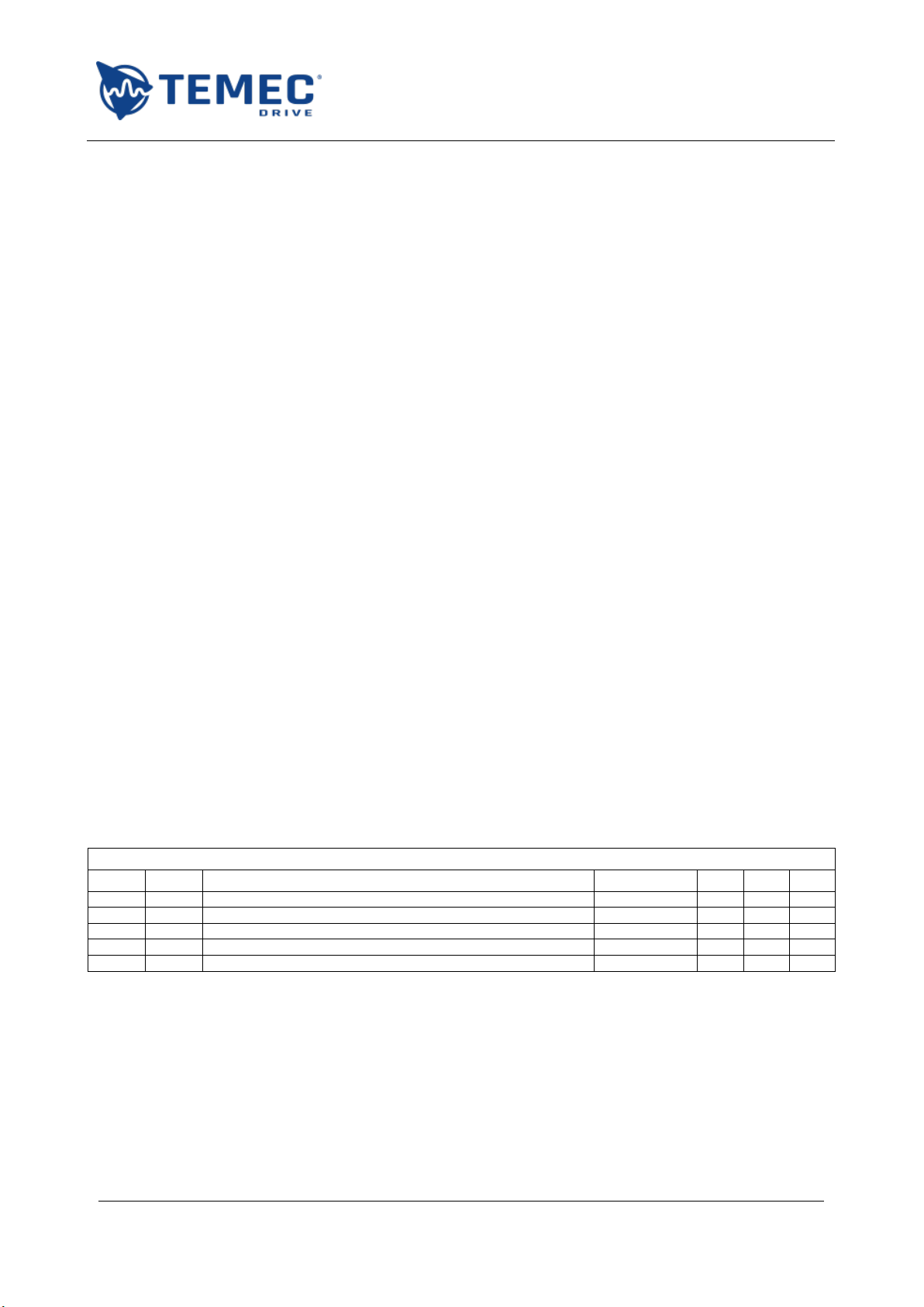
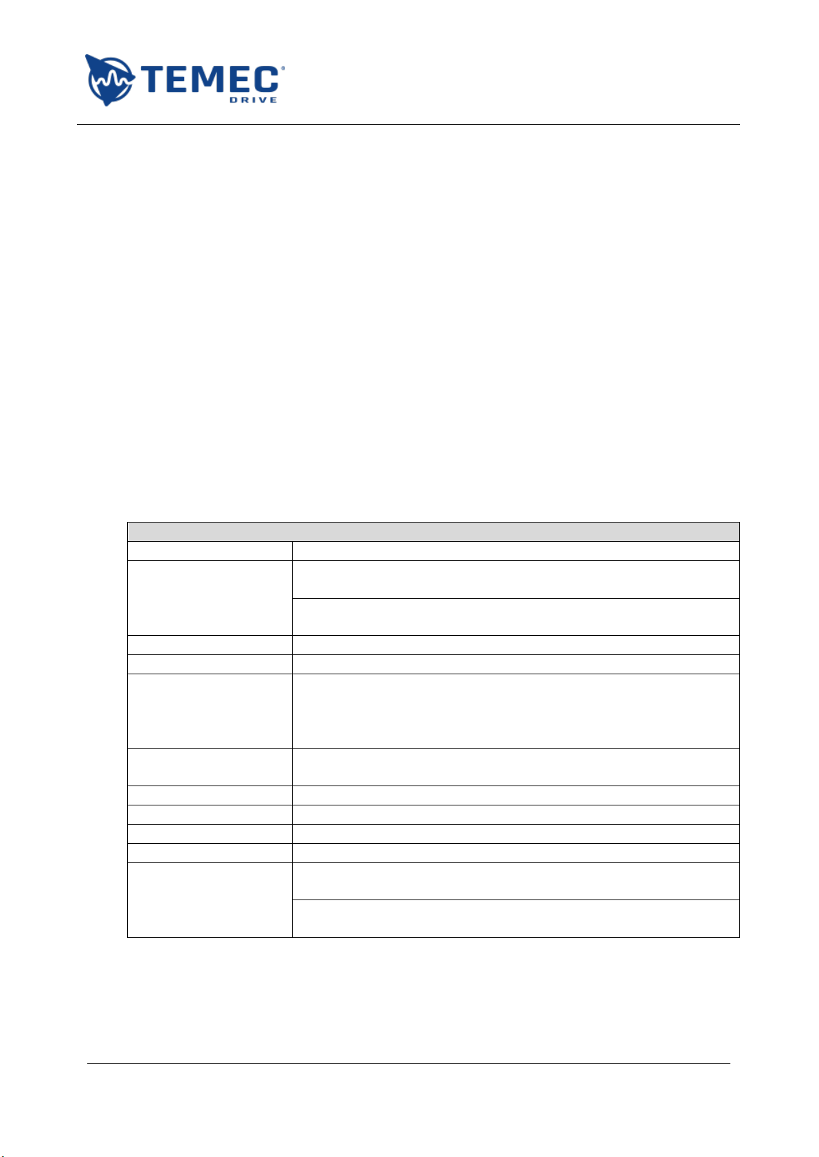
REVISIONS INDEX
Rev.
Par.
Description
Date
R
V
A
0.0
-
First release
04/03/2016
1.0
-
Update. Independent with encoder functionalities added.
01/03/2019
2.1
9
Corrected troubleshooting for yellow error
11/11/2020
RZ
R = Redaction
V = Verification
A = Approval

AZ2USER MANUAL
ST.TEC.003.EN Rev. 2.1
3 / 52
Index
1. SAFETY PRECAUTIONS.....................................................................................................................5
1.1. Operating limits................................................................................................................................. 5
1.2. Handling............................................................................................................................................. 5
1.3. Transportation and installation......................................................................................................... 6
1.4. Wiring ................................................................................................................................................ 7
1.5. Operations......................................................................................................................................... 8
1.6. Modification of advanced parameters.............................................................................................. 8
1.7. Maintenance and inspection............................................................................................................. 9
1.8. Disposal.............................................................................................................................................. 9
1.9. CE conformity and applicable standards........................................................................................... 9
2. GENERAL INFORMATION............................................................................................................... 10
2.1. Technical characteristics.................................................................................................................. 10
2.2. Board overview................................................................................................................................ 11
2.3. Ordering codes ................................................................................................................................ 11
3. INSTALLATION AND WIRINGS........................................................................................................ 12
3.1. Installation environment................................................................................................................. 12
3.2. Mechanical installation.................................................................................................................... 12
3.3. Mechanical drawings....................................................................................................................... 13
3.4. External power supply connections ................................................................................................ 14
4. OPERATION OF TWO INDEPENDENT MOTORS WITHOUT ENCODER................................................ 15
4.1. Connections and commands ........................................................................................................... 15
4.2. Ramps.............................................................................................................................................. 18
4.2.1. Advanced parameters ............................................................................................................. 18
4.3. Current limits................................................................................................................................... 19
4.3.1. Advanced parameters ............................................................................................................. 20
5. OPERATION OF TWO INDEPENDENT MOTORS WITH ENCODER ...................................................... 22
5.1. Connections and commands ........................................................................................................... 22
5.2. Homing function.............................................................................................................................. 25
5.2.1. Advanced parameters ............................................................................................................. 26
5.3. Normal run ...................................................................................................................................... 26
5.3.1. Advanced parameters ............................................................................................................. 27
6. OPERATION OF TWO SYNCHRONIZED MOTORS ............................................................................. 29

AZ2USER MANUAL
ST.TEC.003.EN Rev. 2.1
4 / 52
6.1. Connections and commands ........................................................................................................... 29
6.2. Trimming mode ............................................................................................................................... 30
6.3. Homing function.............................................................................................................................. 30
6.3.1. Advanced parameters ............................................................................................................. 31
6.4. Normal run ...................................................................................................................................... 32
6.4.1. Advanced parameters ............................................................................................................. 33
7. ERRORS AND DIAGNOSTICS........................................................................................................... 35
7.1. Global errors.................................................................................................................................... 35
7.1.1. Advanced parameters ............................................................................................................. 36
7.2. Motor specific errors....................................................................................................................... 37
7.2.1. Advanced parameters ............................................................................................................. 38
8. PARAMETER TABLES ..................................................................................................................... 39
8.1. Digital inputs and outputs ............................................................................................................... 39
8.2. Ramps.............................................................................................................................................. 40
8.3. Current limits................................................................................................................................... 40
8.4. Synchronism - motor 1 and motor 2 ............................................................................................... 43
8.5. Synchronism - global ....................................................................................................................... 45
8.6. Independent with encoder.............................................................................................................. 45
8.7. Global errors.................................................................................................................................... 45
8.8. Motor specific errors....................................................................................................................... 47
9. TROUBLESHOOTING...................................................................................................................... 49
10. MAINTENANCE AND INSPECTION.................................................................................................. 51
11.DISPOSAL ..................................................................................................................................... 51

AZ2USER MANUAL
ST.TEC.003.EN Rev. 2.1
5 / 52
1. SAFETY PRECAUTIONS
Read carefully the following items so that you can safely use the drive avoiding causing injury to the
operators, damaging the mechanic components driven by the drive or other objects in the area.
Make sure you that all warnings are correctly observed.
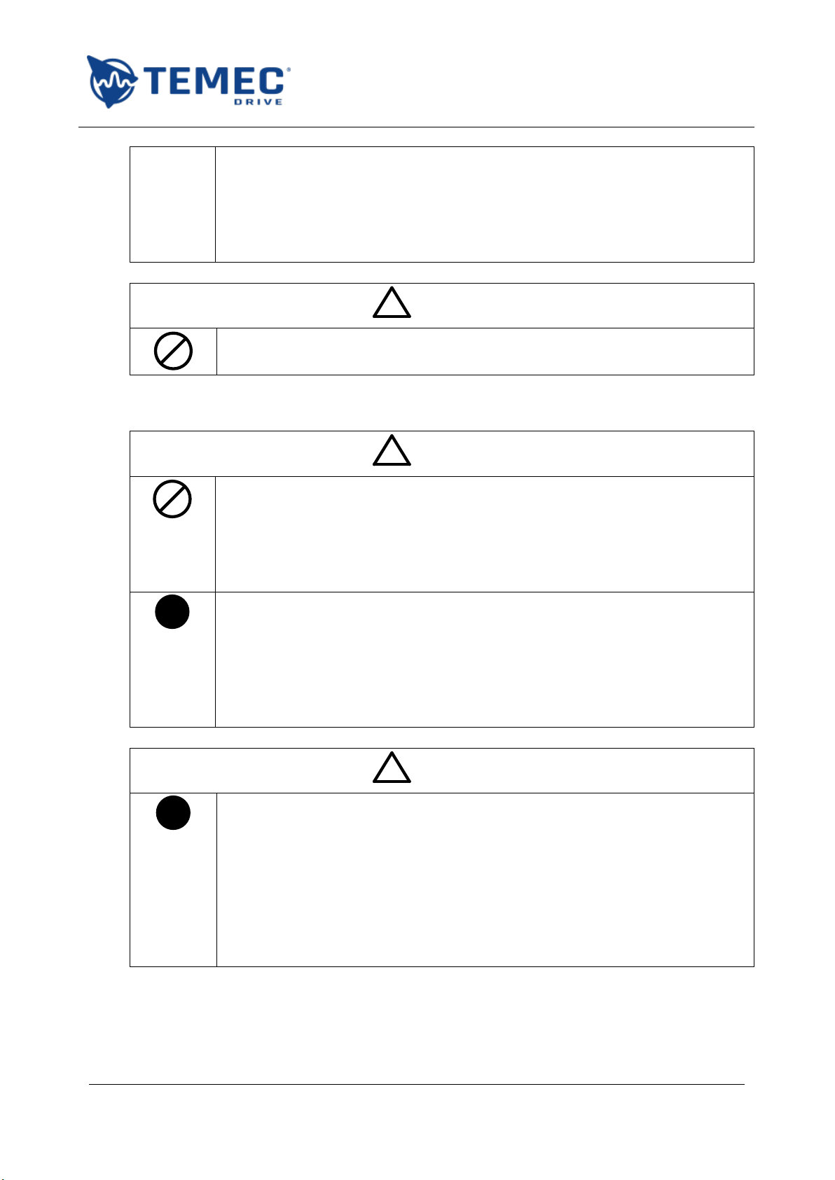
Safety marking legend:
MARKING
Meaning of the marking
!WARNING
Indicates that errors that may lead to death or serious injury.
!CAUTION
Indicates that errors that may lead to injury to people or damage
objects.
MARKING
Meaning of the marking
Prohibition. Do not do it.
!
Obligation. Follow the instruction.
!
Warning.
1.1. Operating limits
This drive is designed for the open loop control of one or two linear actuators driven by direct
current motors for synchronous or independent operation. Do not use for driving other electrical
loads or motor types without first contacting your TeMec Drive distributor.
Use the drive only in industrial application; do not use it where a possible fault can cause serious
injury to human life, like nuclear plants, aviation, safety device, entertainment, medical.
Use the drive only where a possible fault of the drive does not cause serious accidents or
damages or use it only where safety equipment is applicable or a backup circuit device is provided
outside the system.
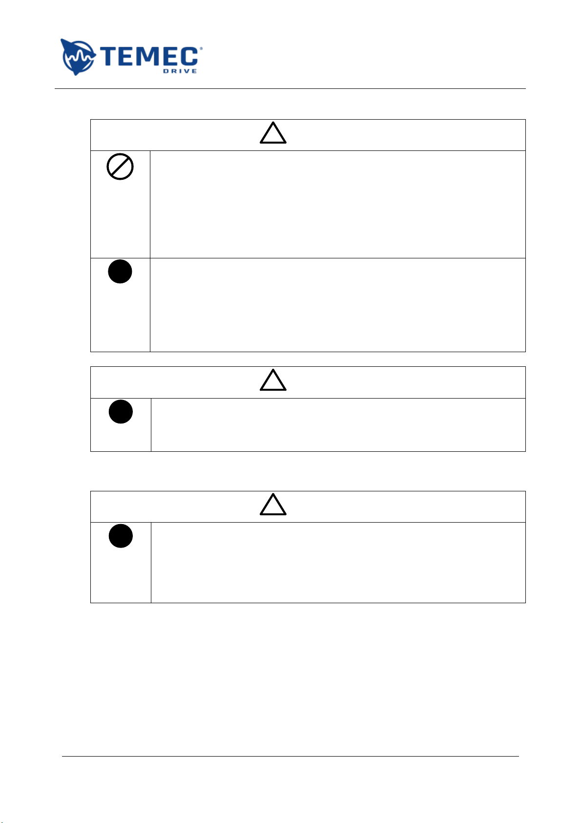
1.2. Handling
!WARNING
Do not disassemble, modify or repair. This can cause electrical shock, fire and
injury.
Do not touch the electronic drive components when power is on. This can result
in electric shock or other injury.
Do not allow water or any other fluid to come in contact with the drive. This can
result in electric shock or fire.
!
Turn on the power only when the drive is closed in a proper insulating cabinet to
avoid electric shock or other injury.
AZ2USER MANUAL
ST.TEC.003.EN Rev. 2.1
6 / 52
If the drive begins to emit smoke, an unusual odour, or unusual sounds,
immediately disconnect the power. Continuous use of the drive in such a state
may cause fire. Call your TeMec Drive distributor for assistance and/or repair.
Always turn the power off if the drive is not used for long time. Leaks, dust and
other material may cause malfunctions and if power is left on with the drive in
that state, it may result in fire.
!CAUTION
Do not touch heatsink fins or discharge / braking resistors. These parts may be
hot and can cause burning if you touch them.
1.3. Transportation and installation
!WARNING
Do not install or operate the drive if it is damaged. This can result in electrical
shock or fire.
Do not place any inflammable objects near the drive. If an accident occurs in
which flame is emitted, this could lead to fire.
Do not install in any location where the drive could come into contact with water
or other fluids. This can result in electric shock or fire.
!
Install the drive being sure that no metal part is in contact with the bottom side
of the board. The contact with the exposed tracks may cause electric shock or
fire.
Operate under the environmental conditions prescribed in this instruction
manual. Operations under any other conditions may result in malfunction.
Install an emergency stop device that fits with system specifications. The drive
alone cannot stop operation immediately, thus resulting in an accident or injury.
!CAUTION
!
When installing make sure that the fixing holes are spaced correctly within the
tolerances indicated in this manual. Otherwise the drive may bend and be
damaged.
Pressing too hard on the screwdriver may irreparably damage the drive.
Always turn the power off when removing the drive from its support. After
wiring is complete, be sure to replace the unit into its case.
If braking is necessary (to hold motor shaft), install a mechanical brake. The
function brake on the drive will not function as a mechanical hold, and if used
for that purpose, injury may result.

AZ2USER MANUAL
ST.TEC.003.EN Rev. 2.1
7 / 52
1.4. Wiring
!WARNING
Do not connect in parallel the two power outputs to increase the total current
that can be imposed on a single motor. This can result in electrical shock or fire.
Do not change encoders’ connections after the successful execution of the first
homing. Any change in one of the two encoders’ connections may lead to
instability in the operation that may cause accidents or injury.
First shut off input power and wait at least 5 minutes before touching terminals
and wires on equipment (MCCB) that is connected to drive power side. Touching
the terminals and wires before that time could result in electric shock.
!
Use a protection diode on the positive terminal of the drive power supply to
avoid damages on the supply circuitry in case of regenerative braking of the
motor. The use of the diode is required in case of parallel connection of more
than one drive or connection of other loads in parallel with the drive.
A qualified expert must do electrical construction work. Connection of input
power by someone who does not have that expert knowledge may result in fire
or electric shock.
Connect output terminals (motor side) correctly. If the polarity is incorrect, the
motor(s) will operate in reverse and that may result in injury.
Do the wiring after installation. If wiring is done prior to installation, that may
result in injury or electric shock.
The following steps must be performed before wiring:
1. turn off all input power;
2. wait at least 5 minutes and check to make sure that the on state LED1 is no
longer lit;
3. use a tester that can measure DC voltage (60V DC or more), and check to
make sure that the voltage to the DC main circuits (across +V and 0V) is 45V
or less. If these steps are not properly performed, the wiring will cause
electric shock.
Tighten the screws on the terminal block to specified torque. If the screws are
not tightened to the specified torque, it may lead to fire.
Check to make sure that the input power voltage is within the limits of the rated
power voltage written on the nameplate, with the tolerance indicated in the
manual. If the input power voltage do not respect these conditions, this may
result in fire.
!CAUTION
Do not attach devices with built-in capacitors (such as noise filters or surge
absorbers) to the outputs (motor side) terminals. This could cause a fire.
!
Use a protection diode or set longer decelerating ramps in case of regenerative
braking. Such phenomenons may cause overvoltages and damages to the
external components that constitute the supply circuitry.
AZ2USER MANUAL
ST.TEC.003.EN Rev. 2.1
8 / 52
1.5. Operations
!WARNING
Do not overload the drive over its capabilities. The use of the drive over its
maximum service factor may cause serious accidents through overheating and
fire.
Do not touch drive terminals when electrical power is going to the drive even if
the motor is stopped. Touching the drive terminals while power is connected to
it may result in electric shock.
Do not touch the drive when the hands are wet. Such action may result in electric
shock.
!
Execute a homing procedure after the power reset, enable parameter SG01 or
use limit switches to avoid overtravel that may cause an accident or injury.
Make sure that operation signals are off before resetting the drive after
malfunction. If the drive is reset before turning off the operating signal, the
motor may restart suddenly, resulting in injury.
If incorrect set, the drive may has some damage or unexpected movement. Be
sure to set the setup menu correctly.
!CAUTION
!
Use a motor that conforms to the specifications of the drive and power supply.
If the motor being used does not conform to those specifications, not only will
the motor not rotate correctly but also it may cause serious accidents through
overheating and fire.
1.6. Modification of advanced parameters
!WARNING
!
Do not modify advanced parameters before reading carefully this manual or
contacting your TeMec Drive distributor. An incorrect set of the parameters can
cause injury or accidents.
Do not disable the soft start function if not strictly necessary; always contact
your TeMec Drive distributor. A possible fault with the drive in such a state may
cause fire.

AZ2USER MANUAL
ST.TEC.003.EN Rev. 2.1
9 / 52
1.7. Maintenance and inspection
!WARNING
Do not replace parts. This could be a cause of electric shock, fire and bodily
injury. To replace parts, call your TeMec Drive distributor.
!
The equipment must be inspected periodically. If the equipment is not inspected
and maintained, errors and malfunctions may not be discovered and that could
result in accidents.
Before inspection, perform the following steps:
1. turn off all input power to the drive;
2. wait at least 5 minutes and check to make sure that the on state LED1 is no longer
lit;
3. use a tester that can measure DC voltages (60V DC or more), and check that the
voltage to the DC main circuits (across +V and 0V) is 45V or less.
Performing an inspection without carrying out these steps first could lead to
electric shock.
1.8. Disposal
!WARNING
!
If you dispose of the drive, have it done by a specialist in industry waste disposal
(*). If you dispose of the drive by yourself, this can result in explosionof capacitor
or produce noxious gases, resulting in injury.
(*) Persons who specialize in the processing of waste and known as "industrial waste
product collectors and transporters" or "industrial waste disposal persons”. Please
observe any applicable law, regulation, rule or ordinance for industrial waste
disposal.
1.9. CE conformity and applicable standards
The AZ2 drive complies with the following standards:
EMC CE-Emission of interference according to EN 61000-6-4: 2007
EMC CE-Immunity to interference according to EN 61000-6-2: 2005
The drive is a component to be used in a second environment (industrial environment) and category
C3, together with specific EMC filters. When used in the first environment (residential / commercial
environment), drives may produce radio-frequency interference dangerous for other equipment: the
user must implement additional filtering measures.
AZ2USER MANUAL
ST.TEC.003.EN Rev. 2.1
10 / 52
2. GENERAL INFORMATION
AZ2is a full electronic motor drive designed for the control of two DC motors in low voltage
applications. The power stage is based on MOS transistor technology, controlled by a pulse width
modulation (PWM). A digital signal processor (DSP) elaborates the control data, generates the output
waveforms and manages the communication interfaces.
The user can exchange data and commands with the drive using the digital I/O and a Modbus
interface. The last one is mainly used for communication with the PC application through which the
user can change parameters, monitor the status of the drive and read diagnostic information. The
use of the Modbus interface in a fieldbus system needs an optional transceiver board, to adapt the
voltages levels from the board to the fieldbus physic level.
The board is also capable to acquire both the output currents, the supply voltage and the board
temperature. More than ten auxiliary I/O are available on the board and can be used for custom
applications or future purposes.
The AZ2drive is designed for the open loop control of linear actuators driven by DC motors but its
use can be extended to any application involving the control of DC motors. For this reason in the
following manual the terms motor and linear actuator, forward/backward and open/close are used
as synonyms.
2.1. Technical characteristics
TECHNICAL DATA
Supply voltage
12 V to 48 V DC, maximum ripple 20%
Output current
Code AZ2048D01000000:
Maximum 10 A / motor, S3 –30% –5 minutes service factor
Code AZ2048D01500000:
Maximum 15 A / motor, S3 –30% –5 minutes service factor
PWM frequency
10 kHz
Quiescent current
50 mA @ 24 V DC supply
Inputs (not isolated)
1.7 –12 V DC ON, 0 –0.7 V DC OFF
8 inputs for commands and limit switches
4 inputs for pulse signals (max 1 kHz)
Pull-up/down (10 kΩ) settable for each input type
Outputs (not isolated)
2 NPN open collector (max 50 mA –24 V DC)
One for general fault and one with programmable function
Output auxiliary voltage
12 V DC, maximum 50 mA
Diagnostic
Blinking codes using a multicolour LED
Operating temperature
-20°C …+60°C
IP grade
IP00
Dimensions and weight
Code AZ2048D01000000:
86 x 72 x 36 mm (LxWxH); 67 g
Code AZ2048D01500000:
86 x 72 x 43 mm (LxWxH); 130 g
Table 1: AZ2technical data
AZ2USER MANUAL
ST.TEC.003.EN Rev. 2.1
11 / 52
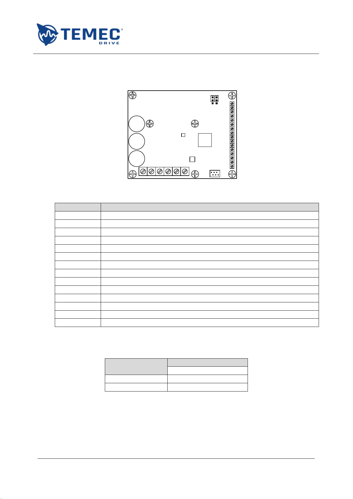
2.2. Board overview
Figure 1 shows the main board components while Table 2 explains the functions associated with
them.
+V 0V M1+ M1- M2+ M2-
1
2
3
4
5
6
7
8
9
10
11
12
13
14
15
16
DSP
LED1
LED2
S1
S1
S1
S1
S2 S2
S3
X1
X2
X3
J2J1
Figure 1: main board components
Component
Function
X1
Power terminal for power supply and motor output connections
X2:1 - X2:8
Signal terminals for inputs
X2:9 - X2:12
Signal terminals for pulse inputs
X2:13
Fault output
X2:14
Configurable output
X2:15
Auxiliary voltage GND and inputs GND
X2:16
Auxiliary voltage +12 V
X3
Connector for communication with PC application or fieldbus interface
J1
Jumper for inputs 1-8 pull-up/down configuration
J2
Jumper for inputs 9-12 pull-up/down configuration
LED1
DSP red LED
LED2
Diagnostic red/green/blue (RGB) LED
S1
Holes for mounting screws
S2
Holes for heat sink mounting screws
Table 2: main components
2.3. Ordering codes
The following table reports the ordering codes:
Code
Options
Output current (per motor)
AZ2048D01000000
10 A
AZ2048D01500000
15 A
Figure 2: ordering codes

AZ2USER MANUAL
ST.TEC.003.EN Rev. 2.1
12 / 52
3. INSTALLATION AND WIRINGS
!
Read carefully the safety precautions reported in 1.3 and 1.4 before installing the drive!
Follow the instruction reported below to install the drive and integrate it into your system.
3.1. Installation environment
Remember that the drive is an electronic device; check carefully that the installation environment is
appropriate:
do not install in any location with high temperature, high humidity, moisture condensation and
freezing;
avoid installing location where there is the possibility of exposition to water, large amounts of
dust, metallic fragments or corrosive gases;
operate in areas where the temperature is within the limit temperatures reported in Table 1;
do not install in any location that can be subject to large amounts of vibrations.
3.2. Mechanical installation
Install the drive being sure that no metal part is in contact with the bottom side of the board.
The contact with the exposed tracks may cause electric shock or fire.
With reference to Figure 1 and Table 2, use S1 mounting holes for the mechanical installation.
Install the drive in vertical position, with the power terminal on the bottom side and so that the
fins of the optional heat sink result in vertical position.
When installing the drive, leave at least the distances shown in Figure 3 so that the wiring can be
made easily and the drive can dissipate the heat generated during the operation.
In case of multiple installations align the drives horizontally, leaving at least the distances shown
in Figure 3.
AZ2AZ2
5 cm
5 cm
5 cm
3
cm
Figure 3: minimum distances for mechanical installation
AZ2USER MANUAL
ST.TEC.003.EN Rev. 2.1
13 / 52
When wiring the drive use the following tightening torques for the terminal blocks:
Terminal block
Tightening torque [Nm]
Minimum
Maximum
X1 –POWER
0.5
0.6
X2 –Signals
0.22
0.25
Table 3: recommended tightening torques
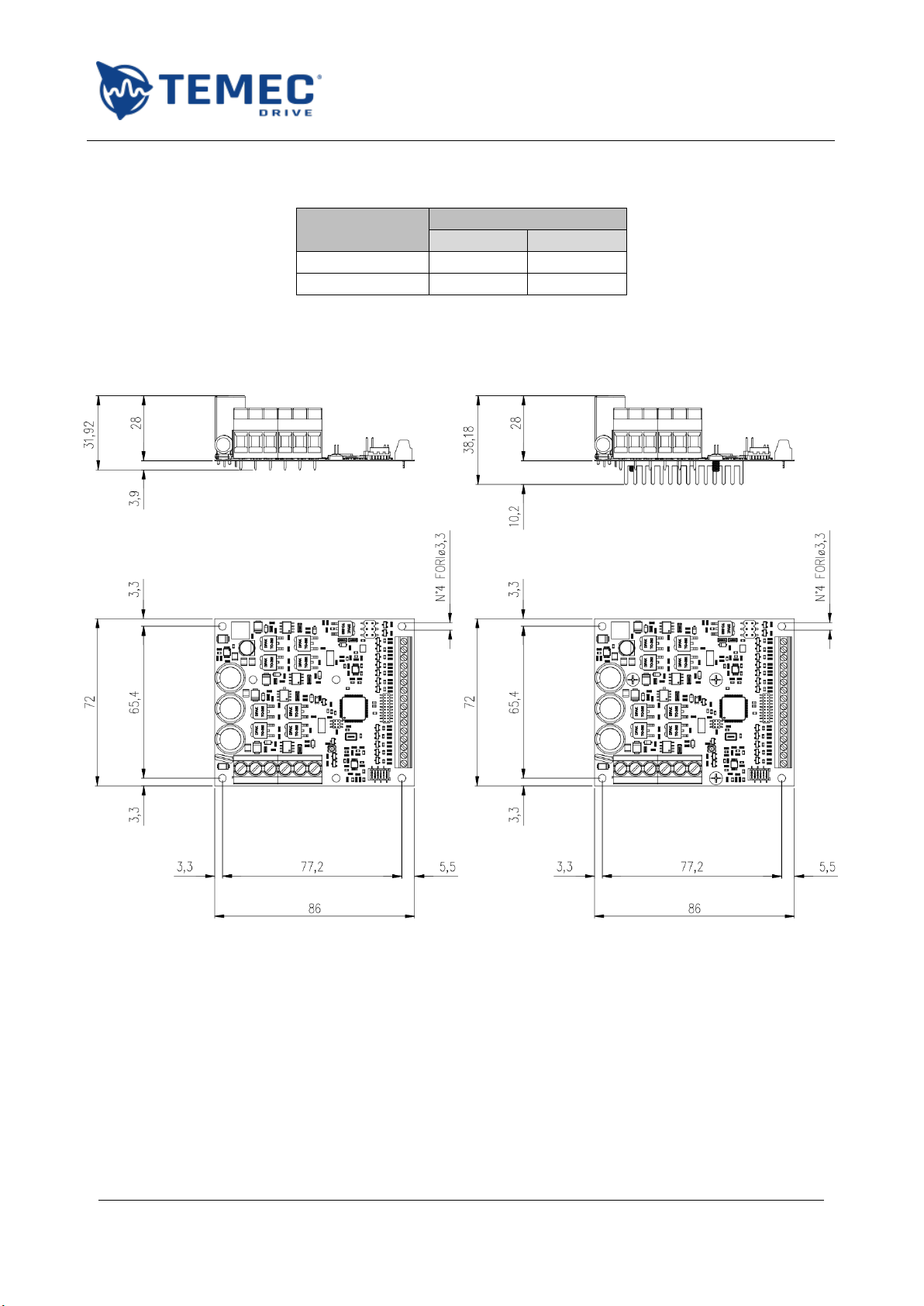
3.3. Mechanical drawings
All quotes are expressed in millimetres:
Figure 4: AZ2048D01000000 dimensions in mm
Figure 5: AZ2048D01500000 dimensions in mm
AZ2USER MANUAL
ST.TEC.003.EN Rev. 2.1
14 / 52
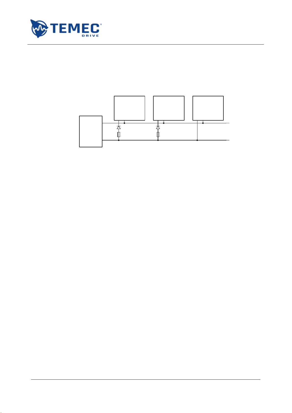
3.4. External power supply connections
It is strongly recommended to use a protection diode on the positive terminal of the drive power
supply to avoid damages on the supply circuitry in case of regenerative braking of the motor. The use
of the diode is required in case of parallel connection of more than one AZ2or connection of other
loads in parallel with the drive, as shown in Figure 6:
AZ2
+V 0V
AZ2
+V 0V
Generic
Load
DC
POWER
SUPPLY+
-
Figure 6: parallel connection of multiple drives
An example of diode that can be used is Infineon IDP30E60, adequately dissipated.
For the protection of the drive use a 25 A time delay fuse for AZ2048D01000000 or 35 A for
AZ2048D01500000.
AZ2USER MANUAL
ST.TEC.003.EN Rev. 2.1
15 / 52
4. OPERATION OF TWO INDEPENDENT MOTORS WITHOUT ENCODER
!
Read carefully the safety precautions reported in 1.5 before operating the drive!
In this operation mode, the drive can independently control the movement of two motors, by
applying on them the desired voltage and following the desired ramps, set by the user. The
movement stops when the relative limit switch signal goes high, when the current limit is achieved,
when the command is released or the STOP signal goes high.
All the parameters areset independently for both motors and for the opening and closing movement.
When the drive is not applying voltage to the motor, the terminals are short-circuited to ground.
4.1. Connections and commands
!
Read carefully the safety precautions reported in 1.4 before wiring the drive!
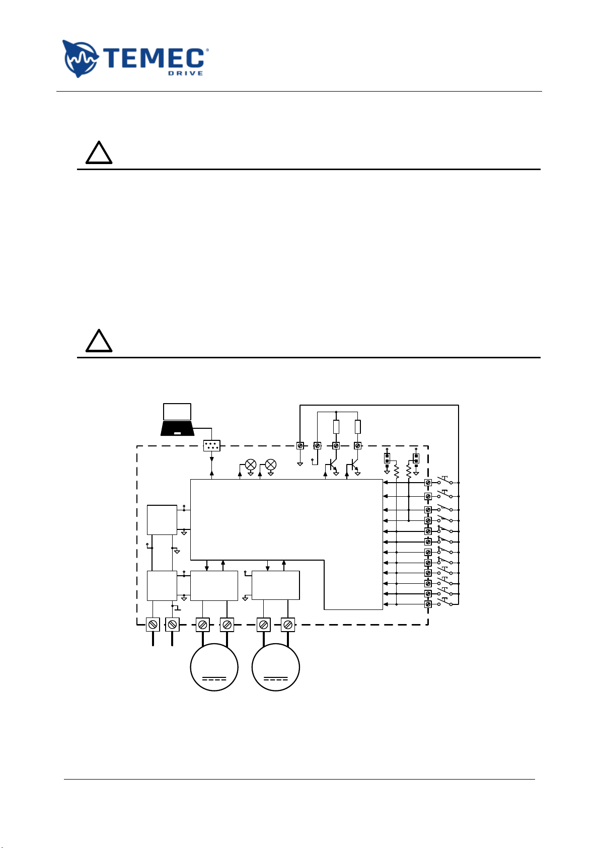
Below is a connection scheme showing all possible commands and devices that can be connected to
the board:
M
Power stage
&
Current sense
M
Power stage
&
Current sense
Switching
power
supply
12 V
DC
regulator
3.3 V
+V
3.3V
12V
12V
10kΩ
+
12V
12-48V DC
RED RGB
Modbus
interface
Inputs
Diagnostics
Motor
Drive
M1+ M1- M2+ M2-
1
2
3
4
5
6
7
12
1615
0V
13 14 J2
12V
OPEN-1
CLOSE-1
OPEN-2
CLOSE-2
OP-SW-1
CL-SW-1
OP-SW-2
STOP-2
Fault 11 STOP-1
8CL-SW-2
9INT-SW-1
10 INT-SW-2
10kΩ
+
J1
DSP
Figure 7: connection scheme example in independent mode

AZ2USER MANUAL
ST.TEC.003.EN Rev. 2.1
16 / 52
For each of the two motors:
Label
Function
OPEN
Open / forward command
CLOSE
Close / backward command
OP-SW
Open limit switch
CL-SW
Close limit switch
INT-SW
Intermediate switch
STOP
Stop command (errors reset)
Table 4: legend of external devices in independent operating mode
The user can set for every input from 01 to 12:
-the reversed logic working mode; set this bit following Table 5:
Normally
open contact
Normally
closed contact
Pull-up
resistor
Enable
reverse logic
Disable
reverse logic
Pull-down
resistor
Disable
reverse logic
Enable reverse
logic
Table 5: instructions for setting the reverse logic input mode
-a delay for the OFF to ON transition;
-a delay for the ON to OFF transition.
For example, digital input 1 parameters are (see 8.1 for the complete list):
Label
Function
Range
Default value
DI00
Reverse input 01 logic
ON / OFF
ON
DI01
Input 01 turn on delay
5 –500 [ms]
10
DI02
Input 01 turn off delay
5 –500 [ms]
10
Table 6: example of digital input parameters
The commands are configured as hold-to-run but can also work in one-press mode changing the
following parameter:
Label
Function
Range
Default value
DI36
Sets inputs in one-press mode
ON / OFF
OFF
Table 7: input mode parameter
The function of the digital output at terminal X2:14 can be set using this parameter:
Label
Function
Range
Default value
DI37
Sets function of output X2:14
See below
General Fault
Table 8: parameter for digital output 2 setting
The possible information that can be sent to OUT2 are:
-motor 1 or 2 Fault;
-motor 1 or 2 Open Limit Switch;
-motor 1 or 2 Close Limit Switch;
-motor 1 or 2 Intermediate Limit Switch;
-motor 1 or 2 Current Open Limit Switch;
-motor 1 or 2 Current Close Limit Switch;
-motor 1 or 2 Electronic Open Limit;

AZ2USER MANUAL
ST.TEC.003.EN Rev. 2.1
17 / 52
-motor 1 or 2 Electronic Close Limit;
-motor 1 or 2 Open Inrush Overcurrent;
-motor 1 or 2 Open Overcurrent;
-motor 1 or 2 Close Inrush Overcurrent;
-motor 1 or 2 Close Overcurrent;
-motor 1 or 2 Encoder disconnected;
-motor 1 or 2 Open Limit Loss;
-motor 1 or 2 Close Limit Loss;
-general Fault;
-power supply overvoltage;
-power supply under-voltage;
-board over-temperature;
-synchronism error.
AZ2USER MANUAL
ST.TEC.003.EN Rev. 2.1
18 / 52
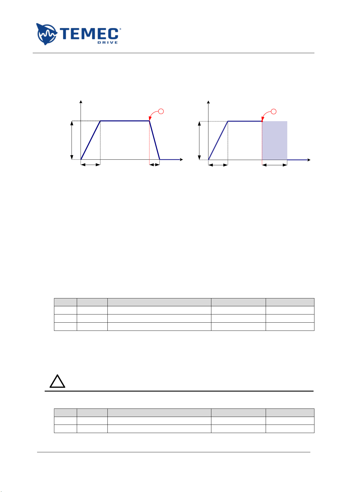
4.2. Ramps
The following figures show how the drive applies the voltage to the motors. The example is the
acceleration and deceleration ramp for motor 1 during the opening movement with two different
stops:
V
t
V
t
M101 M102
M100
!!
High
impedance
M101 M106
M100
Figure 8: ramp waveform example in case of normal stop (left) and overcurrent (right)
In both cases the full voltage is applied gradually, following a ramp long M101 ms.
In the first case (Figure 8 - left) the motor stops because the drive reduces the voltage until 0 V, in
M102 ms. Excluding errors, this happens if:
the command is released;
the STOP command is pressed;
the limit switch is engaged.
When an overcurrent is detected the drive behaviour follows Figure 8 - right: the motor terminals
are disconnected from the power stage (no voltage applied) for M106 = 500 ms and the stop is
achieved by inertia.
The ramps applied to the motors are set using three parameters (see 8.2 for the complete list):
Label
Output
Function
Range
Default value
M100
Motor 1
Open voltage
10 –48 [V]
24
M101
Motor 1
Open acceleration ramp
100 –3000 [ms]
500
M102
Motor 1
Open deceleration ramp
100 –3000 [ms]
500
Table 9: example of ramp parameters
The user can set different ramps for the two motor and for each direction.
4.2.1.ADVANCED PARAMETERS
!
Read carefully the safety precautions reported in 1.6 before modifying any of the
advanced parameters!
In advanced mode the user can modify this further parameters:
Label
Output
Function
Range
Default value
M106
Motor 1
Motor 1 inertial braking time
500 –3000 [ms]
500
M206
Motor 2
Motor 2 inertial braking time
500 –3000 [ms]
500
AZ2USER MANUAL
ST.TEC.003.EN Rev. 2.1
19 / 52
Table 10: ramps advanced parameters
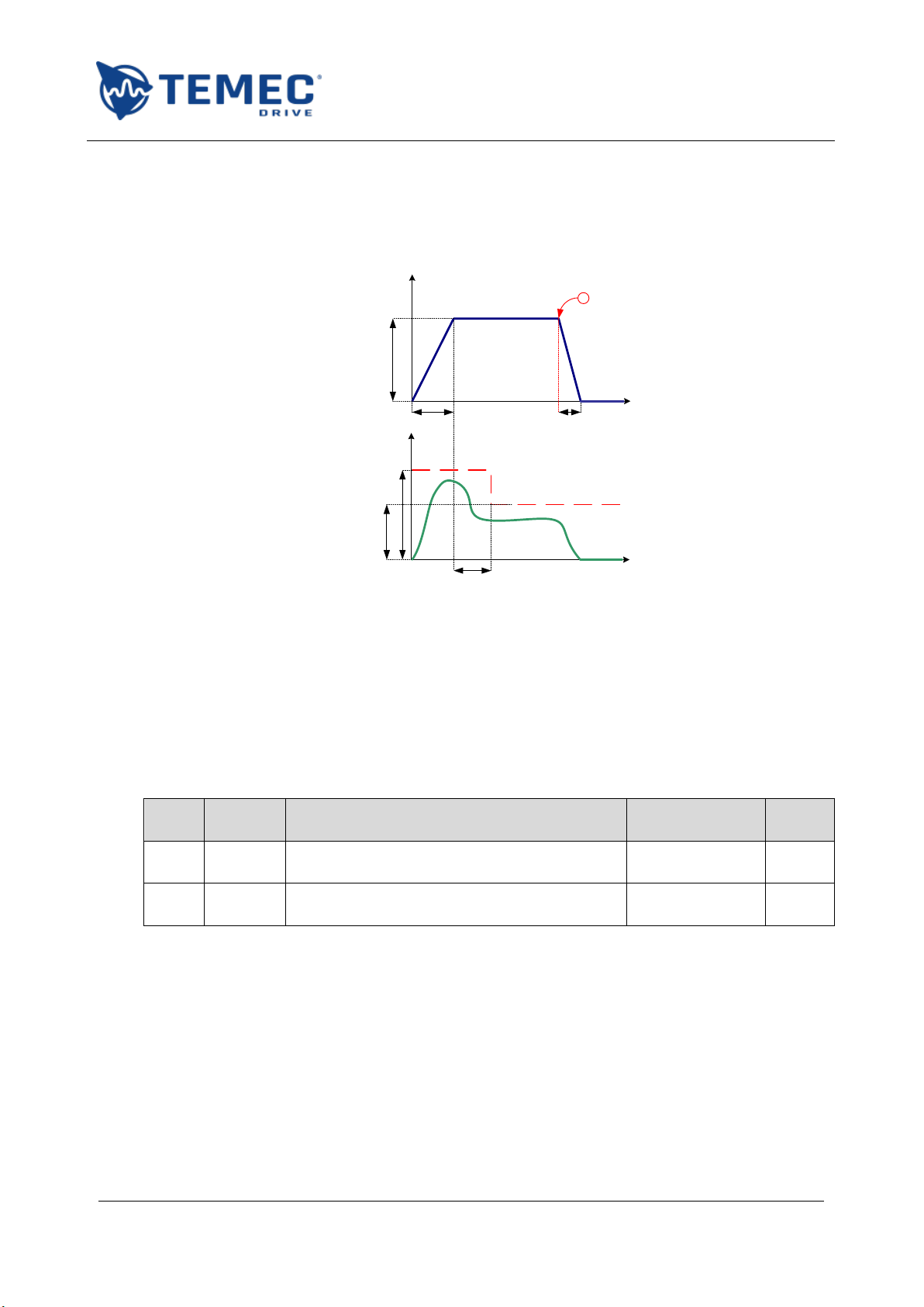
4.3. Current limits
The drive monitors the current absorption during all the motor movement using two thresholds, one
for the start phase and the second during the rest of the run as shown in this Figure 9:
I
t
C106
C102
C108
V
t
M101 M102
M100
!
Figure 9: current monitoring parameters
The first threshold is used for a time given by the sum of M101 and C106 = 1 s. The user can set the
nominal current threshold C108, while the inrush one C102 is calculated as 2 times the first value.
Either the drive can go in block state or not when the current limit is exceeded, depending on the
user choice. If the block is disabled (C107 = OFF), the drive will read the overcurrent as a limit switch
permitting only the movement in the opposite direction.
The parameters below configure the current limit functions for the opening movement of motor 1
(see 8.3 for the complete list):
Label
Output
Function
Range
Default
value
C107
Motor 1
Enables the block in case of overcurrent during
opening
ON / OFF
ON
C108
Motor 1
High threshold of nominal current control
during opening
1 –11 [A]
10
Table 11: example of current limit parameters
The user can set different current limits for the two motor and for each direction.
AZ2USER MANUAL
ST.TEC.003.EN Rev. 2.1
20 / 52
4.3.1.ADVANCED PARAMETERS
!
Read carefully the safety precautions reported in 1.6 before modifying any of the
advanced parameters!
In advanced mode, the user can configure independently the two functions of current monitoring for
inrush and normal run.
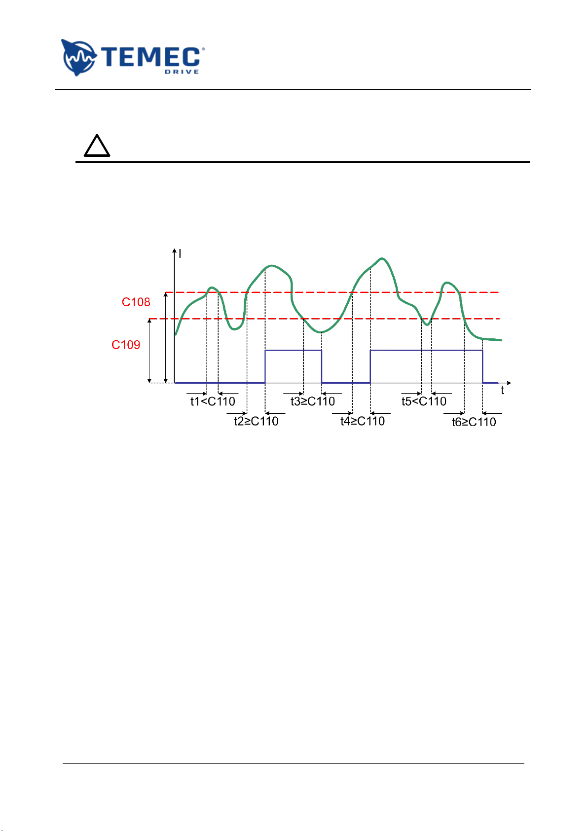
The Figure 10 explains the meaning of the parameters and is applicable to all the monitoring function
of analog and digital quantities; in particular, the parameters shown below are related to the
monitoring of motor 1 nominal current during opening:
Figure 10: example of analog quantity monitoring
The green trace is an example of controlled quantity (i.e. the current), in red there are the two
threshold and in blue the result of the check (high current over the limit).
The check is positive if the controlled quantity exceeds the high threshold for more than C110 ms (t2
and t4but not t1). The quantity returns into the limits (blue trace 0) if it goes down the lower
threshold for more than C110 ms (t3and t6but not t5).
Other changeable parameters are the ones that enable the soft start function (for example C100).
Table of contents
Other TeMec Drive DC Drive manuals

Popular DC Drive manuals by other brands


Invertek Drives
Invertek Drives OPTIDRIVE E3 user manual

Danfoss
Danfoss VLT AutomationDrive FC 300 Series Programming guide

FALK
FALK Ultramite UB Installation & maintenance instructions

Minarik
Minarik RG5500U user manual

KB Electronics
KB Electronics KBWS-12 Installation and operating instructions

ABB
ABB ACS355 series Quick installation and start-up guide


