TeMec Drive AZ3s User manual

TeMec Drive Srl
Via Beretta,1
42024 Castelnovo di Sotto (RE)
Phone +39 0522.68.30.42
Fax +39 0522.68.81.31
P.I. 02614410351

AZ3s USER MANUAL
ST.TEC.054
2 / 60
Indice
1. SAFETY PRECAUTIONS.....................................................................................................................6
1.1. Operating limits................................................................................................................................. 6
1.2. Handling............................................................................................................................................. 7
1.3. Transportation and installation......................................................................................................... 8
1.4. Wiring ................................................................................................................................................ 9
1.5. Operations....................................................................................................................................... 10
1.6. Modification of parameters ............................................................................................................ 10
1.7. Maintenance and inspection........................................................................................................... 11
1.8. Disposal............................................................................................................................................ 11
2. GENERAL INFORMATION............................................................................................................... 12
2.1. Full specifications ............................................................................................................................ 12
3. INSTALLATION AND WIRINGS........................................................................................................ 13
3.1. Installation environment................................................................................................................. 13
3.2. Mechanical installation.................................................................................................................... 13
3.3. Mechanical drawings....................................................................................................................... 13
3.4. Electrical connections...................................................................................................................... 14
3.4.1. X1 –Power............................................................................................................................... 15
3.4.2. X2 connector............................................................................................................................ 16
3.4.3. X3 connector............................................................................................................................ 17
3.4.4. How to connect ....................................................................................................................... 18
4. DRIVE CONFIGURATIONS .............................................................................................................. 22
4.1. Drive data ........................................................................................................................................ 23
4.1.1. parameters .............................................................................................................................. 23
4.1.2. Configurations ......................................................................................................................... 23
4.2. Motor data....................................................................................................................................... 24
4.2.1. Parameters .............................................................................................................................. 24
4.2.2. Configurations ......................................................................................................................... 24
4.3. Factors ............................................................................................................................................. 26
4.3.1. Parameters .............................................................................................................................. 26
4.3.2. Configurations ......................................................................................................................... 26
4.4. Analogic set point............................................................................................................................ 29
4.4.1. Parameters .............................................................................................................................. 29

AZ3s USER MANUAL
ST.TEC.054
3 / 60
4.4.2. Configurations ......................................................................................................................... 29
4.5. Digital commands............................................................................................................................ 31
4.5.1. Parameters .............................................................................................................................. 31
4.5.2. Configurations ......................................................................................................................... 32
4.6. Outputs feedback ............................................................................................................................ 33
4.6.1. Parameters .............................................................................................................................. 33
4.6.2. Configurations ......................................................................................................................... 33
4.7. Electromechanical brake ................................................................................................................. 34
4.7.1. Parameters .............................................................................................................................. 34
4.7.2. Configuration........................................................................................................................... 34
4.8. Start-up option ................................................................................................................................ 36
4.8.1. Parameters .............................................................................................................................. 36
4.8.2. Configuration........................................................................................................................... 36
4.9. Braking behaviour............................................................................................................................ 37
4.9.1. Parameters .............................................................................................................................. 37
4.9.2. Configurations ......................................................................................................................... 37
4.10. Emulated encoder ....................................................................................................................... 38
4.10.1. Parameters .............................................................................................................................. 38
4.10.2. Configurations ......................................................................................................................... 38
4.11. Motor thermistor......................................................................................................................... 39
4.11.1. Parameters .............................................................................................................................. 39
4.11.2. Configurations ......................................................................................................................... 39
4.12. Torque limit ................................................................................................................................. 39
4.12.1. Parameters .............................................................................................................................. 39
4.12.2. Configurations ......................................................................................................................... 39
5. OPERATING MODES...................................................................................................................... 40
5.1. Profile velocity mode....................................................................................................................... 40
5.1.1. Parameters .............................................................................................................................. 40
5.1.2. Configuration........................................................................................................................... 40
5.2. Profile position mode ...................................................................................................................... 42
5.2.1. Parameters .............................................................................................................................. 42
5.2.2. Configurations ......................................................................................................................... 42
5.3. Profile torque mode ........................................................................................................................ 44

AZ3s USER MANUAL
ST.TEC.054
4 / 60
5.3.1. Parameters .............................................................................................................................. 44
5.3.2. Configurations ......................................................................................................................... 44
5.4. Drive commands.............................................................................................................................. 46
5.4.1. Parameters .............................................................................................................................. 46
5.4.2. Configurations ......................................................................................................................... 46
5.5. PID tuning ........................................................................................................................................ 48
6. PARAMETERS TABLE ..................................................................................................................... 49
6.1. Holding registers.............................................................................................................................. 49
6.2. Input registers.................................................................................................................................. 53
6.3. Coils ................................................................................................................................................. 54
7. ERRORS AND DIAGNOSTICS........................................................................................................... 55
7.1. Parameters ...................................................................................................................................... 55
7.2. Diagnostic ........................................................................................................................................ 56
8. TROUBLESHOOTING...................................................................................................................... 57
8.1. Parameters ...................................................................................................................................... 57
8.2. Problem solving ............................................................................................................................... 57
9. MAINTENANCE AND INSPECTION.................................................................................................. 59
10. DISPOSAL ..................................................................................................................................... 59

AZ3s USER MANUAL
ST.TEC.054
5 / 60
INDICE DELLE REVISIONI
Rev.
Par.
Descrizione della modifica
Data
R
V
A
0.1
-
Draft
22/07/2020
mb
Read carefully this manual before using the drive.
TeMec Drive reserves the right to change the information reported in this manual without prior
notice because the product is in continuous evolution.
No part of this manual may be howsoever reproduced without previous consent by TeMec
Drive.

AZ3s USER MANUAL
ST.TEC.054
6 / 60
1. SAFETY PRECAUTIONS
Read carefully the following items so that you can safely use the drive avoiding causing injury to the
operators, damaging the mechanic components driven by the drive or other objects in the area.
Make sure you that all warnings are correctly observed.
1.1. Operating limits
Use the drive only in industrial application; do not use it where a possible fault can cause serious
injury to human life, like nuclear plants, aviation, safety device, entertainment and medical.
Use the drive only where a possible fault of the drive does not cause serious accidents or
damages or use it only where safety equipment is applicable or a backup circuit device is
provided outside the system.
MARKING
Meaning of the marking
Prohibition. Do not do it.
Obligation. Follow the instruction.
Warning.

AZ3s USER MANUAL
ST.TEC.054
7 / 60
1.2. Handling
WARNING
Do not disassemble, modify or repair. This can cause electrical shock, fire and
injury.
Do not touch the electronic drive components when power is on. This can result
in electric shock or other injury.
Do not allow water or any other fluid to come in contact with the drive. This can
result in electric shock or fire.
Turn on the power only when the drive is closed in a proper insulating cabinet to
avoid electric shock or other injury.
If the drive begins to emit smoke, an unusual odour, or unusual sounds,
immediately disconnect the power. Continuous use of the drive in such a state
may cause fire. Call your TeMec Drive distributor for assistance and/or repair.
Always turn the power off if the drive is not used for long time. Leaks, dust and
other material may cause malfunctions and if power is left on with the drive in
that state, it may result in fire.
CAUTION
Do not touch heatsink fins or discharge / braking resistors. These parts may be
hot and can cause burning if you touch them.
AZ3s USER MANUAL
ST.TEC.054
8 / 60
1.3. Transportation and installation
WARNING
Do not install or operate the drive if it is damaged. This can result in electrical
shock or fire.
Do not place any inflammable objects near the drive. If an accident occurs in
which flame is emitted, this could lead to fire.
Do not install in any location where the drive could come into contact with water
or other fluids. This can result in electric shock or fire.
Operate under the environmental conditions prescribed in this instruction
manual. Operations under any other conditions may result in malfunction.
Install an emergency stop device that fits with system specifications. The drive
alone cannot stop operation immediately, thus resulting in an accident or injury.
CAUTION
Always turn the power off when removing the drive from its support.

AZ3s USER MANUAL
ST.TEC.054
9 / 60
1.4. Wiring
WARNING
First shut off input power and wait at least 5 minutes before touching terminals
and wires on equipment that is connected to drive power side. Touching the
terminals and wires before that time could result in electrical shock.
A qualified expert must do electrical construction work. Connection of input
power by someone who does not have that expert knowledge may result in fire
or electric shock.
Connect output terminals (motor side) correctly. Incorrect connections may
result in injury or electric shock.
The following steps must be performed before wiring:
oTurn off all input power.
oWait at least 5 minutes and check to make sure that the on state LED is no
longer lit.
oUse a tester that can measure DC voltage (60 V DC or more) and check to
make sure that the voltage to the DC main circuits (across +VDC and -VDC)
is 45 V or less. If these steps are not properly performed, the wiring will
cause electrical shock.
Check to make sure that the input power voltage is within the limits of the rated
power voltage indicated on the manual. If the input power voltage do not
respect these conditions, this may result in fire.
CAUTION
Do not attach devices with built-in capacitors (such as noise filters or surge
absorbers) to the outputs (motor side) terminals. This could cause a fire
AZ3s USER MANUAL
ST.TEC.054
10 / 60
1.5. Operations
1.6. Modification of parameters
WARNING
Do not overload the drive over its capabilities. The use of the drive over its
maximum service factor may cause serious accidents through overheating and
fire.
Do not touch terminals when electrical power is going to the drive even if the
motor is stopped. Touching the drive terminal while power is connected to it
may result in electrical shock.
Do not touch the drive when the hands are wet. Such action may result in
electric shock.
If parameters are set incorrectly, the drive may have some damage or
unexpected movement. Be sure to set the drive parameters correctly.
CAUTION
Use a motor that conforms to the specifications of the drive and power supply. If
the motor being used does not conform to those specifications, not only will the
motor not rotate correctly but also it may cause serious accidents through
overheating and fire.
WARNING
Do not modify parameters before reading carefully this manual. An incorrect set
of the parameters can cause injury or accidents.
AZ3s USER MANUAL
ST.TEC.054
11 / 60
1.7. Maintenance and inspection
1.8. Disposal
WARNING
Do not replace parts. This could be cause of electric shock, fire and bodily injury.
To replace parts, call your TeMec drive distributor.
The equipment must be inspected periodically. If the equipment is not inspected
and maintained, errors and malfunctions may not be discovered and that could
result in accidents.
Before inspection performs the following steps
oTurn off all input power.
oWait at least 5 minutes and check to make sure that the on state LED is no
longer lit.
oUse a tester that can measure DC voltage (60 V DC or more) and check to
make sure that the voltage to the DC main circuits (across +VDC and -VDC)
is 45 V or less. Performing an inspection without carrying out these steps
first could lead to electric shock.
WARNING
If you dispose of the drive, have it done by a specialist in industry waste
disposal (*). If you dispose of the drive by yourself, this can result in explosion
of capacitor or produce noxious gases, resulting in injury.
(*) Persons who specialize in the processing of waste and known as "industrial
waste product collectors and transporters" or "industrial waste disposal persons”.
Please observe any applicable law, regulation, rule or ordinance for industrial
waste disposal.

AZ3s USER MANUAL
ST.TEC.054
12 / 60
2. GENERAL INFORMATION
AZ3s is an extra-low voltage drive designed for the control of AC/DC brushless motors and DC motors.
The high versatility of this product is demonstrated by the position feedbacks available (Hall,
incremental encoder), the different kind of inputs (analog and digital) and outputs (digital, power
PWM) and the communication interfaces (CAN, Modbus); furthermore it is available in both
integrated and stand-alone versions. The drive can also manage an electromechanical brake or a
braking resistor without relay/contactor.
The AZ3s manual is intended to be used with TeMec Interface manual and Modbus RTU AZ3s manual.
2.1. Full specifications
FULL SPECIFICATIONS
POWER STAGE
Supply voltage
24 V to 48 V DC (maximum limits 20 V to 55 V DC)
Output current
17 A continuous* ÷ 25 A Peak (2s)
Output power
800 W* ÷ 1200 W (2s)
TECHINICAL CHARACTERISTICS
Operating temperature
-25 °C ÷ +60 °C
Motor types
Brushless AC, Brushless DC, DC motor
Position feedback
Hall Switches (120°), incremental encoder
CONTROL
Control loops
Torque current and speed
Control modes
Digital inputs, analog input, DS402
DS402 modes
Profile velocity and profile torque
INPUTS
Digital
General purpose (10 V to 48 V DC)
Analog
0 ÷ 10 V, ±10 V
OUTPUTS
Logic
Configurable digital outputs (maximum output current 200mA)
Power outputs with PWM (Pulse Width
Modulation) control
Braking resistor, electromechanical brake
COMMUNICATIONS
Communications protocol
CAN / CANopen DS402, Modbus RTU (over RS485), UART
PC SOFTWARE
Parametrization
Basic & advanced views
Diagnostic
Virtual oscilloscope, monitor panel
Commands
Remote command panel
*@ 25°C

AZ3s USER MANUAL
ST.TEC.054
13 / 60
3. INSTALLATION AND WIRINGS
Read carefully the safety precautions reported in chapter 1.3 and in chapter 1.4 before wiring
operations!
Carefully follow the instructions below, before installing the drive and integrate it into your system.
3.1. Installation environment
Remember that the drive is an electronic device; check carefully that the installation environment is
appropriate:
Do not install in any location with high temperature, high humidity, moisture condensation and
freezing.
Avoid installing location where there is the possibility of exposition to water, large amounts of
dust, metallic fragments or corrosive gases.
Operate in areas where the temperature is within the limit temperatures.
Do not install in any location that can be subject to large amounts of vibrations.
Do not install in any location that contain any kind of flammable or explosive substances.
3.2. Mechanical installation
During the installation of the drive, take care of distances between others objects in order that the
wiring can be carried out easily and the drive can dissipate the heat generated during operation.
3.3. Mechanical drawings
In the following image the dimension of the drive are showed with all the measures in mm.
AZ3s USER MANUAL
ST.TEC.054
14 / 60
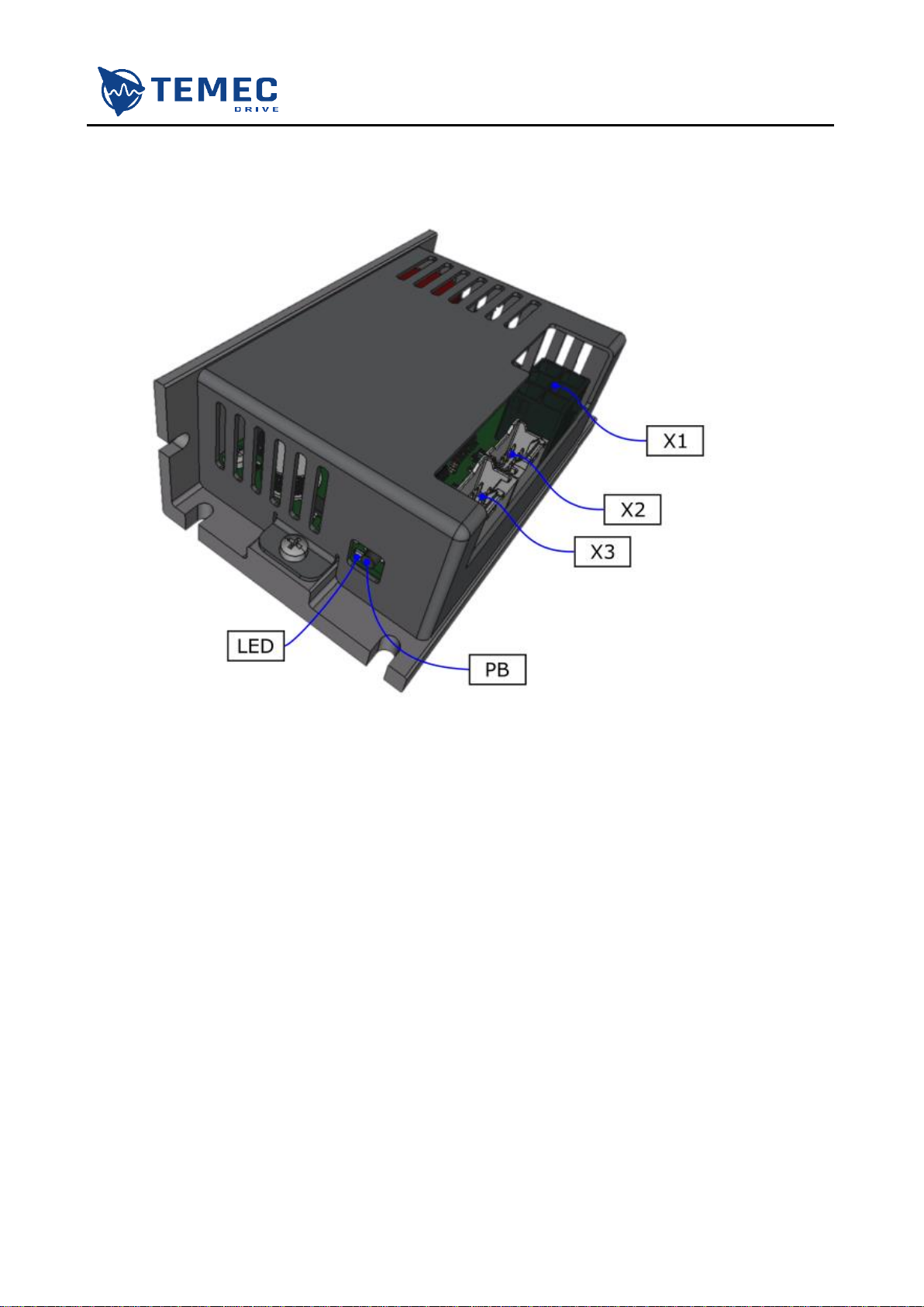
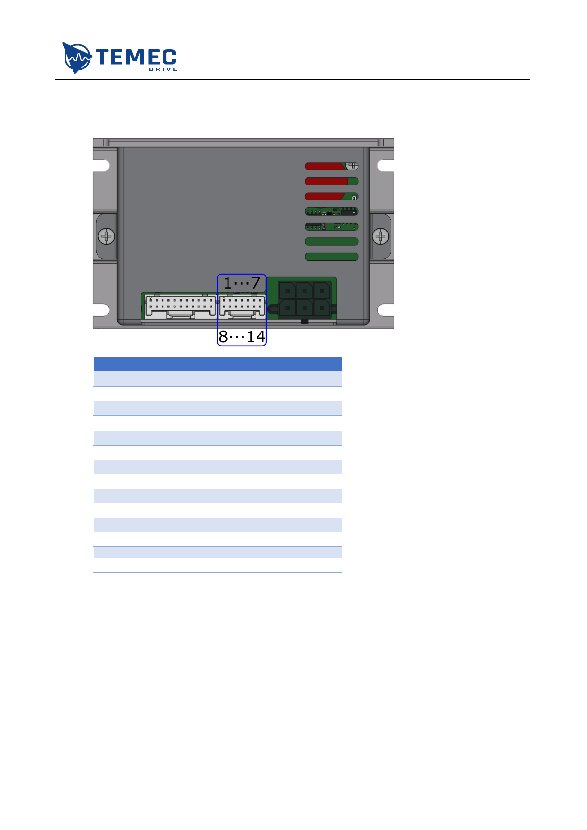
3.4. Electrical connections
During connection of terminals, work with power disabled. The image below shows AZ3 connectors.

AZ3s USER MANUAL
ST.TEC.054
15 / 60
3.4.1. X1 –POWER
X1 is a Molex 0768290006. The following image show X1 pin-out.
It is recommended to choose power cables in function of the current absorbed by the motor.
The counter-part of this connector is a Molex 0768230322 to be used with the socket contacts Molex
1716920106.
PIN
DESCRIPTION
1
U
+M
brushless motor U phase
DC motor positive pole
2
V
brushless motor V phase
3
W
-M
brushless motor W phase
DC motor negative pole
4
BRK-RES
Power output for braking resistor
5
+VDC
Positive supply and ground
6
-VDC
AZ3s USER MANUAL
ST.TEC.054
16 / 60
3.4.2.X2 CONNECTOR
X2 is a Molex 5016451420. The following image shows X2 pin-out.
PIN
DESCRIPTION
1
Hall signal –W
2
Hall signal –V
3
Hall signal –U
4
Motor thermistor
5
Supply +5V DC
6
Ground
7
Power output for electromechanical brake
8
Incremental encoder –CHA+
9
Incremental encoder –CHA-
10
Incremental encoder –CHB+
11
Incremental encoder –CHB-
12
Incremental encoder –CHZ+
13
Incremental encoder –CHZ-
14
Internally connected to positive supply
The counter-part of this connector is a Molex 5016461400 to be used with the socket contacts Molex
5016471000.

AZ3s USER MANUAL
ST.TEC.054
17 / 60
3.4.3.X3 CONNECTOR
X3 is a Molex 5016452220. The following image shows X2-B pin-out.
PIN
DESCRIPTION
1
CANH
2
CANL
3
CANH
4
CANL
5
Ground
6
Internally connected to positive supply
7
Digital input #2
8
Digital input #4
9
Digital output #1
10
Ground
11
Analog input #1
12
RS485 for Modbus communication –A/+
13
RS485 for Modbus communication –B/-
14
UART for PC software communication –TX
15
UART for PC software communication –RX
16
Ground
17
Digital input #1
18
Digital input #3
19
Digital input #5
20
Digital output #2
21
Ground
22
Analog input #2
The counter-part of this connector is a Molex 5016462200 to be used with the socket contacts Molex
5016471000.
AZ3s USER MANUAL
ST.TEC.054
18 / 60
3.4.4.HOW TO CONNECT
Read carefully the following instruction, non-observance of this specification may damage the
drive!
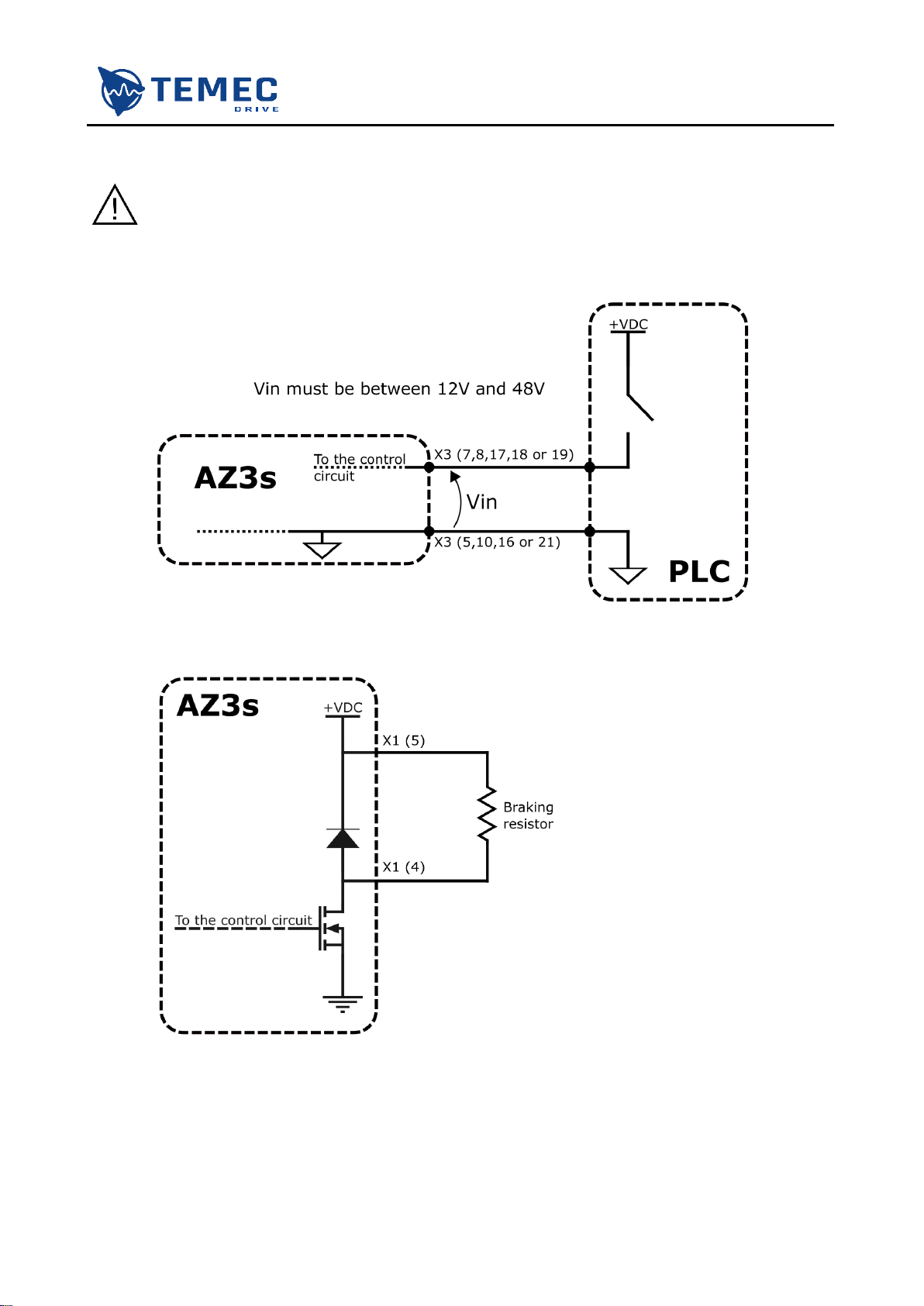
AZ3s has five digital inputs with the following schematic. The input digital inputs voltage must
be between 12 V and 48 V. In the images below a connection examples is shown.
Through power output 4 of X1, the drive can manage a braking resistor without
relay/contactor. The braking resistor must not be lower than 3 Ω.
AZ3s USER MANUAL
ST.TEC.054
19 / 60
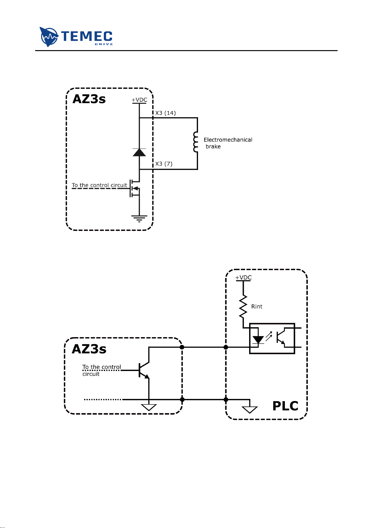
The drive can manage an electromechanical brake without relay/contactor. The current of
the electromechanical brake must not exceed 1 A.
AZ3s has two digital outputs with the following schematic. Do not exceed an input current of
100 mA. Non-observance of this specification may damage the drive. In the images below a
possible connection example.
AZ3s USER MANUAL
ST.TEC.054
20 / 60
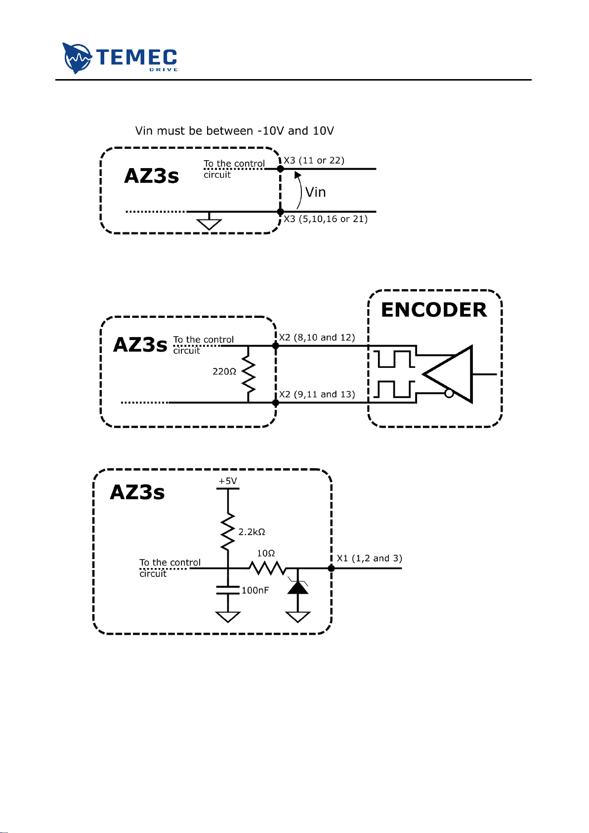
AZ3s has two analog inputs, whose input voltage must be between -10 V and +10 V.
The input stage schematic of channels of incremental encoder is showed in the image below
(the encoder output differential voltage must be between -7 V and 12 V).
The input stage schematic of channels of Hall encoder is showed in the image below.
Refer to chapter 4.2.2 for Hall sequence.
This manual suits for next models
1
Table of contents
Other TeMec Drive DC Drive manuals

Popular DC Drive manuals by other brands


ABB
ABB ACS880-04F-504A-3 Hardware manual

Wittenstein
Wittenstein cyber dynamic system operating manual

Honeywell
Honeywell SmartVFD COMPACT user manual

GFA
GFA ELEKTROMAT ST 9.24-25.00 installation instructions

Festo
Festo EGC-50-TB Instructions & Operating

Danfoss
Danfoss VLT AutomationDrive FC 300 Series Programming guide