TMPOil Furnaces – Furnace Manual
670-000-004/1010 11
4Venting
General venting requirements
Failure to follow all instructions can result in flue gas
spillage and carbon monoxide emissions, causing
severe personal injury or death.
Inspect existing chimney before installing furnace.
Clean chimney thoroughly. Replace or repair
chimney if visual inspection indicates chimney may
be unsuitable for use. Insufficient draft can cause
flue gas leakage and carbon monoxide emissions.
Failure to clean or replace perforated pipe or tile
lining and/or patch mortar and joints can cause
severe personal injury or death.
Proper draft for these oil furnaces may be achieved using either
a conventional chimney (natural draft) or a power vent (sidewall)
system that has been properly designed for use with oil-fired
equipment. Power vent manufacturer’s instructions must be
followed.
Use vent material approved by local codes for oil-fired burners.
In their absence, refer to:
NFPA 31, Installation of Oil-Burning Equipment.
NFPA211, Standard for Chimneys, Fireplaces, Vents and
Solid Fuel Burning Appliances.
In Canada, refer to CSA B139, Installation Code for Oil-
Burning Equipment.
NFPA-211 requires chimney to be lined before connected to
furnace.
To prevent downdrafts, extend chimney at least 3 feet above
highest point where it passes through roof and 2 feet higher than
any portion of building within 10 feet. Increase chimney cross-
sectional area and height at least 4% per 1,000 feet above sea
level.
Provide minimum clearances from vent (flue) pipe to
combustible material:
Single-wall vent – 18 inches minimum
Type“L”double-wallvent–6inchesminimum
Oversized chimneys, outside masonry chimneys
and/or derated inputs can result in condensation in
chimney.
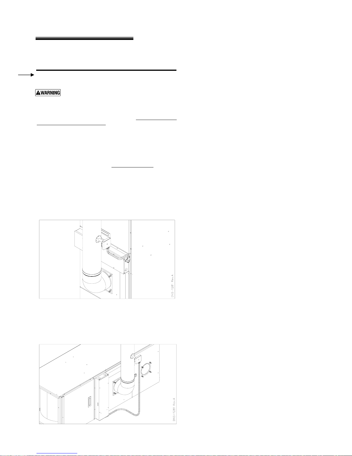
Connect venting
Long horizontal vent runs, excessive number of tees
and elbows, or other obstructions restricting
combustion gas flow can result in the possibility of
condensation, flue gas leakage and carbon
monoxide emissions, which can lead to severe
personal injury or death.
The horizontal vent must slope upwards, away from the furnace,
a minimum of ¼inch per foot.
Connection must be made above bottom of chimney to avoid
blockage. Vent pipe must not enter chimney far enough to cause
obstruction. Use thimble or slip joint where vent pipe enters
chimney to allow removal for cleaning.
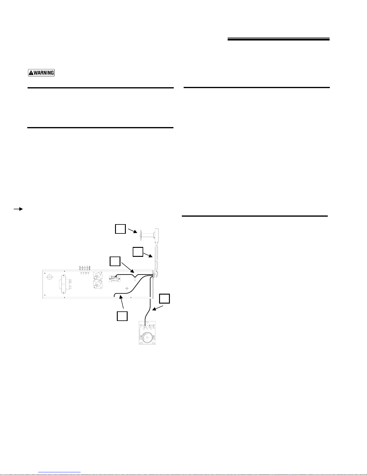
When burner and furnace are properly installed, draft overfire
will be approximately –0.01” to –0.02” w.c. Install barometric
Connect venting (continued)
control in vent, per control manufacturer’s instructions, when
excess draft needs to be relieved or to comply with applicable
codes and regulations. Use draft gauge to adjust proper
opening.
An induced draft fan for the chimney may be necessary if:
Excessive resistance to flow of combustion gases can be
expected.
Cross-sectional area of chimney is smaller than minimum
recommended.
Chimney height is less than recommended.
When using induced draft fan seal all vent joints and
interlock burner with fan operation.
Vent dampers
Do not install a thermal-type vent damper on this
furnace. Failure to comply could result in severe
personal injury, death or substantial property
damage.
If a vent damper is required, use only a motorized
one, installed and wired in the furnace according to
the vent damper manufacturer’s instructions.
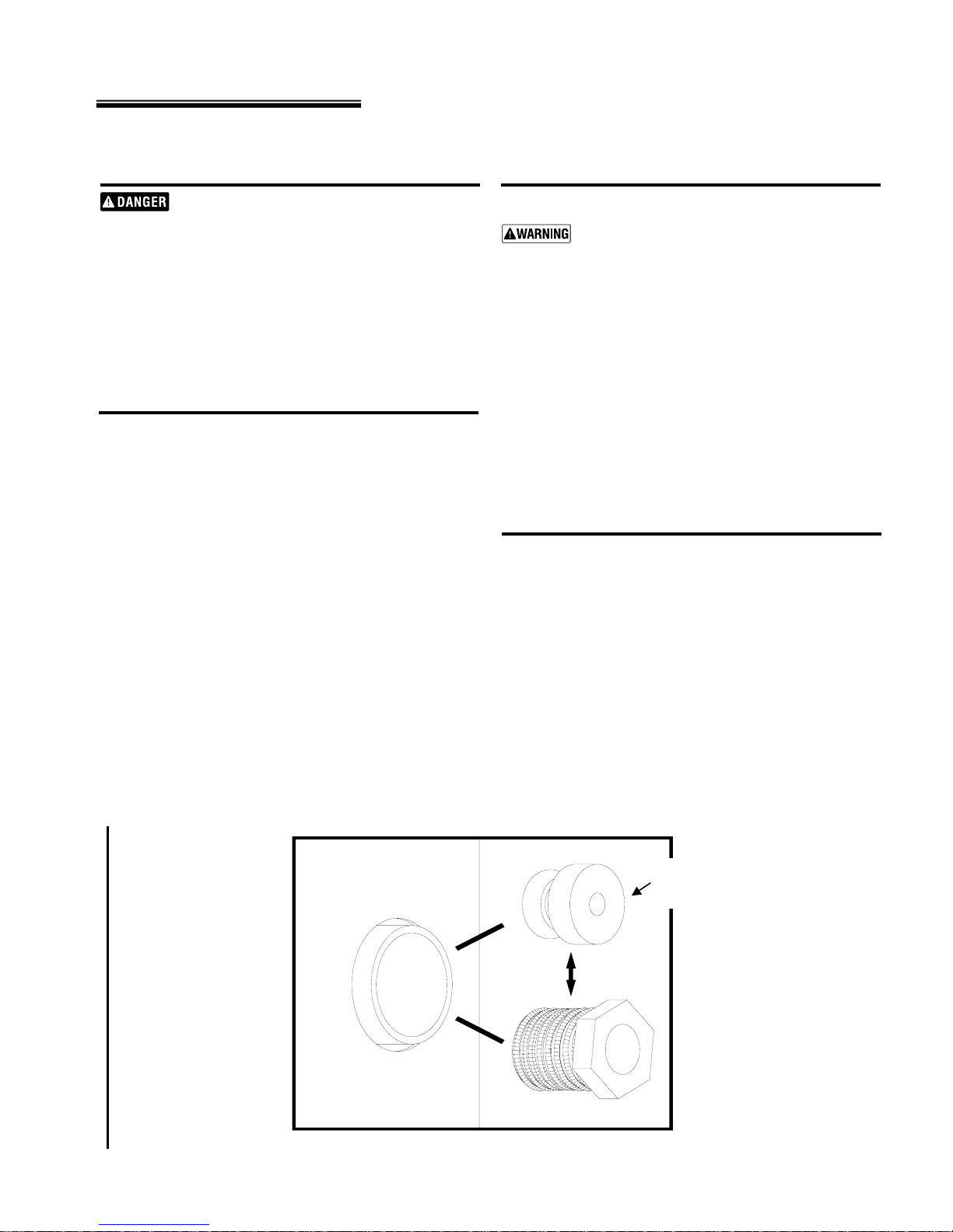
Barometric draft control
Install a barometric control in the vent, per the manufacturer’s
instructions, when excess draft needs to be relieved or to comply
with applicable codes and regulations. Use draft gauge to adjust
proper opening.
Install a barometric draft control in the vent pipe at least one foot
from the furnace vent connection, preferably in the highest part
of the vent pipe before the vent enters the chimney. If headroom
does not provide enough clearance to locate the control at least
one foot from the vent connection, install an elbow at the furnace
and mount the control in an horizontal pipe at least one foot from
the elbow. Install an elbow after the control to turn vertically.
The barometric draft control must be located in the same room
as the furnace to operate correctly.
Ensure that the barometric draft control is accessible. Adjust the
damper to obtain the correct overfire draft, as described in this
manual and the burner manual.