TEMPERED Airwall-250 Series User manual

PLATFORM GUIDE AIRWALL™-250 SERIESInstallation Instructions
Airwall™-250 Series EN DOC-0059 PLATFORM GUIDE
Revision Date: March 2, 2020
TROUBLESHOOTING
If an Airwall is online, you can use the Conductor user interface to download a packet capture le, a
diagnostic report, or a support bundle.
Troubleshoot an Airwall using packet capture:
Packet capture is one of several diagnostic tools that you can use to facilitate troubleshooting an
Airwall.
1. Select Airwalls and choose one from the list and click Diagnostics.
2. Begin packet capture by clicking Start Packet Capture and then stop packet capture by clicking
Stop Packet Capture.
Once the packet capture .pcap le has been created, you get a download link to the le. The .pcap
le is a standard format le that can be viewed using any packet-capture and protocol-analysis tool,
such as Wireshark.
Troubleshoot an Airwall by creating a diagnostic report:
Creating a diagnostic report is one of several diagnostic tools that you can use to get a general over-
view of the health of an Airwall.
1. Select Airwalls and choose one from the list and click Diagnostics. If the Airwall is ofine, you
can put it into diagnostic mode and download a support bundle.
2. Create your report by clicking Request a diagnostic report.
Once the report .txt le has been created, you get a download link to it. The diagnostic report is a text
le that you can examine to see a high-level look at the overall health of the Airwall.
To create a support bundle:
1. Log in to the Conductor with a system administrator or network administrator account.
2. Select Airwalls and choose one from the list and click Diagnostics. If the Airwall is ofine, you
can put it into diagnostic mode and download a support bundle.
3. Create an Airwall support bundle by clicking Request a support bundle. Once the support bundle
.pkg le has been created, you get a download link to the le. A support bundle .pkg le is an encrypt-
ed archive that facilitates technical support by Tempered only.
To provision an Airwall Gateway in diagnostic mode:
1. Congure a computer to use DHCP to obtain an IP address and netmask; then connect the com-
puter to port 2 of the Airwall.
2. Apply power to the Airwall.
3. Place the Airwall into diagnostic mode by pressing and holding the multi-purpose button for three
seconds. The status LED will display a fast blink pattern, as described in the blink patterns section of
this document. Caution: Do not continue pressing the multi-purpose button as this will factory-reset
the Airwall.
4. In your web browser, navigate to http://192.168.56.3. The diagnostic mode interface will load.
5. Click Conguration, and select Conductor URL.
6. Enter the Conductor URL in the Host eld. Click Submit.
7. Reboot the Airwall by selecting the Actions drop-down and clicking Reboot or by turning the
power off and back on again.
To provision an Airwall using DHCP and a DNS SRV record:
For maximum scalability and exibility, the DNS SRV record is the preferred connection type. The
Airwall will use the DHCP-provided search domain to create a DNS SRV query for the Conductor.
Note: Before you begin, ensure there is a DHCP server on your shared network and that a DNS
resolver or DNS server for the local domain is accessible from the shared network.
1. On the DNS server, add a SRV record pointing to the Conductor. SRV records have the following
format:
_service._proto.name TTL class SRV priority weight port target
If your shared network domain is example.com and the Conductor has hostname conductor-01, then
the SRV record should have the following values:
_ifmap._tcp.example.com. 3600 IN SRV 10 0 8096 conductor-01.example.com
The TTL, priority and weight should be determined by your DNS environment and are provided above
as an example. Port 8096 is the default, but you can change it in the Conductor and set it to an
alternate port.
2. Apply power to the Airwall
3. Connect port 1 on the Airwall to your shared network. An IP address, netmask, and a default
gateway are assigned to the Airwall from the DHCP server. The Airwall then does a DNS lookup and
congures itself using the Conductor address.
The Conductor is the central conguration and management point for all Airwall Edge Services.
For provisioning, an Airwall must be able to locate the Conductor on your shared network, either by
manually conguring the IP or URL in diagnostic mode, or by using a DNS SRV record that allows the
AIrwall Gateway to look up the address of the Conductor.
Provisioning the Airwall-250
Deployment Overview
An Airwall appears online in the Conductor user interface once provisioning is complete. An autho-
rized user can then log in to the Conductor, license and manage the Airwall, and then add it to an
overlay network, congure protected devices attached to the Airwall, and enable communication
between other Airwall Edge Services and protected devices. You use port 1 to connect the Airwall to
your shared network and ports 2-8 to connect your local devices.
Note: You can also recongure port assignments from the diagnostic web interface.
• The equipment must be installed in an enclosure that provides a degree of protection not less than
IP 54 in accordance with EN 60079-15 and accessible only by the use of a tool.
• Subject devices are for use in an area of not more than pollution degree 2 in accordance with EN
60664-1.
• Transient protection shall be provided that is set at a level not exceeding 140% of the peak rated
voltage value at the supply terminals to the equipment.
• This equipment is an open-type device that is to be installed in an enclosure only accessible with
the use of a tool, suitable for the environment.
• This equipment is suitable for use in non-hazardous locations only.
Special Conditions of Use
Airwall-250 Series
Ethernet Ports 4 x 10/100/1000 Mbps on RJ-45 ports, auto MDI/MDIX
4 x Combo 10/100/1000 Mbps on RJ-45 ports, auto MDI/MDIX
or 1 Gbps on SFP socket
Console Port 1x Micro USB
Power Input Failover Automatic failover between all inputs
DC Power Input Dual 12-48 VDC on terminal block
Storage Temp range -40° to 85° C (-40° to 185° F)
Operating Temp range -40° to 85° C (-40° to 185° F)
-30° to 70° C (-22° to 158° F) 3GPP Class A (cellular models
only)
Operating humidity 5% to 95%
Dimensions 188mm H x 188mm D x 130mm W (7.4" H x 7.4" D x 5.12" W)
Mounting DIN-rail, wall-mount, or rubber feet
Weight 3.0 kg (6.61 lbs.)
Power-over-Ethernet (PoE)
Operating Mode Auto mode
PoE Power Output Ports 1-8: IEEE 802.3at/af
Max 30W/port
Pin 1/2,7/8(-), Pin 3/6,4/5(+)
Protection Features Overload, surge, and short-circuit protection
Cellular module (Sierra Wireless HL7588) – Supported Bands
4g Cellular Modes LTE: 1900(B2)/ 1700(B4)/ 850(B5)/ 700(B13)/ 700(B17) MHz
LTE Category 4
Downlink: 150 Mbps
Uplink: 50 Mbps
3.5g Cellular Modes UMTS/HSDPA/HSUPA/HSPA+/DC-HSPA+: 1900(B2)/850(B5)
MHz
Data (HSPA+) rates:
Downlink: Up to 42 Mbps (HSDPA category 24) Uplink: Up to
5.76 Mbps (HSUPA category 6)
Cellular antenna connectors 2x SMA female connectors (250g)
4x SMA female connectors (250gd)
SIM card slot 1x externally accessible 3FF micro SIM card slot (250g)
2x externally accessible 3FF micro SIM card slots (250gd)
Serial Interface (Port 1)
Protocols RS-232, RS-422, RS-485 (full and half duplex)
Connector DE-9M
Isolation 2.5 kV minimum
Serial Interface (Port 2)
Protocols RS-422, RS-485 (full and half duplex)
Connector Terminal block
Isolation 2.5 kV minimum
Regulatory Approvals
CE (Airwall-250e only) EN 62368-1:2014, EN55032:2012, EN 55024:2010
cETLus UL 62368-1:2004 (2nd ed.), CSA C22.2 No 62368-1-14 (Ed. 2)
IEC 62368-1:2014 (2nd edition)
IC ICES-3:2016 (Issue 6)
FCC FCC Part 15B Class A”.
FCC Part 22H, Part 24E, Part 27 (for 250g/250gd only)
SPECIFICATIONS
PLATFORM GUIDE AIRWALL™-250 SERIESInformation Security Appliance
EN DOC-0059 PLATFORM GUIDE
Revision Date: March 2, 2020
Airwall™-250 Series
Airwall™-250 Series
Airwall™-250 Series
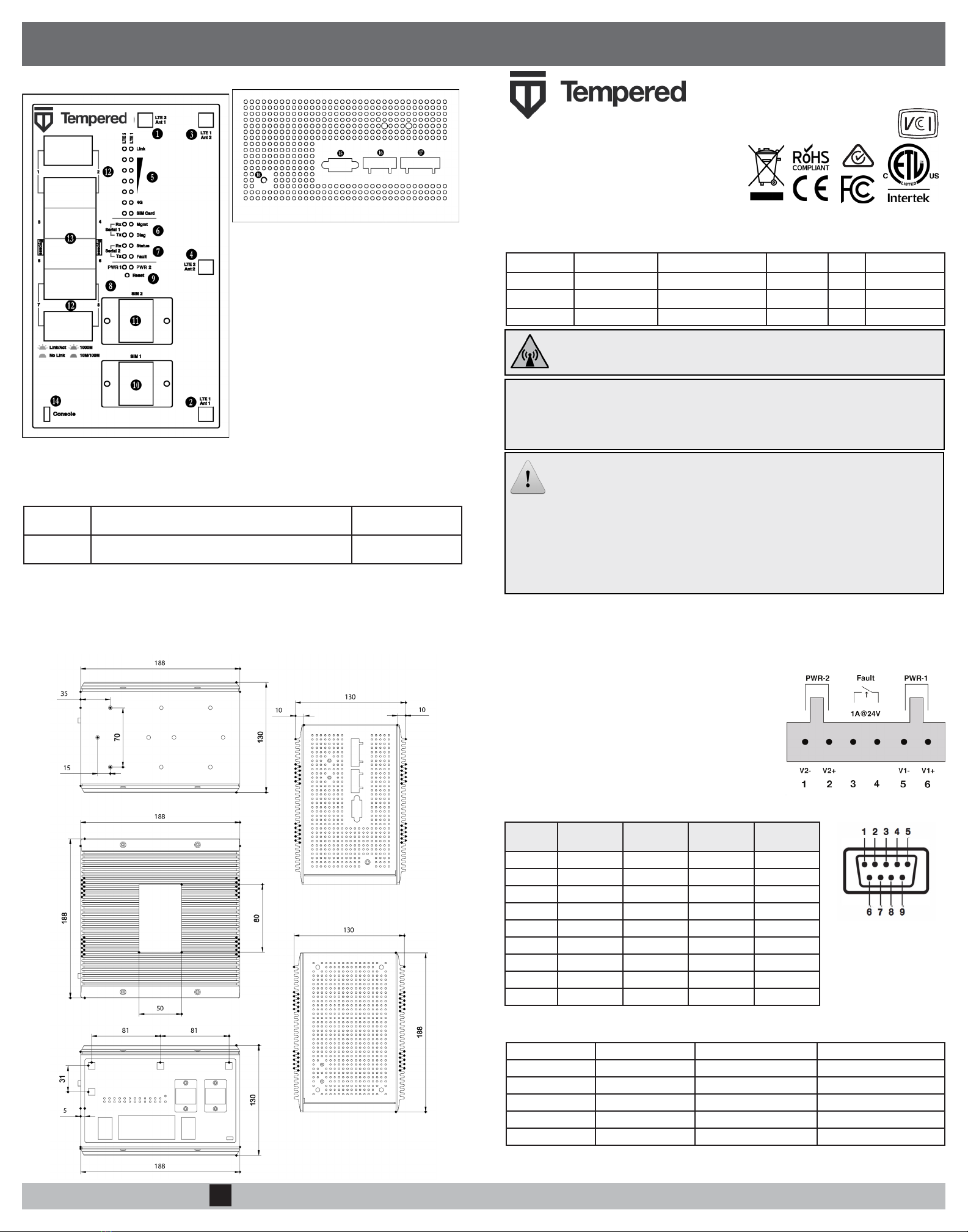
WIRING
Power Inputs
This device supports dual redundant power supplies, power
supply 1 (PWR 1) and power supply 2 (PWR 2). The connec-
tors for PWR 1 and PWR 2 are located on the terminal block.
Step 1: Insert the negative DC into the V- terminal and the
positive DC into the V+ terminal.
Step 2: To keep the DC wires from pulling loose, use a small
at-blade screwdriver to tighten the wire-damp screws in the
front of the terminal block connector.
Serial Connector
Pin # RS-232 RS-422 RS-485
(4-wire)
RS-485
(2-wire)
1DCD Tx- Tx- DATA-
2RxD Tx+ Tx+ DATA+
3TxD Rx+ Rx+ N/C
4DTR Rx- Rx- N/C
5GND GND GND GND
6DSR N/C N/C N/C
7RTS N/C N/C N/C
8 CTS N/C N/C N/C
9 RI N/C N/C N/C
Status LED Codes
Normal Operation On Steady No Conductor Connection O O O O = = O O = =
Conductor Blink O O = = System Error O O O O = = O O O = =
Missing Identity O O O = = O = = Secure Network Error O O O O = = =
Factory Reset O O = = O = = No Shared Network O O O O = = O = =
Diagnostic Mode O = O = (fast blink) Downloading Firmware O O O = = O O = =
Updating Firmware O O O = = =
OBlink =Pause
DIMENSIONS
TOP & FRONT PANEL LAYOUTS
MULTI-PURPOSE BUTTON
NOTE: Some Tempered documents may refer to this as a “Reset” button.
The multi-purpose button provides two different functions, depending on how long it is pressed and
held.
Short Tap Press for 3 seconds and release. The Status LED will now
blink steadily.
Places the Airwall in
diagnostic mode.
Long Tap Press for at least 8 seconds and release. The Status LED
will now blink in a 2 ash, 1 ash pattern,
Resets the Airwall to
factory defaults.
NOTE: To exit diagnostic mode, select Reboot in the diagnostic interface or turn the power of the
Airwall off and back on again.
1. LTE 2, primary antenna connector (250g/250gd)
2. LTE 1, primary antenna connector (250g/250gd)
3. LTE 1, second antenna connector (250g/250gd)
4. LTE 2, second antenna connector (250g/250gd)
5. LED: Signal indicators, LTE modems 1 & 2
6. LED: Serial port 1 activity indicator
7. LED: Serial port 2 activity indicator
8. LED: Power input 1 & 2 indicators
9. Multi-purpose button
10. LTE modem 1 microSIM card slot (250g/250gd)
11. LTE modem 2 microSIM card slot (250g/250gd)
12. Ethernet, Combo RJ-45/SFP ports
13. Ethernet ports
14. Micro-USB console port
15. Serial interface, port 1
16. Serial interface, port 2
17. Power input connector
18. Ground (earthed)
Part Number Model 10/100/1000 Ethernet 4g Cellular Serial 802.3at/af PoE
PLF-0062-02 Airwall-250e 8 No Yes Yes
PLF-0066-02 Airwall-250g 8 Yes Yes Yes
PLF-0111-02 Airwall-250gd 8 Yes Yes Yes
The Airwall™-250 Series is a small form factor indus-
trial grade security appliance that facilitates private
overlay networks between customer-provided equip-
ment and devices. This document contains important
operating information, specications, and installation
instructions.
MODELS
Safety and Warnings
Elevated Operating Ambient: If installed in a closed environment, make sure the operating ambient
temperature is compatible with the maximum ambient temperature specied by the manufacturer.
Reduced Air Flow: Make sure the amount of air ow required for safe operation of the equipment is not compro-
mised during installation.
Mechanical Loading: Make sure the mounting of the equipment is not in a hazardous condition due to uneven
mechanical loading.
Circuit Overloading: Consideration should be given to the connection of the equipment to the supply circuit and
the effect that overloading of the circuits might have on over-current protection and supply wiring. Appropriate
consideration of equipment nameplate ratings should be used when addressing this concern.
e-mail: [email protected]
Phone: +1 206.452.5500 ext. 2
www.tempered.io
19410 Hwy 99, Suite A #119
Lynnwood, WA 98036
FCC Radiation Exposure: This equipment complies with FCC radiation exposure limits set forth for
an uncontrolled environment. This equipment should be installed and operated with minimum distance
of 20cm between the radiator & your body and must not be co-located or operating in conjunction with
any other antenna or transmitter.
Note: This equipment has been tested and found to comply with the limits for a Class A digital device, pursuant to
part 15 of the FCC Rules. These limits are designed to provide reasonable protection against harmful interference
when the equipment is operated in a commercial environment. This equipment generates, uses, and can radiate
radio frequency energy and, if not installed and used in accordance with the instruction manual, may cause
harmful interference to radio communications. Operation of this equipment in a residential area is likely to cause
harmful interference in which case the user will be required to correct the interference at his own expense.
Airwall 250g(d) contains transmitter module: FCC ID: N7NHL7588 / IC ID: 2417C-HL7588
Device Contains Approved Radio: NL-SW-LTE-S7588 CAN ICES-3 (A)/NMB-3(A)
This manual suits for next models
6
Other TEMPERED Firewall manuals

Popular Firewall manuals by other brands


Aaeon
Aaeon FWS-2260 user manual

NETGEAR
NETGEAR FVS318 - ProSafe VPN Firewall Router installation guide

Fortinet
Fortinet FortiGate 50B-LENC quick start guide

SonicWALL
SonicWALL NSa 5700 quick start guide

McAfee
McAfee NS Series Product guide

Ruijie
Ruijie RG-WALL1600-M6600 Hardware installation and reference guide