TEMPERED 500 Series Assembly Instructions

PLATFORM GUIDE
Revision Date: Apr 14, 2021DOC-0005
EN
500 Series Hardware
PLATFORM GUIDE 500 SERIES HARDWAREConductor-500 and Airwall-500
Front Panel Layout
500 Series Hardware
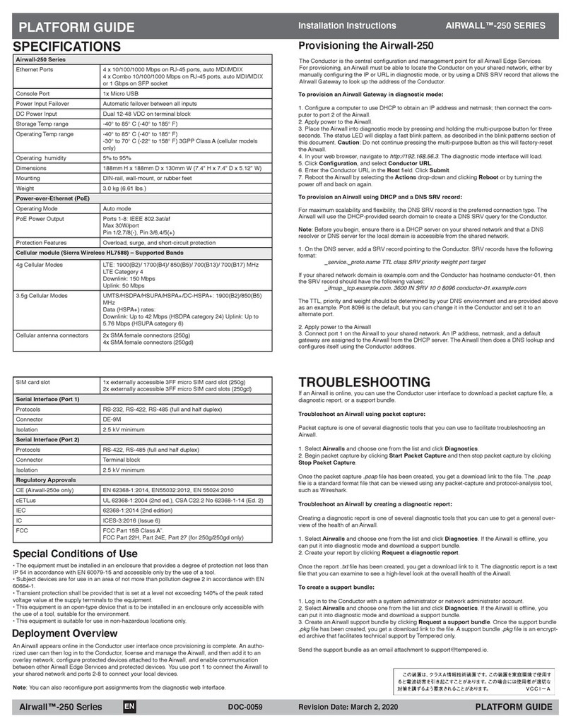
Ethernet Ports 8 x GbE on RJ-45 ports 1000/100/10M
2 x SFP GbE 1000/100M
Ethernet Expansion Bays 1
Power Supply (dual) 100-240V, 47-63Hz
Power Consumption 270W, max
Controls 1 Reboot button (actuated with pin)
1 Reset button (actuated with pin)
4 Push-buttons for LCD display unit
1 Power supply alert mute (back of unit)
Displays 1 Power LED
1 Activity LED
1 Status LED
1 Alert LED
1 2-line x 20-character LCD conguration and management
front panel
Storage Temp range -20° to 70° C (-4° to 158° F)
Operating Temp range Primary power: 0°C to +45°C (+32°F to +113°F)
Secondary power: 0°C to +40°C (+32°F to 104°F)
Operating humidity 5% to 90%, non-condensing
Dimensions 450mm W x 430mm D x 44mm H (17.7” W x 16.93” D x
1.74” H)
Mounting 1U rack mount
Weight 8.5 kg (18.74 lb)
Specications
The Conductor-500 and Airwall-500 are 1U rack-mount security appliances that facilitate private overlay
networks between customer-provided equipment and devices.
Both the Conductor and Airwall Gateway have a unique public/private 2048-bit key pair and a
Tempered® signed certicate that establishes a chain of trust to a Tempered® certicate authority. The
Conductor and Airwall use these certicates to authenticate to each other and establish secure commu-
nications over trusted and untrusted networks.
This guide contains instructions for conguring both the Conductor-500 and the Airwall-500.
e-mail: [email protected]
Phone: +1 206.452.5500 ext. 2
www.tempered.io
19410 HWY 99 STE A #119
Lynnwood, WA 98036
Regulatory Approvals
CE EN 55032: 2015 / AC: 2016 CISPR 32: 2015 (Ed
2.0) / C1: 2016
EN 61000-3-2: 2014, EN 61000-3-3: 2013
IEC IEC 60950-1:2005 (2nd edition), Am 1:2009, Am
2:2013
FCC Part 15B Class A
AS/NZS CISPR 32: 2015 CISPR 32: 2015 (Ed 2.0) / C1:
2016
VCCI VCCI-CISPR 32: 2016
1 Buttons for LCD display navigation 5Power LED 98x RJ45 Ethernet ports
2LCD display panel 6Activity indicator LED 10 2x SFP ports
3 Diagnostic/Reset button 7Status LED 11 1x Expansion bay
4(non-functional) 8Alert LED (functional for the Airwall-500 only)
12
3
4
5 6
789 10
11
Ethernet Expansion Module: 2-port SFP+ (Airwall-500 only)
Ethernet Ports 2 x 10GbE SFP+
Type Fiber
Ethernet Expansion Module: 8-port RJ45 (Airwall-500 only)
Ethernet Ports 2 8 x 1GbE RJ45
Type Copper
Ethernet Expansion Module: 8-port RJ45/SFP
(Airwall-500 only)
Ethernet Ports 4 x 1GbE RJ45
4 x 1GbE SFP
Type Mixed
Back Panel Layout
1Future expansion slots 3Power switch 5Silence Alarm button
2Case exhaust fans 4Case cover removal tab 6Dual power supply (both required)

PLATFORM GUIDE 500 SERIES HARDWAREConductor-500 and Airwall-500
500 Series Hardware EN DOC-0005 PLATFORM GUIDE
Revision Date: Apr 14, 2021
The Conductor has a static IP address congured on its underlay port. To continue initial
setup, connect a workstation to port 1 on the Conductor. Only use Port 1 or Port 2.
Do not use any other ports.
Step 1: Log in and secure the system administrator account:
1. The Conductor is congured with IP address: 192.168.56.2
2. Congure your computer with an IP address in the 192.168.56.0/24 subnet,
e.g. 192.168.56.100
3. In a web browser, connect to https://192.168.56.2
4. Enter the default system administrator username admin
5. Enter the default system administrator password admin123
6. Change the default system administrator credentials when prompted.
Step 2: Connect the Conductor to your underlay
Provision the Conductor-500
You use Diagnostic mode to initially provision an Airwall and congure the settings that are most appropriately controlled locally or that cannot depend on connec-
tivity to Conductor.
To place the Airwall in diagnostic mode:
Press and hold the Diagnostic/Reset button on the front panel for 3 seconds. The Status LED will ash in fast, steady pattern, indicating the unit is in diagnostic
mode.
CAUTION: Do not continue pressing the reboot button for more than 5 seconds as this will factory-reset the Airwall.
Once in diagnostic mode, all device network ports are temporarily bridged together and assigned a temporary IP address of 192.168.56.3, and a DHCP server
is temporarily active on the ports. In this conguration, you can connect a workstation directly and use it to access the diagnostic mode UI via a basic web user
interface active on the device network ports. This UI is used for basic settings and information displays.
The Conductor is the central conguration and management point for Airwall Gateways and they must be able to locate the Conductor on the underlay.
To congure the Airwall:
1. Apply power to the Airwall.
2. Place the Airwall into diagnostic as described above.
3. Congure a workstation to use DHCP to obtain an IP address and netmask, then connect the workstation to any of the device network ports of the Airwall.
4. Open a web browser on the workstation and navigate to http://192.168.56.3 and the diagnostic mode user interface will load.
5. Click on the Conguration drop down, click on Conductor URL and enter the Airwall Conductor URL in Host eld and 8096 in the Port eld.
• If the hostname of the Airwall Conductor is conductor-01.example.com, the URL should be entered as https://conductor-01.example.com
• If the IP address of the Airwall Conductor is 192.168.56.2, the URL should be entered as https://192.168.56.2
NOTE: You must use HTTPS, and connection on port 8096.
6. Click Submit.
7. Reboot the Airwall to return it to normal operating mode. You can reboot it by selecting Diagnostic/Reboot in the diagnostic mode user interface, or by turn-
ing the Airwall off and back on again.
Once the Airwall is correctly provisioned, it appears in the Conductor user interface, where you can further congure and manage it.
Provisioning the Airwall-500
Additional Documentation
If you require additional information about conguring or managing your 500-series hardware, see Airwall help at https://webhelp.tempered.
io/webhelp.
Once you have secured the system administrator account, you can connect the Conductor to the underlay using the NIC congured previously. After you connect
the Conductor to the underlay, you can connect to the web-based administrator UI via the hostname or IP address you congured during initial setup.
Step 3: Enter Conductor system conguration information
Once you successfully log in from the Conductor UI and change the default login information, you enter basic conguration information for your Conductor in the
System Conguration dialog.
On either the Network Adapter 1 or Network Adapter 2, select one of the following:
• DHCP to dynamically obtain an IP address from the shared network.
• A DNS hostname for the Conductor. This hostname will be included in the DHCP request to facilitate DNS registration.
• A static IP address that will be valid on the underlay.
Note: When you click Update Settings, you may lose your current connection to the Conductor while the settings are applied. You can log back into the Conduc-
tor once the conguration is complete.
For the latest info,
see Airwall help:
Safety and Warnings
Elevated Operating Ambient: If installed in a closed envi-
ronment, make sure the operating ambient temperature is
compatible with the maximum ambient temperature specied by
the manufacturer.
Reduced Air Flow: Make sure the amount of air ow required for safe oper-
ation of the equipment is not compromised during installation.
Mechanical Loading: Make sure the mounting of the equipment is not in a
hazardous condition due to uneven mechanical loading.
Circuit Overloading: Consideration should be given to the connection of
the equipment to the supply circuit and the effect that overloading of the
circuits might have on over-current protection and supply wiring. Appropri-
ate consideration of equipment nameplate ratings should be used when
addressing this concern.
Explosion Hazard: Do not disconnect equipment unless power has been
removed or the area is known to be non-hazardous.
This manual suits for next models
2
Table of contents
Other TEMPERED Firewall manuals
Popular Firewall manuals by other brands
Ruijie Networks
Ruijie Networks RG-WALL1600-S3600 Hardware installation and reference guide
NETGEAR
NETGEAR FVG318v2 - ProSafe 802.11g Wireless VPN Firewall... installation guide
H3C
H3C SecPath F100-C installation manual

Tosibox
Tosibox Lock 200 quick start guide
H3C
H3C SecPath Series Command reference

Blue Coat
Blue Coat SG810 series installation guide
