Templari KITA AIR R32 User manual
INSTALLATION INSTRUCTION
AIR TO AIR
Refrigerant gas
THE HEAT PUMP

Summary
1 Introducon ........................................................................................................... 6
1.1 General Notes......................................................................................................... 6
1.2 Suggested tools ...................................................................................................... 6
1.3 Seriesdescripon ................................................................................................... 6
2 Read Carefully before use ....................................................................................... 7
2.1 Importantinformaon............................................................................................ 7
2.2 Importantinformaonregardingtherefrigerantused ............................................ 7
2.3 Proper use.............................................................................................................. 8
2.4 Standards and statutory provisions......................................................................... 8
2.5 Instruconsfordisposal ......................................................................................... 8
2.6 Energecsaving...................................................................................................... 8
3 Expecteduseoftheheatpump .............................................................................. 8
3.1 Operangareaesafedevices ................................................................................. 8
3.2 Allowedoperavezone .......................................................................................... 8
3.3 Heat pump structure .............................................................................................. 9
3.4 Operaonmode ..................................................................................................... 9
4 Equipment supplied................................................................................................ 9
4.1 Main unit................................................................................................................ 9
4.2 Name and serial number ........................................................................................ 9
4.3 KITA AIR R32 Templari® external unit components diagram ................................. 11
4.4 KITA AIR Plus R32 Templari® external unit components diagram........................... 12
4.5 KITA AIR R32 and AIR Plus R32 Templari® internal unit components diagram........ 13
5 Transport.............................................................................................................. 14
6 Mounngandinstallaon..................................................................................... 14
6.1 Equipmentcheck .................................................................................................. 14
6.2 External unit measurements................................................................................. 14
6.3 Freespacesfortheassembly ................................................................................ 15
6.4 Choiceofinstallaonplace ................................................................................... 15
6.5 Externalunitmounng ......................................................................................... 16
6.6 Condensatedischargepreparaon........................................................................ 16
6.7 Correct alignment................................................................................................. 17
7 Installaonandassemblyoftheinternalunit ....................................................... 17
7.1 InternalunitsizesKITAAIRR32............................................................................. 17
7.2 Generaliesandchoiceoftheinstallaonplace ................................................... 18
7.3 AssemblyinternalunitandcorrectposioningofB2probe .................................. 18
8 Refrigerantcircuitconnecon............................................................................... 18
8.1 Installaonrequirements ..................................................................................... 18
8.2 Setupforinstallaonandrefrigerantpipelinesinstallaon .................................. 19
8.3 Vacuum procedure ............................................................................................... 19

9 Maintenance and cleaning.................................................................................... 19
9.1 Finned coil cleaning .............................................................................................. 19
9.2 Condensatedischargecleaning............................................................................. 20
9.3 Refrigerant circuit maintenance............................................................................ 20
10 Electricconnecon ............................................................................................... 20
10.1 Generalinformaon ............................................................................................. 20
10.1.1Thecustomer/installerhasto: ............................................................................. 20
10.2 Operaonsoflaying ............................................................................................. 20
10.3 Externalunitconnecon....................................................................................... 20
10.4 Internalunitconnecon ....................................................................................... 20
10.5 Probes and remote controller ............................................................................... 20
10.6 Power supplying ................................................................................................... 20
10.6.1Internalunitauxiliaryheater(oponal) ................................................................ 21
10.7 Powerandsignalcablescharacteriscs................................................................. 21
11 Terminal box wiring .............................................................................................. 22
11.1 Mono-phaseinternalterminalboxwiring............................................................. 22
11.2 3-phaseinternalterminalboxwiring .................................................................... 22
12 Electronics(UPC) .................................................................................................. 24
12.1 Digital outputs...................................................................................................... 24
12.2 Digital inputs ........................................................................................................ 24
12.3 Analogical outputs................................................................................................ 24
12.4 Analogical inputs .................................................................................................. 24
12.5 KITAAIRR32andAIRPLUSR32electricdiagram................................................... 25
12.6 Internalunitwiringconnecon............................................................................. 26
12.6.1 Fan....................................................................................................................... 26
12.6.2 4-way valve and carter resistance wiring .............................................................. 26
12.6.3 wiring probe ........................................................................................................ 26
12.7 KITAAIRR32andAIRPLUSR32internalunitauxiliaryheangelement(oponal)
wiringconnecondiagram ................................................................................... 27
13 Commissioning ..................................................................................................... 28
13.1 Preliminary controls ............................................................................................. 28
13.2 Commissioning ..................................................................................................... 28
14 K-TouchPanel ....................................................................................................... 28
14.1 Warnings .............................................................................................................. 28
14.2 ConnecngtotheKitaheatpump........................................................................ 29
14.3 System overview .................................................................................................. 30
14.4 Explodedview:PLanconnecon(7a)orBMSconnecon(7b) .............................. 32
15 Control unit .......................................................................................................... 34
15.1 Fixingofthepanel ................................................................................................ 34
15.2 Control panel measurement ................................................................................. 34
15.3 Control panel structure......................................................................................... 34
15.4 Control panel display............................................................................................ 34
15.5 Main menu........................................................................................................... 35

15.6 ON-OFF menu....................................................................................................... 35
15.7 SETPOINT menu.................................................................................................... 35
15.8 Clock/metablemenu .......................................................................................... 36
15.9 Input/Outputmenu.............................................................................................. 37
15.10Alarmshistorymenu ............................................................................................ 37
15.11Boardchangemenu.............................................................................................. 37
15.12 Assistance menu................................................................................................... 37
15.13 Menu overview .................................................................................................... 41
16 Alarms.................................................................................................................. 42
16.1 Alarmsresoluon ................................................................................................. 44
16.2 Nocaons......................................................................................................... 44

6
www.templari.com
1 Introducon
KITA - AIR Templari® heat pump, from
its start-up and for all its life cycle. The document is divided
procedures to be performed.
gases covered by the Kyoto Protocol. Do not
vent gases into the atmosphere.
take extreme care that there are no sources of
requirements in paragraph 6.4.
1.1 General Notes
the system.
• The unit is directly supplied by the manufacturer with all
pump KITA - AIR Templari® can prevent damages and any
costs for repairs.
• Keep this manual with the necessary diagrams in an easily
accessible place.
control panel, if necessary contact the installer. If necessary,
please request for original parts.
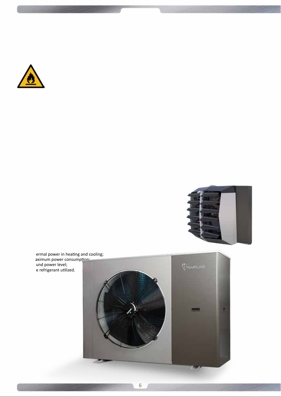
• Voltage and frequency of Power supply of the machine;
• Sound power level;
1.2 Suggested tools
• Set of screwdrivers;
• Scissors;
• Set of wrenches or pipe wrenches;
• Pumber material to seal the threads;
• Testers and current clamp;
1.3 Seriesdescripon
KITA - AIR Templari® heat pump series presents air to air
machines which are composed by an external and internal
KITA - AIR Templari® is full-inverter with high performance and
Another feature is the EVI technology (Enhanced Vapour
a 4-ways valve, pressure transducers, temperature probes,
controlled by the electronics onboard. The user can control the
this control it is possible to change the setpoint and the working
Internal unit
External unit
7
www.templari.com
2 Read Carefully before use
2.1 Importantinformaon
ATTENTION!!
The use and the maintenance of the KITA - AIR Templari®
heat pump, are subjected to the juridical ordinances of the
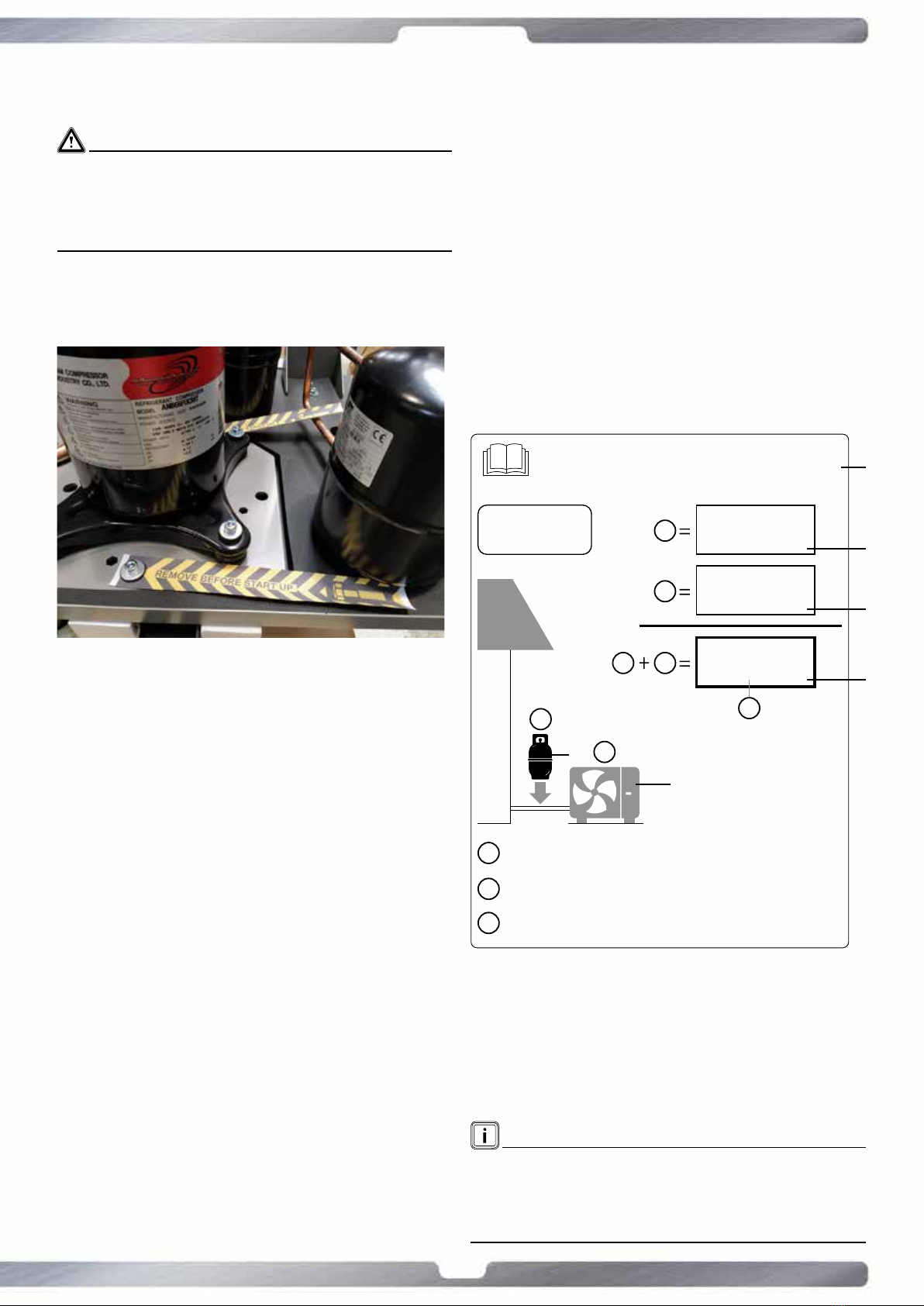
• Transport protecon must be removed before to
commissioning.
countries.
• If the heat pump is installed near the wall, be careful to the
• If the heat pump is installed near a wall, there is a higher
by the heat pump must escape in order to not increase the
building thermal losses.
the monoblock in niches or in interior courtyards, because
the cooled air accumulates on the ground and in the case
pump.
wiring the start of the heat pump is hindered. The unit
presents a phase monitoring that indicates the correct
please see the commissioning procedure explained
forward.
electronics.
the device.
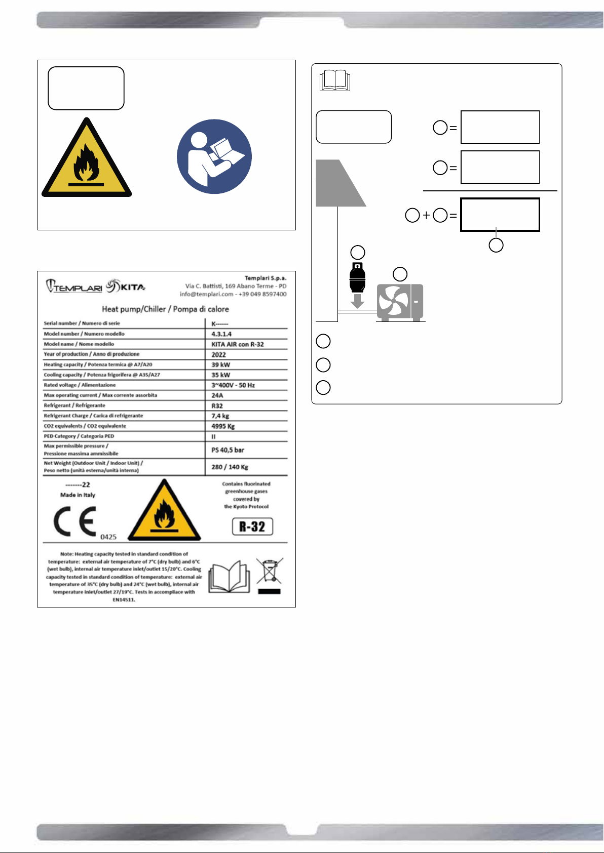
2.2 Importantinformaonregardingthe
refrigerant used
the Kyoto Protocol. Do not vent gases into the atmosphere.
• the factory refrigerant charge of the product,
•
• +the total refrigerant charge
product.
R32
Contiene gas uorurati ad effetto serra inclusi nel protocollo di Kyoto
Contains uorinated greenhouse gases covered by the Kyoto Protocol
Enthält uorierte Treibhausgase, die durch das Kyoto-Protokoll abgedeckt
warden
1
1
2
3
2
Carica di refrigerante di fabbrica del prodotto: vedi targhetta con il nome
dell’unità / Factory refrigerant charge of the product: see unit name plate / Werkseitige
Kältemittelbefüllung des Produktes: siehe Typenschild der Einheit
Quantità di refrigerante aggiuntiva nel campo / Additional refrigerant amount charged in
the eld / Zusätzliche am Montageort befüllte Kältemittelmenge
Carica di refrigerante totale / Total refrigerant charge / Gesamte Kältemittelbefüllung
1
2
2
3
1
Kg
Kg
Kg
A
B
C
D
E
F
A
B
Ctotal refrigerant charge
D
Protocol
Eoutdoor unit
Frefrigerant cylinder and manifold for charging
NOTE!
8
www.templari.com
working environments, which may otherwise lead to deposits on
3 Expecteduseoftheheat
pump
3.1 Operangareaesafedevices
KITA AIR Templari® heat pump has to be used with external air
• Heang
• Cooling
• KITA AIR Templari® heat pump is equipped by a pressure
ATTENTION!
• KITA AIR Templari® heat pump is equipped by a
discharge temperature probe that controls the discharge
temperature.
NOTE!
The device is not suitable for use with an external inverter. If the
periods, do not interrupt the procedure of the oil warming that
starts when the machine is powered once again. This procedure
prevents the compressor breakdown.
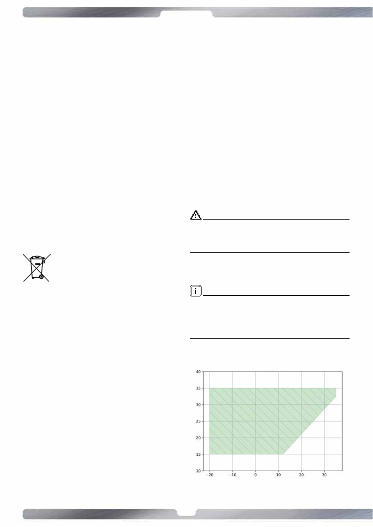
3.2 Allowedoperavezone
Heangmode
Outside air temperaturer ± 2 [°C]
Internal air temperaturer ± 2 [°C]
2.3 Proper use
2.4 Standards and statutory provisions
were observed in the design and manufacture of the heat pump
be carried out in accordance with the applicable VDE, EN and IEC
of mains supply network operators must be observed.
Persons, especially children, who on the basis of their physical,
must not use the device without the supervision
or guidance of a competent person. Ensure that
children do not play with the device.
2.5 Instruconsfordisposal
PRODUCT COMPLIES WITH EU DIRECTIVE 2012/19/EU-
LEGISLATIVEDECREE49/2014pursuanttoArt.26ofLegislave
DecreeNo.49of14March2014“ImplementaonofDirecve
2012/19/EU on waste electrical and electronic equipment
(WEEE)”.
The crossed-out wheelie bin symbol on the equipment or its
packaging indicates that the product must be collected separately
from other waste at the end of its useful life.
The removal of the appliance, as well as the retrieval of coolant,
oil or any other parts, must be carried out in accordance with
system, as well as the retrieval of refrigerant, oil or any other
The units must be processed at a facility specialising in material
reuse, recycling and recovery. Proper disposal of the product will
2.6 Energy saving
safeguarding the environment. A prerequisite for reducing

9
www.templari.com
Cooling mode
Internal air temperaturer ± 2 [°C]
Outside air temperaturer ± 2 [°C]
3.3 Heat pump structure
• TheKITAAIRTemplari® external unit contains the refrigerant
circuit;
• KITA AIR Templari®
•
•
3.4 Operaonmode
Heangmode
4 Compressor
5 Electronic expansion
valve
6 Internal unit
exchanger
Cooling mode
4 Compressor
5 Electronic expansion
valve
6 Internal unit
exchanger
4 Equipment supplied
4.1 Main unit
The KITA AIR Templari®
consists of components which are indicated at page 4.
4.2 Name and serial number
The name of the model and the serial number are indicated on
2
1
3
gure 1
10
www.templari.com
R-32 This equipment contains fluorinated greenhouse gases
covered by the Kyoto Protocol.
Read the instruction manual carefully before making any operation.
Leggere attentamente il manuale di istruzioni prima di effettuare qualsiasi operazione.
Questa apparecchiatura contiene gas fluorurati ad
effetto serra inclusi nel protocollo di Kyoto.
R32
Contiene gas uorurati ad effetto serra inclusi nel protocollo di Kyoto
Contains uorinated greenhouse gases covered by the Kyoto Protocol
Enthält uorierte Treibhausgase, die durch das Kyoto-Protokoll abgedeckt
warden
1
1
2
3
2
Carica di refrigerante di fabbrica del prodotto: vedi targhetta con il nome
dell’unità / Factory refrigerant charge of the product: see unit name plate / Werkseitige
Kältemittelbefüllung des Produktes: siehe Typenschild der Einheit
Quantità di refrigerante aggiuntiva nel campo / Additional refrigerant amount charged in
the eld / Zusätzliche am Montageort befüllte Kältemittelmenge
Carica di refrigerante totale / Total refrigerant charge / Gesamte Kältemittelbefüllung
1
2
2
3
1
Kg
Kg
Kg
11
www.templari.com
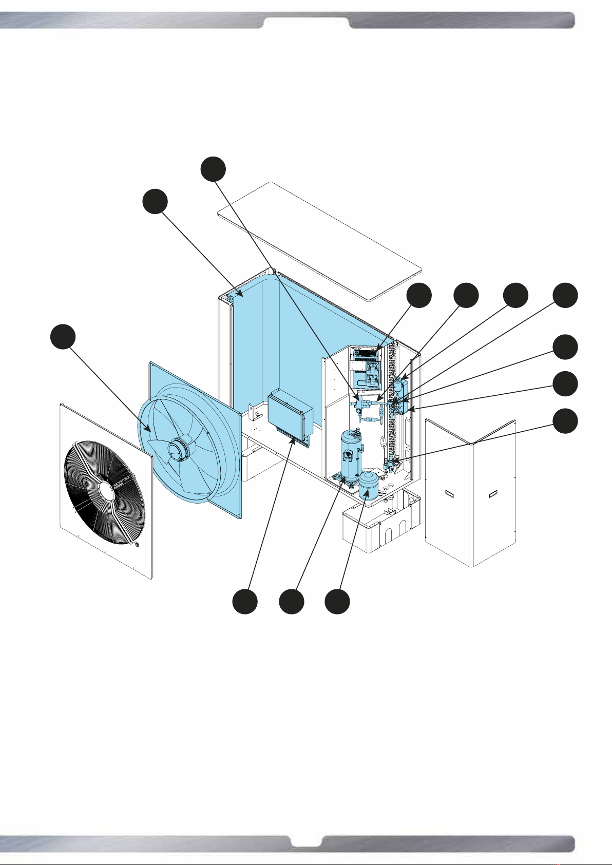
4.3 KITA AIR R32 Templari® external unit components diagram
4
6
9
DATE :
DRAWN BY :
DESCRIPTION:
TEMPLARI SRL - HEAT PUMP TECNOLOGY
Via Pitagora, 20A - 35030 Rubano (PD)
Tel. +39 049 5225929 - www.templari.com
G. Zaccheo
KITA AIR
R32
EXTERNAL UNIT
15/03/2022
This drawing is the property of templari srl, any reproduction and/or distribution without templari srl approval is unlawful.
Il presente disegno è di proprietà di Templari Srl. La riproduzione totale e/o parziale e la divulgazione a terzi, senza nostro esplicito consenso scritto, verrà perseguita a norma di legge.
13
1
5 10 3 11
4
8
9
627
12
12
www.templari.com
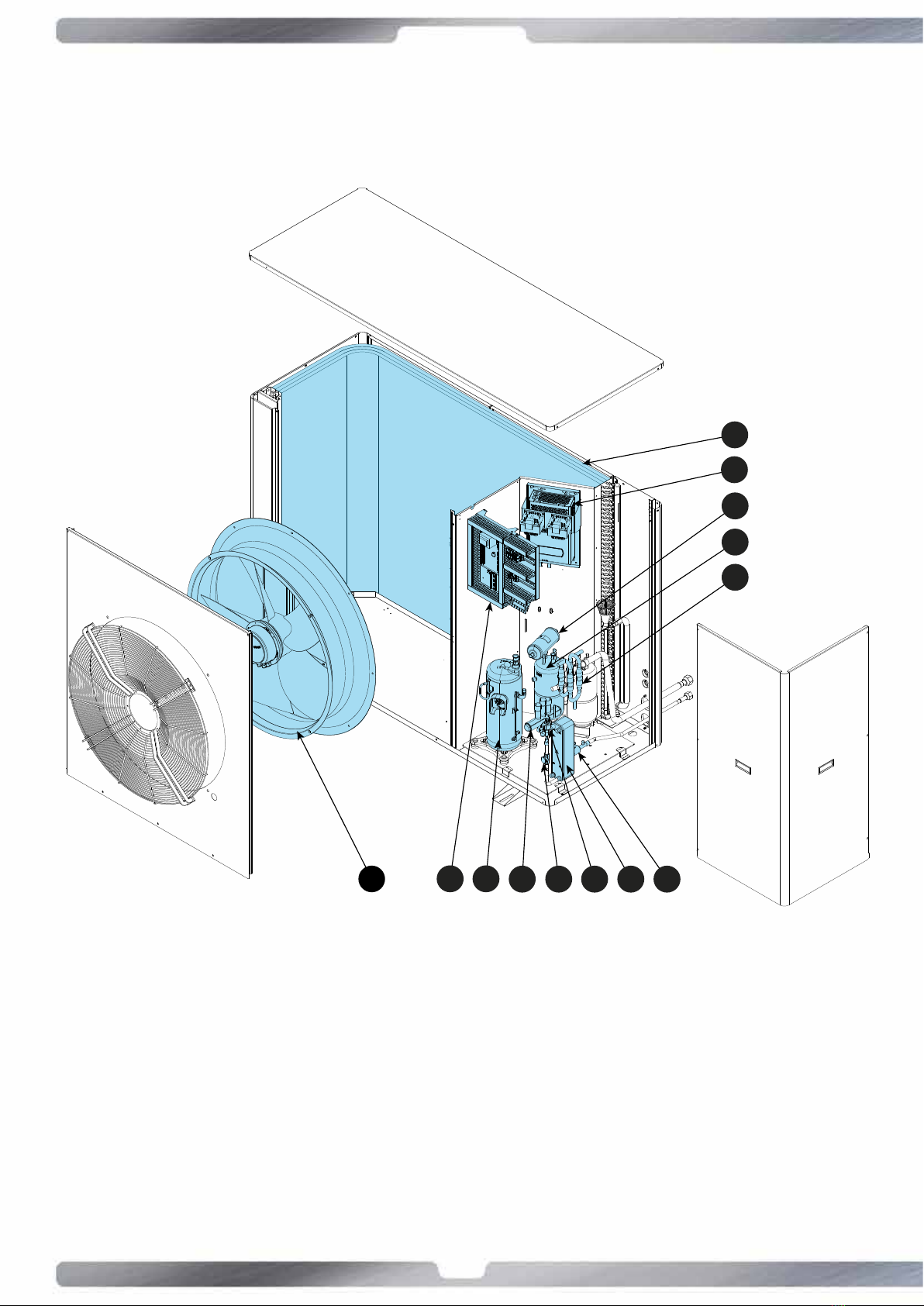
4.4 KITA AIR Plus R32 Templari® external unit components diagram
TEMPLARI SRL - HEAT PUMP TECNOLOGY
Via Pitagora, 20A - 35030 Rubano (PD)
Tel. +39 049 5225929 - www.templari.com
1
3
6
5
10
13 24
78 91112
4
6
9
13
www.templari.com
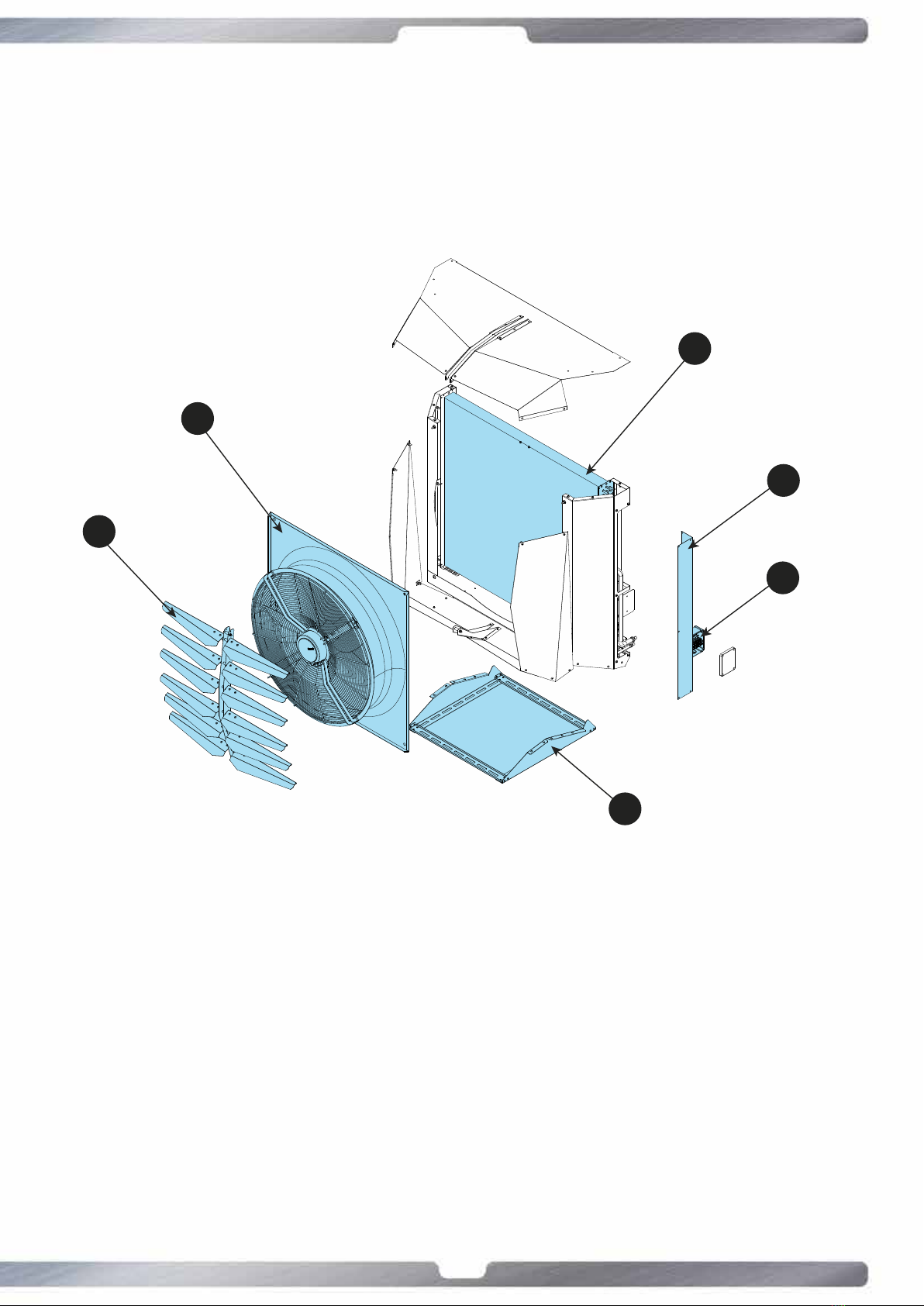
4.5 KITA AIR R32 and AIR Plus R32 Templari® internal unit components diagram
1 Deettore
2 Ventilatore
3 Batteria alettata
4 Quadro elettrico
5 Coperchi laterali
6 Basamento
DATE :
DRAWN BY :
DESCRIPTION:
TEMPLARI SRL - HEAT PUMP TECNOLOGY
Via Pitagora, 20A - 35030 Rubano (PD)
Tel. +39 049 5225929 - www.templari.com
G. Bacca
KITA AIR
INTERNAL UNIT
UNITA' INTERNA
15/09/2021
1
2
3
4
5
6

14
www.templari.com
5 Transport
WARNINGS!
than 45°. Contrary you can have anomalies in the refrigerant
consequence a failure inside.
a pallelt. The heat pump KITA AIR Templari® can be transported
KITA AIR R32 Kg. 280 + 130
KITAAIRPLUSR32Kg.320+140
• Protect the sidewalls of the product coming into contact
example.
• Consider the weight of the product riported in the technical
data.
and the provisions in force.
two persons.
6 Mounngandinstallaon
6.1 Equipmentcheck
• sensor probe
oponal
• wall support for internal unit.
6.2 External unit measurements
KITA R32
WITH LEGS
Agas flow / passaggio refrigerante (gas)
outer diameter / diametro esterno : 22mm
Bliquid flow / passaggio refrigerante (liquido)
outer diameter / diametro esterno : 12mm
Ccondensate drain / scarico condensa
outer diameter / diametro esterno: 40mm
Delectrical wiring / passaggio cavi ele�rici
WITH LEGS
CON GAMBE
WITH BRACKETS
CON STAFFE
DATE :
DRAWN BY :
DESCRIPTION:
TEMPLARI SRL - HEAT PUMP TECNOLOGY
Via Pitagora, 20A - 35030 Rubano (PD)
Tel. +39 049 5225929 - www.templari.com
Giovanni B.
KITA L
SPLIT VERSION
06/03/2020
1513
256 1257
325 1133 325
1791
641
88
289
292
1791
61
136
137
C
A B D
1292
35 1257
65
297 1056
65
301
1791
75
1367
678
1791
292
88
3361121
334
61
289
136
137
11 X 36
C
A B D
WITHBRACKETS
Agas flow / passaggio refrigerante (gas)
outer diameter / diametro esterno : 22mm
Bliquid flow / passaggio refrigerante (liquido)
outer diameter / diametro esterno : 12mm
Ccondensate drain / scarico condensa
outer diameter / diametro esterno: 40mm
Delectrical wiring / passaggio cavi ele�rici
WITH LEGS
CON GAMBE
WITH BRACKETS
CON STAFFE
DATE :
DRAWN BY :
DESCRIPTION:
TEMPLARI SRL - HEAT PUMP TECNOLOGY
Via Pitagora, 20A - 35030 Rubano (PD)
Tel. +39 049 5225929 - www.templari.com
Giovanni B.
KITA L
SPLIT VERSION
06/03/2020
1513
256 1257
325 1133 325
1791
641
88
289
292
1791
61
136
137
C
A B D
1292
35 1257
65
297 1056
65
301
1791
75
1367
678
1791
292
88
3361121
334
61
289
136
137
11 X 36
C
A B D

15
www.templari.com
KITAAIRPLUSR32
WITHBRACKETS
Boom view
161
60
80
2018
9393
770
123
124
956
306
1423
248
53
1147
13 X 88
D
C
1414
2021
40
917240
120
CONNECTIONS DETAIL
DETTAGLIO CONNESSIONI
A
gas flow /
passaggio refrigerante (gas)
outer diameter /
diametro esterno
: 28mm
B
liquid flow /
passaggio refrigerante (liquido)
outer diameter /
diametro esterno
: 16mm
C
condensate drain /
scarico condensa
outer diameter /
diametro esterno:
40mm
D
electrical wiring /
passaggio cavi ele�rici
D
A
B
137440
1414
2021
DATE :
DRAWN BY :
DESCRIPTION:
TEMPLARI SRL - HEAT PUMP TECNOLOGY
Via Pitagora, 20A - 35030 Rubano (PD)
Tel. +39 049 5225929 - www.templari.com
G. Bacca
KITA AIR Plus
EXTERNAL UNIT
UNITA' ESTERNA
24/06/2021
This drawing is the property of templari srl, any reproduction and/or distribution without templari srl approval is unlawful.
Il presente disegno è di proprietà di Templari Srl. La riproduzione totale e/o parziale e la divulgazione a terzi, senza nostro esplicito consenso scritto, verrà perseguita a norma di legge.
80
53
117
117
55
155
302
1423 240
93
93
770
956
1148
13 X 88
2027
D
C
1413
40
2027
1373
115
40 72 91
CONNECTIONS DETAIL
DETTAGLIO CONNESSIONI
A
gas flow /
passaggio refrigerante (gas)
outer diameter /
diametro esterno:
28mm
B
liquid flow /
passaggio refrigerante (liquido)
outer diameter /
diametro esterno:
16mm
C
condensate drain /
scarico condensa
outer diameter /
diametro esterno:
40mm
D
electrical wiring /
passaggio cavi elettrici
D
A
B
DATE :
DRAWN BY :
DESCRIPTION:
TEMPLARI SRL - HEAT PUMP TECNOLOGY
Via Pitagora, 20A - 35030 Rubano (PD)
Tel. +39 049 5225929 - www.templari.com
Giovanni B.
KITA L Plus
SPLIT VERSION
06/03/2020
6.3 Freespacesfortheassembly
Distance Measures in millimeters
A
C
D
E
• If the product is installed in areas prone to heavy snowfalls,
6.4 Choiceofinstallaonplace
• Observe all the rules in force, included the environmental
• Install the product outside the building.
- near a heat source,
- prevailing winds,
- noise of the fan and the compressor,
surrounding environment
could be hit by parallel winds.
installing the heat pump
- Concrete pavement,
- T steal beem
- Concrete block.
16
www.templari.com
• Prepare the laying of electrical cables.
• In places where there are snowfalls, install the heat pump
6.5 Externalunitmounng
in this manual.
a wall support.
device.
of the device can absorb condensed water.
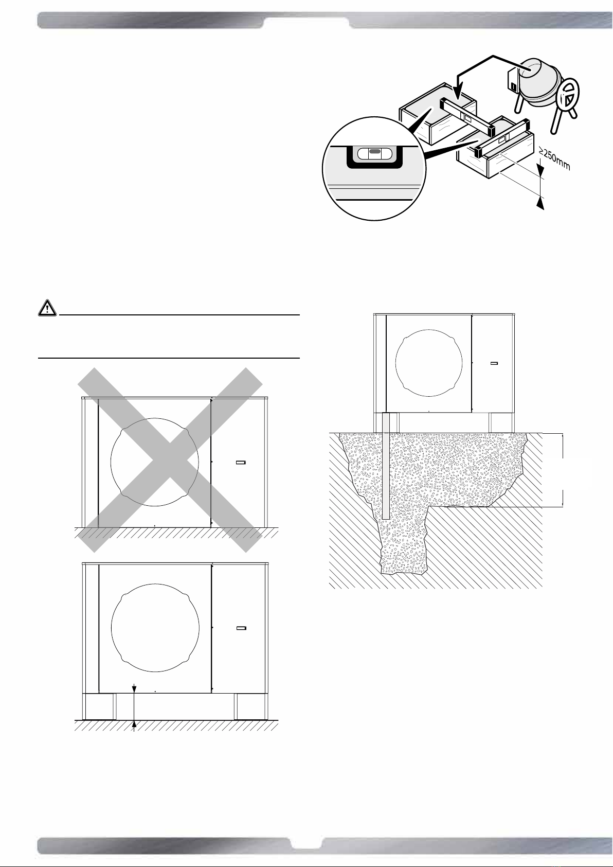
6.6
Condensatedischargepreparaon
The condensate is discharged behind the heat pump by a unique
way. Prepare the condensate discharge with a discharge pipe
or with a gravel bed.
WARNINGS!
Frost proof
depth
min 250mm
Frost
proof
depth
Frost proof
depth
min 250mm
Frost
proof
depth
Frost proof
depth
min 250mm
Frost
proof
depth
• Preparaon of the base for condensate drain
Frost proof
depth
min 250mm
Frost
proof
depth
depth
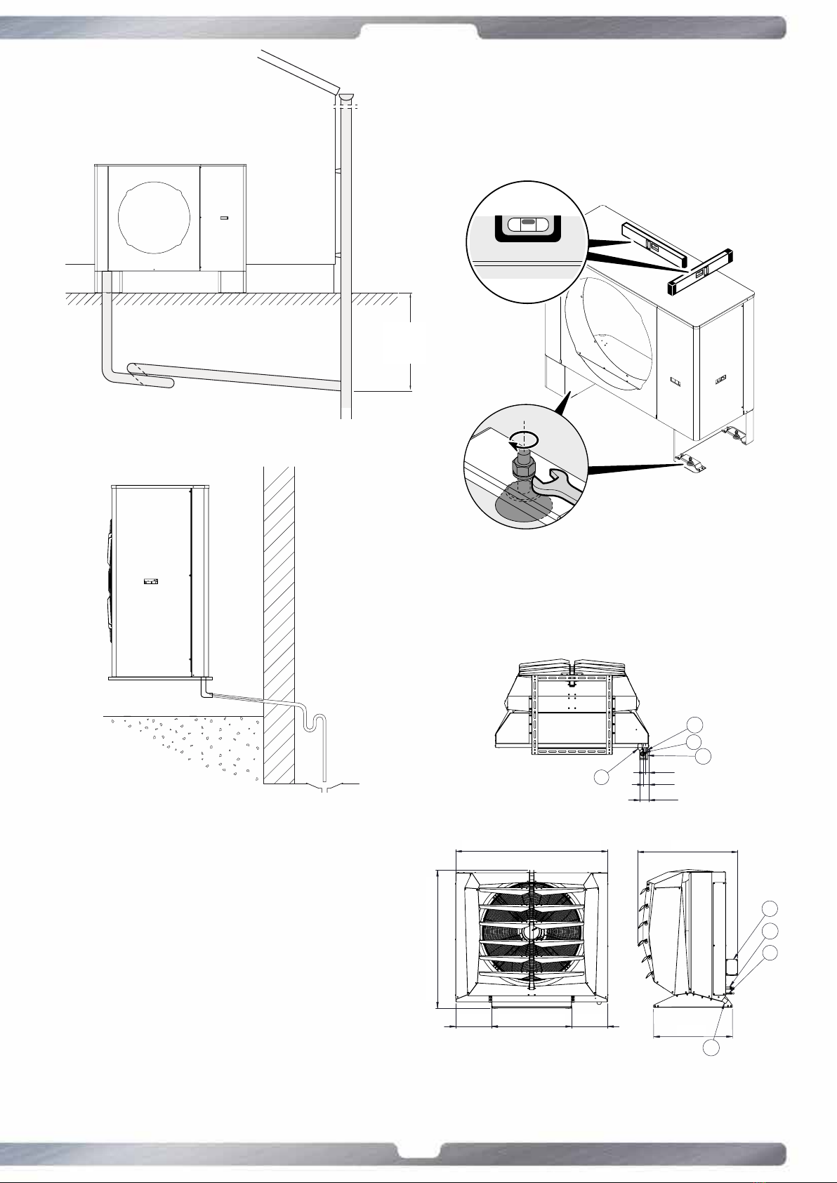
• Example 3 condensate drain (it is recommended to bury the
drain pipe to prevent the formaon of ice in the event that
you do not purchases oponally the heang resistor for
discharge condensate)
17
www.templari.com
Frost proof
depth
min 250mm
Frost
proof
depth
• Example 2 condensate drain
• Example 3 condensate drain with condensate drain element
the evaporator.
drain area.
6.7 Correct alignment
KITA AIR Templari® so that
7 Installaonandassemblyof
theinternalunit
7.1 InternalunitsizesKITAAIRR32
297 660 297
1139
1255
28
41
71
C
A
B
D
827
652
C
D
A
B
12 X 62
610
602
80
652
660
A
gas flow /
passaggio refrigerante (gas)
outer diameter /
diametro esterno:
22mm
B
liquid flow /
passaggio refrigerante (liquido)
outer diameter /
diametro esterno:
12mm
C
condensate drain /
scarico condensa
outer diameter /
diametro esterno:
40mm
D
electrical panel /
quadro ele�rico
BASE BRACKET /
BASAMENTO
DATE :
DRAWN BY :
DESCRIPTION:
TEMPLARI SRL - HEAT PUMP TECNOLOGY
Via Pitagora, 20A - 35030 Rubano (PD)
Tel. +39 049 5225929 - www.templari.com
G. Bacca
KITA AIR
INTERNAL UNIT
UNITA' INTERNA
INNENEINHEIT
12/04/2021
This drawing is the property of templari srl, any reproduction and/or distribution without templari srl approval is unlawful.
Il presente disegno è di proprietà di Templari Srl. La riproduzione totale e/o parziale e la divulgazione a terzi, senza nostro esplicito consenso scritto, verrà perseguita a norma di legge.
18
www.templari.com
7.2 Generaliesandchoiceofthe
installaonplace
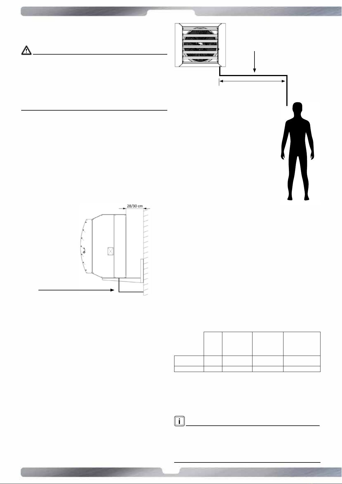
WARNING!
• Install the unit in an internal environment.
• The unit must not to be install near heat or steam sources.
from walls and obstacles for facilitate the assembly and
7.3 Assembly internal unit and correct
posioningofB2probe
be at least in two persons or more, as the excessive weight can
cause serious injuries.
the internal unit
the internal unit, it must alight at man height
with the wall because it is primary that the
the wall.
8 Refrigerant circuit
connecon
use of a weld tool.
8.1 Installaonrequirements
have to respect the below indicated dimensions.
at the base of the bigger piping. If the gap between the
internal and external unit is more than 5 m an u-trap at
medium height will be required.
Nominal
lenght Maximum lenght
of the piping
(m of equivalent
Maximum height
(m of equivalent
refrigerant charge
recommended*
(g/m of equivalent
54
NOTE!
The parameter equivalent lenght has to consider the curves too.
19
www.templari.com
8.2 Setupforinstallaonandrefrigerant
pipelinesinstallaon
• Measure the distance between internal and external units,
• The laying of the pipes must include the minimum number
of bends, because each curve increases the pressure drop
of the circuit and reduce the machine performance.
• Cut the pipes to a length slightly greater than that
measured.
the pipe downward and blowing air into the pipe.
the outer side male anchors. Where is possible, perform
minimum thickness of 6 mm.
WARNING!
Safety valve must be conveyed at a minimum distance of 5 m
8.3 Vacuum procedure
unit.
• At the end of the procedure remove the pump and open
the valve to pour out the refrigerant liquid.
WARNING!
it is recommended to adopt all the safety measures and use the
9 Maintenance and cleaning
and usury of the components. The user decides the maintenance
halfyearly.
polluted places or in the presence of dust that could
more frequent maintenance.
WARNING!
disconnect the power supply in order to avoid any injuries.
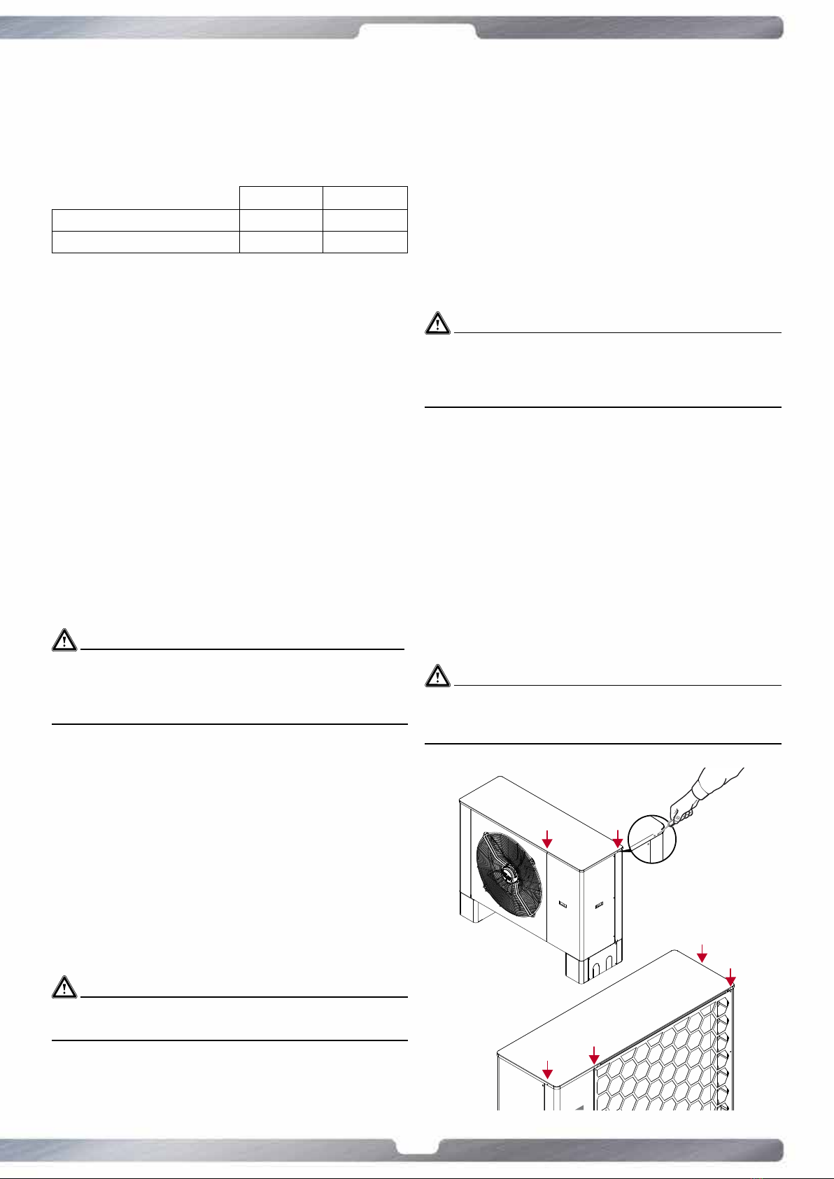
9.1 Finned coil cleaning
an adequate distance so as not to risk to fold or damage them.
• Clean the frontal surface;
placed in dusty ambient
WARNING!
service center.

20
www.templari.com
• Pass the power cables and the net control cable of the
machine only trough proper holes.
10.3 Externalunitconnecon
• Connect the power supply to the external unit electric
terminal by the following table named “power supply
apposite holes.
10.4 Internalunitconnecon
•
•
•
WARNING!
10.5 Probes and control panel
internal unit.
extend it, following the shortest path, away from powe cable
resistances that may interfer with the reading signal of the
control board.
the internal one by a bipolar cable.
The control panel gets connected to the external unit by a
6 metres telephonic cable supplied with the heat pump (on
10.6 Power supplying
Connect the power supply to the internal terminal block as
indicated in the diagram below.
9.2 Condensatedischargecleaning
Please make sure that the condensate discharge pipe is in the
9.3 Refrigerant circuit maintenance
The machine is equipped with a safety valve which ensure
and make sure to replace it each 4 years.
WARNING!
The triggering of the safety valve and the consequent expulsion
of the refrigerant gas may cause poisoning and injuries if in direct
contact with the skin.
Do not stand or place any heat source near the safety valve.
any servicing of the heat pump that requires welding.
10 Electricconnecon
10.1 Generalinformaon
make sure that the unit is in stable equilibrium and that there
•
•
• Make sure that upward the power supply line or the
pump requirements.
•
10.1.1Thecustomer/installerhasto:
breaker, CEI approved, as close as possible to the heat
pump, inside an adequate case
manufacturercannot be held liable for any damage caused
according to the layout of the electric wiring in the
10.2 Operaonsoflaying
• Avoid parallel laying with other cables, the arrangement is
Table of contents
Popular Air Conditioner manuals by other brands

Fujitsu
Fujitsu ASYG 09 LLCA installation manual

York
York HVHC 07-12DS Installation & owner's manual

Carrier
Carrier Fan Coil 42B Installation, operation and maintenance manual

intensity
intensity IDUFCI60KC-3 installation manual

Frigidaire
Frigidaire FAC064K7A2 Factory parts catalog

Sanyo
Sanyo KS2432 instruction manual


Mitsubishi Electric
Mitsubishi Electric PUHZ-RP50VHA4 Service manual

Panasonic
Panasonic CS-S18HKQ Service manual

Panasonic
Panasonic CS-E15NKE3 operating instructions

Gree
Gree GWH18TC-K3DNA1B/I Service manual

Friedrich
Friedrich ZoneAire Compact P08SA owner's manual

Daikin
Daikin R32 Split Series installation manual