Ten-Tec TITAN III 417 User manual

i
TABLE OF CONTENTS
TABLE OF CONTENTS
LIST OF ILLUSTRATIONS
SPECIFICATIONS
WARNING NOTICES
10 METER OPERATION
INTRODUCTION
UNPACKING
i-ii
iii-iv
v-vi
vii
vii
viii
ix
1INSTALLATION
1.1 INTRODUCTION
1.2 ELECTRICAL CONNECTIONS
1.3 HIGH VOLTAGE TRANSFORMER
INSTALLATION
1.4 TRANSCEIVER INTERCONNECTIONS
1.5 ANTENNA REQUIREMENTS
1.6 GROUND CONNECTION
1.7 HIGH POWER OPERATION
1.8 ALC
1.9 COOLING SYSTEM
1-1
1-1
1-1
1-2
1-2
1-2
1-2
1-3
1-3
2OPERATING INSTRUCTIONS
2.1 INTRODUCTION
2.2 FRONT PANEL CONTROLS
2.2.1 BAND SWITCH
2.2.2 TUNE
2.2.3 LOAD
2.2.4 POWER
2.2.5 OPR-STBY
2.2.6 QSK-PTT
2.2.7 MULTI-METER SWITCH
2.2.7.a Ep
2.2.7.b Is
2.2.7.c FWD
2.2.7.d REF
2.2.8 PLATE CURRENT METER
2.2.9 OVERDRIVE
2.2.10 WAIT
2.2.11 PEAK POWER BARGRAPH
2-1
2-1
2-1
2-1
2-1
2-1
2-1
2-1
2-1
2-1
2-1
2-2
2-2
2-2
2-2
2-2
2-2
2-2

ii
2.3 REAR PANEL CONNECTIONS AND CONTROLS
2.3.1 TRANSCEIVER
2.3.2 ANTENNA
2.3.3 KEY IN
2.3.4 KEY OUT
2.3.5 PTT/VOX
2.3.6 ALC
2.3.7 ALC CONTROL
2.3.8 AC LINE
2.3.9 LINE FUSES
2.4 INITIAL TURN-ON
2.5 TUNE – UP PROCEDURE
2.5.1 CHECKS TO MAKE BEFORE TUNING UP
2.5.2 IMPORTANT POINTS TO REMEMBER
2.5.3 SUGGESTED TUNE – UP PROCEDURE
3OPERATION AND SAFETY
3.1 INTRODUCTION
3.1.1 TUBES
3.1.2 INTERLOCKS
3.1.3 FUSES
4TROUBLESHOOTING
4.1 INTRODUCTION
4.2 MAINTENANCE
5CIRCUIT DESCRIPTIONS AND ILLUSTRATIONS
5.1 INTRODUCTION
5.2 INPUT MATCHING ASSEMBLY A6 (81946) AND 15M
FILTER ASSEMBLY A7 (81953)
5.3 HIGH VOLTAGE RECTIFIER ASSEMBLY A2 (81944)
5.4 SCREEN SUPPLY AND GRID BIAS ASSEMBLY A10
(81950)
5.5 QSK ASSEMBLY A11 (81949)
5.6 SWR ASSEMBLY A4 / RELAY A14 (81951 / 81959)
5.7 PLATE CONNECTOR ASSEMBLY A3 (81948)
5.8 METER/SWITCH/DISPLAY ASSEMBLIES A12 and
A13 (81947 and 81952)
5.9 HV-AC LINE INPUT ASSEMBLY A9 (81945)
5.10 LOAD SHUNT ASSEMBLY A5 (81943)
5.11 SCHEMATIC DIAGRAM, MODEL 417 AMPLIFIER
6MASTER PARTS LIST
2-2
2-2
2-2
2-2
2-2
2-2
2-3
2-3
2-3
2-3
2-3
2-3
2-3
2-3
2-4
3-1
3-1
3-1
3-1
4-1
4-1
5-1
5-1
5-1
5-3
5-4
5-6
5-8
5-9
5-10
5-12
5-14
5-15
6-1

iii
LIST OF ILLUSTRATIONS
FIG DESCRIPTION PAGE
1-1 T/R CONNECTIONS FOR TEN-TEC TRANSCEIVERS
WITH TX OUT AND TX EN
1-2 T/R CONNECTIONS FOR OTHER TRANSCEIVERS
2-1 MODEL 417 TUNING CHART
2-2 MODEL 417 TUNING LOG
2-3 MODEL 417 FRONT PANEL
2-4 MODEL 417 REAR PANEL
2-5 MODEL 417 TOP VIEW
2-6 MODEL 417 BOTTTOM VIEW
4-1 TROUBLESHOOTING HINTS
1-4
1-4
2-5
2-6
2-7
2-7
2-8
2-9
4-1
ASSEMBLY A6 (81946) INPUT MATCHING BOARD
5-1 CIRCUIT TRACE
5-2 COMPONENT LAYOUT
ASSEMBLY A2 (81950) H.V. POWER SUPPLY BOARD
5-3 CIRCUIT TRACE
5-4 COMPONENT LAYOUT
ASSEMBLY A10 (81950) SCREEN SPLY / GRID BIAS BOARD
5-5 COMPONENT LAYOUT
5-6 CIRCUIT TRACE
ASSEMBLY A11 (81949) QSK BOARD
5-7 COMPONENT LAYOUT
5-8 CIRCUIT TRACE
ASSEMBLY A4 (81951) SWR BOARD
5-9 CIRCUIT TRACE
5-10 COMPONENT LAYOUT
ASSEMBLY A3 (81948) PLATE CONNECTOR BOARD
5-11 CIRCUIT TRACE
5-12 COMPONENT LAYOUT
5-2
5-2
5-3
5-3
5-4
5-5
5-6
5-7
5-8
5-8
5-9
5-9

iv
ASSEMBLY A12 (81947) METER/SWITCH BOARD
5-13 COMPONENT LAYOUT
5-14 CIRCUIT TRACE
ASSEMBLY A13 (81952) DISPLAY BOARD
5-15 COMPONET LAYOUT & TOP CIRCUIT
5-16 BOTTOM CIRCUIT TRACE
ASSEMBLY A9 (81945) AC LINE / DELAY BOARD
5-17 COMPONENT LAYOUT
5-18 CIRCUIT TRACE
ASSEMBLY A5 (81943) LOAD SHUNT BOARD
5-19 CIRCUIT TRACE
5-20 COMPONENT LAYOUT
5-21 SCHEMATIC DIAGRAM, MODEL 417
5-10
5-11
5-10
5-12
5-12
5-13
5-14
5-14
5-15

v
SPECIFICATIONS
MODEL 417
BAND COVERAGE
POWER OUTPUT
DRIVING POWER
PLATE EFFICIENCY
INPUT AND OUTPUT
IMPEDANCE
HARMONICS
CW BREAK-IN
PROTECTIVE CIRCUITS
PRIMARY POWER
LINE PROTECTION
TUBES
COOLING
160, 80, 40, 30, 20, 17, and 15 meters
(12 and 10 meters for authorized users).
1500 watts continuous in SSB, CW, AMTOR/PACTOR
(50% duty cycle modes) on all bands. 1000 watts
RTTY/SSTV (continuous duty cycle modes) for up to 10
minutes on 160, 80, 40, 20, 15, and 10 meter bands (750
watts on WARC bands 30, 17, and 12 meters).
60 watts typical for 1500 watts output.
Up to 65% depending on band, frequency, line voltage
and impedance load.
50 ohms unbalanced with VSWR <2:1
Meets or exceeds FCC requirements.
Built-in T/R switching in less than 7 ms.
A.) Screen grid voltage regulation, current limiting, over
voltage protection and MOV arc over protection. LED
over-current indication.
B.) Control grid voltage regulation, current limiting and
LED over-current indication.
C.) Plate current over-current trip at 1.5 amps. Series
resistor for arc absorption.
240 VAC –10%/+5% @ 20 amps, 50/60 Hz
Primary line fuses, chassis interlock, and step-start inrush
protection.
Two Svetlana 4CX800A ceramic tetrodes in grid-driven
configuration.
Forced air, vertical exhaust, using centrifugal blower to
produce .1” of water pressure drop at sea level, 25 degs. C
air temperature.

vi
METERING
FRONT PANEL CONTROLS
STATUS INDICATORS
PLATE VOLTAGE SUPPLY
SCREEN SUPPLY
CONSTRUCTION
SIZE
WEIGHT
Full time plate current meter. Second meter selectable for
screen grid current, plate voltage, forward power, and
reflected power (x10). Peak forward power indicated on
full-time LED bargraph display.
TUNE and LOAD control knobs with 6:1 reduction drive.
Rotary band switch and meter switch for screen grid
current, plate voltage, forward or reverse power.
Standby / Operate , QSK / PTT-VOX and Power on/off
rocker switches.
Power on, wait, standby/operate, screen grid over-current,
control grid over-current.
Step-start inrush protected. Approximately 3000 VDC @
no load, approximately 2700 VDC @ full load.
6 amp, 1000 PIV diodes in fullwave bridge circuit. 9 each
220 uF electrolytic filter capacitors. 10 ohm arc
absorption resistor.
360 VDC voltage regulated, current limited.
.125” aluminum plate transformer and RF tank chassis.
.062” aluminum control / airbox chassis and covers.
HWD = 8.5" x 19" x 20"
(21.6 x 48.3 x 50.8 cm)
84 lbs. (38.18 kg)

vii
WARNING!!!!!!!
This amplifier contains lethal voltages when operating.
DO NOT operate this amplifier with the covers removed.
The power supply circuits in this amplifier can produce up to
3000 volts and cause serious injury or death!
CAUTION!!!
Never attempt to operate the TITAN III without first
connecting a suitable antenna or 50 ohm dummy load of
sufficient power rating or SERIOUS DAMAGE MAY
RESULT!
10 / 12 METER OPERATION OF THE TITAN III AMPLIFIER
FCC rules permit licensed amateurs to modify their own amplifiers for operation in
the 24.89 – 24.99 MHz and 28 - 29.7 MHz bands. If you enclose a copy of your
valid amateur radio license with the warranty registration card for your new
amplifier, an optional input matching circuit (assembly A8) and appropriate
installation information will be sent to you without charge.

viii
INTRODUCTION
The model 417 TITAN III is an advanced design linear amplifier using two
4CX800A high power tetrodes in a grid driven configuration. This amplifier uses
a ducted forced air cooling system and operates easily at 1500 watts output with
maximum efficiency of 65% .
Two panel meters provide system monitoring. One meter is dedicated to full
time plate current measurement. The other meter is switchable among plate
voltage, screen grid current, forward power, or reflected power.
Two front panel LEDs indicate overdrive conditions for the control grid and
screen grid circuits. Plate current overdrive trip is provided at 1.5 amps.
Band coverage includes 160, 80, 40, 30, 20, 17 and 15 meters as shipped from
the factory. With proof of authorization, 12 and 10 meters may be enabled with an
optional matching network from TEN-TEC.
Primary power of 240 VAC is required. Remember, tune-up at 1500 watts
output and 240 VAC line voltage can require up to 20 amps line current. The
TITAN III primary AC lines are fused at 20 amps. ABC-20 fuses or equivalent
must be used in replacement to protect the tubes. Interlocks on the high voltage
power supply are provided to ensure operator safety. NEVER DEFEAT THESE
SAFETY PRECAUTIONS !!!!

ix
UNPACKING
Carefully remove the amplifier from the packing carton and inspect it for signs of damage.
Carefully remove the high voltage power transformer from its’ packing carton and inspect it for
signs of damage. If the amplifier or transformer has been damaged, notify the delivering carrier
immediately, stating the full extent of the damage. Save all damaged cartons and packing
material. Liability for any shipping damage rests with the shipping carrier.
Complete the warranty registration form and mail to TEN-TEC immediately (include a copy of
your amateur radio license if you are requesting the 10 meter option). Save the packing material
for re-use in the event that moving, storage, or reshipment is necessary.
Shipment of your TITAN III in other than factory packing material may result in damage.
This is not covered under TEN-TEC warranty.
The following hardware and accessories are packed with your TITAN III. Make sure you have
not overlooked anything.
2 ea. 20 AMP ABC-20 fuses 27038
2 ea. 1
1
/
2
AMP MDL-1
1
/
2
fuses 27018
1 ea. key cable 46160
1 ea. .056 allen wrench 38040
1 ea. .062 allen wrench 38088
1 ea. # 8 allen wrench 38124
4 ea. #10 hex nuts 54005
(for plate transformer installation)
2 ea. 4x40 long black flathead screw 60039
24ea. 4x40 short black flathead screw 60080
(to finish installation of top cover)
1 ea. warranty card 74020
1 ea. operator’s manual 74367
2 ea spare 14” tube chimney clamp 38265
If any of the above are missing, contact the repair department at TEN-TEC for replacement.
Repair dept. (865) 428-0364
Switchboard (865) 453-7172
FAX (865) 428-4483
Before powering up your TITAN III, visually inspect the unit for possible physical damage,
such as dents or parts jarred loose during shipment. If you remove the top cover, remember that
safety interlocks on both line and high voltage prevent power up. Do not connect this amplifier
to AC power without the power transformer installed and the top cover securely held to the
chassis with the provided cabinet screws.

1-1
CHAPTER 1
INSTALLATION
1.1 INTRODUCTION: When setting up
the station, provide adequate ventilation for
the amplifier. Also, select a location that
allows comfortable access to the front
controls and adequate clearance for rear
panel connections.
1.2 ELECTRICAL CONNECTIONS:
The TITAN III amplifier draws up to 20
amps at 240 VAC. Care should be taken not
to overload house wiring circuits usually
fused or circuit breakered at 15 to 20 amps.
A straight run circuit with # 10 / 2 wire with
ground and breaker or fuses at 20 amps is
strongly advised. Do not connect the TITAN
III to AC voltage until installation of HV
power transformer is completed.
1.3 HIGH VOLTAGE TRANSFORMER
INSTALLATION: DO NOT CONNECT
THE AC LINE CORD TO 240 VAC WALL
OUTLET BEFORE INSTALLATION OF
THE HV POWER TRANSFORMER.
Check to make sure the amplifier is
unplugged from the wall. Remove the top
cover of the amplifier. Note only 8 screws
were initially installed at the factory. This
was done to simplify your task. Four of the
screws are in the underside bottom edges
(two long and two short). Temporarily
remove the left side chassis rail (four short
screws). There are four 10 x 32 nuts (TEN-
TEC part #54005) in the packing kit. You
must use these to mount the transformer and
not the nuts in the transformer shipping
carton. Identify the large open area in the
chassis where the transformer mounts.
Note the location of the four threaded studs
in the chassis. Start two nuts only on the
two studs closest to the center of the
amplifier chassis. Just “start” the two nuts,
engaging only a few threads. Orient the
transformer with the two wire HV lead side
of the transformer coil toward the center
chassis shield. Being careful not to disturb
the printed circuit board behind the meters,
align the slots in the transformer bottom
mounting bracket under the two nuts that
you just installed. Slide the transformer
toward the shield until the studs are seated in
the transformer mounting slots about
midway. Align the slots in the other bottom
mounting bracket with the two remaining
studs in the floor of the chassis near the
outside of the amp. Install the two
remaining nuts on the open studs. Using a
long nut driver or socket, tighten all four
nuts. Connect the two wire HV cable to the
socket on the HV rectifier board A2 (81944)
mounted on the center shield. Note the plug
will seat properly in the socket in one
direction only. Visually inspect the
connection for proper seating. Connect the
four wire primary cable to the four wire
cable extending from the rear chassis area
near the smaller low voltage transformer.
Again this plug will only seat properly in
one direction. Care should be taken when
re-installing the side rail and top cover not to
pinch this cable. Excess cable length may
be looped and tucked between the side rail
and fan housing scroll. Remember to install
all 34 screws in the top cover when re-
assembling. The extras you need are in the
packing kit. To access the five screws along
each bottom edge, carefully tilt the amplifier
on it’s side or slide it to the edge of the table
and work from below. Note that the front
two screws in each bottom edge are longer
than the rest (4 long screws total).
Never ship or transport the amplifier with
the transformer installed !!! Serious
damage to the chassis may result.

1-2
1.4 TRANSCEIVER
INTERCONNECTIONS: When using the
TITAN III with TEN-TEC transceivers with
TX EN and TX OUT connectors, follow the
diagram in Figure 1-1. The QSK-PTT/VOX
switch on the TITAN III should be in the
QSK position for all modes of operation.
This hook-up arrangement will work with
the OMNI series, PARAGON I and II,
PEGASUS, JUPITER, and ORION. Some
modern Yaesu transceivers are also
equipped with a full break-in keying loop
that can be utilized in a similar fashion. If
you are unsure about connecting this
equipment, please contact the TEN-TEC
factory for instructions.
When connecting the TITAN III with all
other transceivers, use the diagram in Figure
1-2. Note that the key or keyer must be
connected to the KEY IN jack on the
TITAN III, a cable is run from KEY OUT
to the key input jack on your transceiver,
and the line from the external T/R N.O.
relay contacts on the transceiver must be
connected to the PTT/QSK jack on the
TITAN III. When using this configuration,
the QSK-PTT/VOX switch on the amplifier
must be in the PTT/VOX position for SSB
operation and in the QSK position for CW
operation.
1.5 ANTENNA REQUIREMENTS:
The TITAN III amplifier is designed for use
with antennas resonant at the frequency of
operation and having an impedance within
the limit of 25 to 100 ohms, or an SWR of
2:1 or less (<10% reflected power). Note
that any SWR other than 1:1 will result in
TUNE and LOAD settings different from
those in the manual reference chart (Figure
2-1). The nominal load impedance of the
amplifier is 50 ohms. Antennas can exhibit
an SWR of more than 2:1 in some part of the
band. For operation under these conditions,
we recommend using an antenna matching
network that will enable the TITAN III to
work into a 50 ohm load for maximum
power transfer to the antenna.
1.6 GROUND CONNECTION: In the
interest of personal safety and to reduce the
possibility of stray RF pickup on
interconnecting cables, all station equipment
should be well grounded to earth and to
supply line ground bus. It is important to
strap all equipment chassis together with
short heavy leads. This ground bus may
then be tied to an external earth grounding
rod.
1.7 HIGH POWER OPERATION: The
TITAN III amplifier operates comfortably
at a maximum of 1500 watts output. New
owners often find that other components in
their station may not. Before operating at
this power level, be certain to check the
following items:
1. The coax from the TITAN III to the
feed point of your antenna must be
top quality RG-8 or better. We
recommend silver plated connectors
rather than chrome plated
connectors. Make sure that all coax
connectors are tight.
2. All coax switches or relays in the
feed line must be rated at 1500 watts
or higher. NEVER ACTIVATE IN-
LINE SWITCHES WHILE
TRANSMITTING.
3. Verify that the components in your
antennas are rated for the TITAN III
maximum power levels (dipole
center insulator, end insulators,
baluns, traps, etc.) Make sure that
all radiating sections are well clear
of metallic objects such as rain
gutters and antenna supporting
CAUTION!!!
Never attempt to operate the TITAN III
without first connecting a suitable
antenna or 50 ohm resistive load of
sufficient power rating or
SERIOUS DAMAGE MAY RESULT!

1-3
structures. For the first few hours of
operation, check the SWR
frequently. Any increase in
reflected power is an indication that
something between the amplifier and
the antenna elements, including the
end insulators, is heating and must
be corrected.
4. A solid earth ground is often
essential. Every station will have a
unique electrical ground due to
location of equipment, distance
between units, distance from house
wiring ground rod, distance from RF
ground rod, etc. Keep equipment
ground straps as short and thick as
possible and RF ground rod as close
to the station as possible.
5. If you use an antenna tuner, make all
SWR/matching adjustments with the
TITAN III in the STANDBY mode
using transceiver low power only.
6. If any of your home entertainment
electronic devices have RF leaks, the
TITAN III may find them. If you
are not familiar with standard
procedure for controlling this type of
interference, consult the ARRL
Radio Frequency Interference
Manual.
1.8 ALC: Most solid state transceivers do
not provide connection for ALC input and it
is unnecessary to make any external ALC
connection to these rigs. The ALC output
jack is used primarily with tube-type
transmitters or transceivers with a negative
going ALC system. The ALC ADJUST
control is used to set the threshold for proper
ALC action. This is -1 to -15 VDC
depending on input RF drive level. A
negative output voltage will be present at the
ALC jack only when the TITAN III is in the
OPERATE mode and the input RF drive is
above the threshold setting. Leave this
control fully clockwise if you have no
requirement for external ALC.
1.9 COOLING SYSTEM: The TITAN III
uses a pressurized cabinet with the main air
intake through the right front side of the
chassis and exhaust through the tube
chimneys on the right rear top of the
amplifier. It is safe to operate the amplifier
as long as there are no impediments to the
flow of air near the air intakes and/or the
exhaust.

1-4
TRANSCEIVER
FIGURE 1-2
T/R CONNECTIONS FOR OTHER
TRANCEIVERS WITHOUT TX OUT & TX EN
FIGURE 1-1
T/R CONNECTIONS FOR TEN-TEC
TRANCEIVERS WITH TX OUT & TX EN
TITAN III
TITAN III
TITAN III
TITAN III

2-1
CHAPTER 2
OPERATING INSTRUCTIONS
2.1 INTRODUCTION: The following
instructions will enable the operator to quickly
place the TITAN III in operation. Included are
descriptions of the front panel controls and rear
panel connections, followed by a detailed tune-
up procedure. Refer to Chapter 3 operation and
safety tips.
2.2 FRONT PANEL CONTROLS: The front
panel controls and their functions are described
below.
2.2.1 BAND SWITCH: This switch selects the
desired frequency of operation. This is an eight
position switch that covers the 160 meter to 10
meter bands. NOTE: A built-in switch stop
prevents operation in the 10 and 12 meter bands.
For 10 and 12 meter operation you must contact
the factory for an authorized modification kit.
30 meter operation is done in the 40B position,
17 meter operation in the 15 meter position, 12
meter operation in the 10 meter position.
2.2.2 TUNE: This control adjusts variable
capacitor C1 to provide resonance at the
operating frequency. Figure 2-1 shows the
approximate settings for both the TUNE and
LOAD controls on each band. Keep in mind
that the settings in this chart are for operation
into an ideal 50 ohm resistive load. There is
also a blank log chart that you may use to record
the actual control settings for your antennas.
2.2.3 LOAD: This control adjusts variable
capacitor C2 for the proper amplifier output
loading. See Figure 2-1.
2.2.4 POWER: This switch routes the AC line
to the primary of the low voltage supply. When
on, the TITAN III will power up and the
indicator light in the POWER switch will light.
2.2.5 OPERATE/STANDBY: This switch,
when in the OPERATE position, places the
amplifier online. When in the STANDBY
position, the amplifier is bypassed and only
the transceiver power is routed to the
antenna. When in the OPERATE position,
the indicator light in the switch will light.
NOTE: No high voltage will be read on the
metering when this switch is in STANDBY.
The OPERATE/STANDBY switch also
serves as the plate current trip-off circuit
reset switch. At 1.5 amps plate current, the
plate current trip-off circuitry will activate.
The lighted segment of the
OPERATE/STANDBY switch will go out
when plate current trip-off has occurred. To
reset, switch back to STANDBY and
immediately back to OPERATE. The
lighted segment of the switch should now be
lit again and the amplifier is ready to use.
2.2.6 QSK/PTT: This switch, when in the
QSK position, configures the key circuits for
CW/QSK operation. For late model TEN-
TEC transceivers with TX EN and TX OUT
connectors, or late model Yaesu transceivers
connected using a full break-in keying loop,
this position is used for all modes of
operation. Placing the switch in the PTT
position allows the TITAN III to be
controlled by the PTT/VOX input jack
rather than the KEY IN/KEY OUT loop.
2.2.7 MULTIMETER SWITCH: This
switch connects the right hand meter to
monitor various amplifier parameters.
A. Plate voltage (Ep) - When in this
position, the meter reads plate voltage.
This voltage is line voltage dependent
at a ratio of 12.5 V plate per 1 V line.
Plate voltage is approximately 3000
VDC at a line voltage of 240 VAC.
Therefore, at a line voltage of 250

2-2
VAC the meter will read a little higher
(3125 VDC).
B. Screen current (Is) - When in this position,
the meter is paralleled with a resistor in
series with the screen supply. This
monitors screen grid current. The upper
limit for screen current is 75 mA.
NEVER OPERATE THE TITAN III IN
EXCESS OF 75 mA SCREEN GRID
CURRENT. A warning zone indicator is
used on the face of the meter to alert the
operator. In addition to the analog meter,
the screen overdrive LED indicates
excessive screen current.
C. Forward power (FWD) - When in this
position, the meter is connected to the
forward port of a bridge circuit at the
antenna output. This measures forward
RF output power. It is, however, more
load dependent than an external
wattmeter. If your antenna is far from
resonance, the accuracy is not as good and
power measurements should be made
externally.
D. Reflected power (REF) - When in this
position, the meter is connected to the
reverse port of the bridge at the antenna
output. Reflected power is read at 1/10
indication scale of forward power (200
watts full scale).
2.2.8 PLATE CURRENT METER:
Full time plate current metering is provided
by the left analog meter.
2.2.9 OVERDRIVE: These two LEDs indicate
grid overdrive conditions.
A. When the screen overdrive LED is lit, the
screen current is approaching or has passed its
limit. Reduce drive from the transceiver
immediately and retune.
B. When the control grid overdrive LED is
lit, the control grid current is approaching or has
passed its limit. Reduce drive from the
transceiver immediately and retune.
2.2.10 WAIT: This LED indicates a 3 minute
warm-up period for the tube at initial power up.
After being turned on for 3 minutes, the wait
LED goes out and the TITAN III can be
placed in the operate mode.
2.2.11 PEAK POWER BARGRAPH:
This meter is connected to the bridge at the
antenna output through an emitter follower
to monitor peak RF output power. When the
red LED is lit, 1500 watts output has been
reached.
2.3 REAR PANEL CONNECTIONS
AND CONTROLS: The rear panel
connections and their functions are
described below.
2.3.1 TRANSCEIVER: This is a standard
SO-239 receptacle designed for a mating
PL-259 plug. RG-58U or similar 50 ohm
coax is required to connect the TITAN III to
the transceiver.
2.3.2 ANTENNA: This is a standard SO-
239 receptacle designed for a mating PL-259
plug. RG-8 or similar 50 ohm coax rated for
1500 watts is required for connection to the
antenna.
2.3.3 KEY IN: This jack is the input for
the TITAN III transmit/receive relay
system. When used with late model TEN-
TEC transceivers, this jack is connected to
the TX OUT connector on the transceiver.
When used with other transceivers, a key or
keyer is connected to this jack for CW
operation.
2.3.4 KEY OUT: This jack is a protected
output from the TITAN III which passes the
KEY IN to the transceiver after all relays in
the TITAN III have closed and it is ready to
transmit. When used with late model TEN-
TEC transceivers, this jack is connected to
the TX EN connector on the transceiver.
When used with other transceivers, this jack
is connected to the transceiver key input
jack.
2.3.5 PTT/VOX: This jack is an input to
the TITAN III transmit/receive relay

2-3
circuits. When used with late model TEN-TEC
transceivers, this jack is not used. When used
with other transceivers, this jack is connected to
the normally open (grounding) contacts of the
relay key out jack of the transceiver.
2.3.6 ALC: This jack provides a negative going
ALC voltage, used primarily with tube type
transmitters/transceivers. See section 1.8 for
detailed information.
2.3.7 ALC CONTROL: This control adjusts
the ALC threshold voltage from approximately -
1 to -15 VDC depending on RF input from the
transceiver.
2.3.8 AC LINE: This cable is connected to
standard 240 VAC. Be sure the line used to
power the TITAN III is capable of supplying 20
amps of current at 240 VAC, and that it is
protected by either fuses or circuit breakers of
20 amps. Wire size of the AC feed line should
be at least 10/2 with ground or larger.
2.3.9 LINE FUSES: Primary line fuses (ABC-
20) are accessible through these panel fuse
holders. Replace with ABC-20 or comparable
fuses only.
2.4 INITIAL TURN-ON: The following
steps should be followed when turning on your
TITAN III.
A. Set multimeter switch to the plate voltage
(Ep) position.
B. Place the power switch to ON. If any of
the following do not occur, press OFF at
once and investigate before proceeding.
1. The power switch light should light.
2. The meter lights should light.
3. The fan motor should start and air
flow should be felt at the exhaust port
on top of the amplifier.
4. The wait LED should light.
5. All meter indications are zero.
6. All other LEDs are not lit.
NOTE: HIGH VOLTAGE IS PRESENT ONLY
IN THE OPERATE MODE. THE OPERATE
MODE IS DISABLED FOR 3 MINUTES
WHILE THE WAIT LED IS LIT.
2.5 TUNE UP PROCEDURE: The
following section describes important points
to observe during tune up. A suggested
procedure for safely tuning up the TITAN
III is included.
2.5.1 CHECKS TO MAKE BEFORE
TUNING UP: Check the load connected to
the amplifier. This can best be done by
leaving the TITAN III in the BYPASS
mode and using only the transceiver output
power. Use a reliable SWR bridge or
wattmeter to determine the SWR of the load
(antenna) connected to the amplifier. If the
reflected power is less than 10% of the
forward power, the VSWR is less than 2:1.
If the reflected power is 4% or less, the
VSWR is 1.5:1 or lower. A VSWR of 2:1 or
less is essential.
2.5.2 IMPORTANT POINTS TO
REMEMBER: The most important
parameters to observe during tune up are the
control grid current and screen grid current.
Excessive grid current even for a relatively
short period of time can and will damage the
tube. If grid currents are not exceeded, the
4CX800A tubes will deliver many years of
trouble free service. In the TITAN III the
control grid is monitored by front panel
LED indicator. When control grid current is
exceeded, the GRID overdrive LED will
light. Reduce the drive immediately and
retune the TITAN III. Screen grid current is
monitored by the multimeter, (when in the Is
position) and by an LED overdrive indicator
continuously. Screen grid current should be
kept to a minimum during tune up and
always in a positive direction. When screen
current is exceeded the SCREEN overdrive
LED will light. Reduce drive immediately
and retune. After tune up, erratic lighting of
either overdrive indicator could indicate
breakdown in the load (antenna
components). Reduce drive and check for
arcing or heating of baluns, coax or other
elements. Brief blinks of the LEDs at initial
power-on or key-down are OK.

2-4
2.5.3 SUGGESTED TUNE UP
PROCEDURE: Following is the
recommended procedure for safe and proper
tune up of the TITAN III.
A. Set the band switch to the desired band.
For 30 meter operation, use position 40B.
For 17 meters, position 15. For 12
meters, position 10.
B. Set the multimeter switch to the Ep
position.
C. After the wait LED goes out, place the
STANDBY/OPERATE switch to
OPERATE. The STANDBY/ OPERATE
switch will light and high voltage is
indicated on the multimeter (nominal
3000 VDC).
D. Set the meter switch to the Is position.
Always monitor Is (screen grid current)
with the multimeter during tune up. Use
FWD and REF positions momentarily for
checking output power. Output power
can also be monitored on the LED
bargraph power meter. Always monitor
the overdrive LEDs. Reduce drive and re-
tune the amplifer if either is lit.
E. For initial tune up you may set the TUNE
and LOAD controls to their center
positions. Alternatively you may refer to
the suggested settings in the chart in
Figure 2-1. Keep in mind that these
settings are for operation into an ideal 50
ohm load and will vary with your
installation.
F. Turn the transceiver RF output control to
between 10 and 20 watts. Note: at very
low transceiver power outputs (<10 watts)
the amplifier may not respond when
attempting to tune up. This is normal.
Increase drive power slightly and continue
tune up. IF AT ANY TIME THE TITAN
III DOES NOT RESPOND AS
EXPECTED, REMOVE DRIVE POWER
IMMEDIATELY AND CORRECT THE
PROBLEM BEFORE CONTINUING.
G. Key the transceiver and slowly increase
the drive power until you see the plate
current increase.
H. Adjust the TUNE control for a peak in
screen grid current and a peak in RF
power output. Adjust the LOAD
control for minimum screen grid
current consistant with desired power
output. You will find that these values
are not always synchronized. Choose
the lower grid current adjustment even
if the power output is slightly less.
Readjust the TUNE control for a
screen grid current and power output
peak each time you adjust the LOAD
control. There will be some
interaction between these controls.
I. Gradually increase the drive level
from the transceiver until you reach
the desired output power level while
carefully touching up the LOAD and
TUNE controls for minimum screen
grid current and maximum output
power, respectively. NEVER
EXCEED 75 MILLIAMPS SCREEN
GRID CURRENT.
J. Once you have the amplifier tuned up
and operating on the desired
frequency, you can log the LOAD and
TUNE settings in the chart provided
(Figure 2-2). These settings should be
repeatable for the same frequency,
antenna, and SWR when used in the
future.

2-5
BAND FREQUENCY
MHz LOAD TUNE
160A
160B
1.820
1.980
6.1
4
4.1
5.5
80 / 75
3.500
3.980
8.7
5.5
7.5
4.7
40A
40B
7.040
10.120
3.6
2
1.6
1
20
14.050
14.250
1.5
1.4
1.5
1.1
15
18.110
21.050
2.1
1.4
5.2
1.5
12
10
24.900
28.100
2.5
1.6
4.2
.5
FIGURE 2-1 MODEL 417 TUNING CHART
FOR AN IDEAL 50 OHM LOAD

2-6
BAND FREQUENCY LOAD TUNE ANTENNA NOTES
FIGURE 2-2 MODEL 417 TUNING LOG
2-7
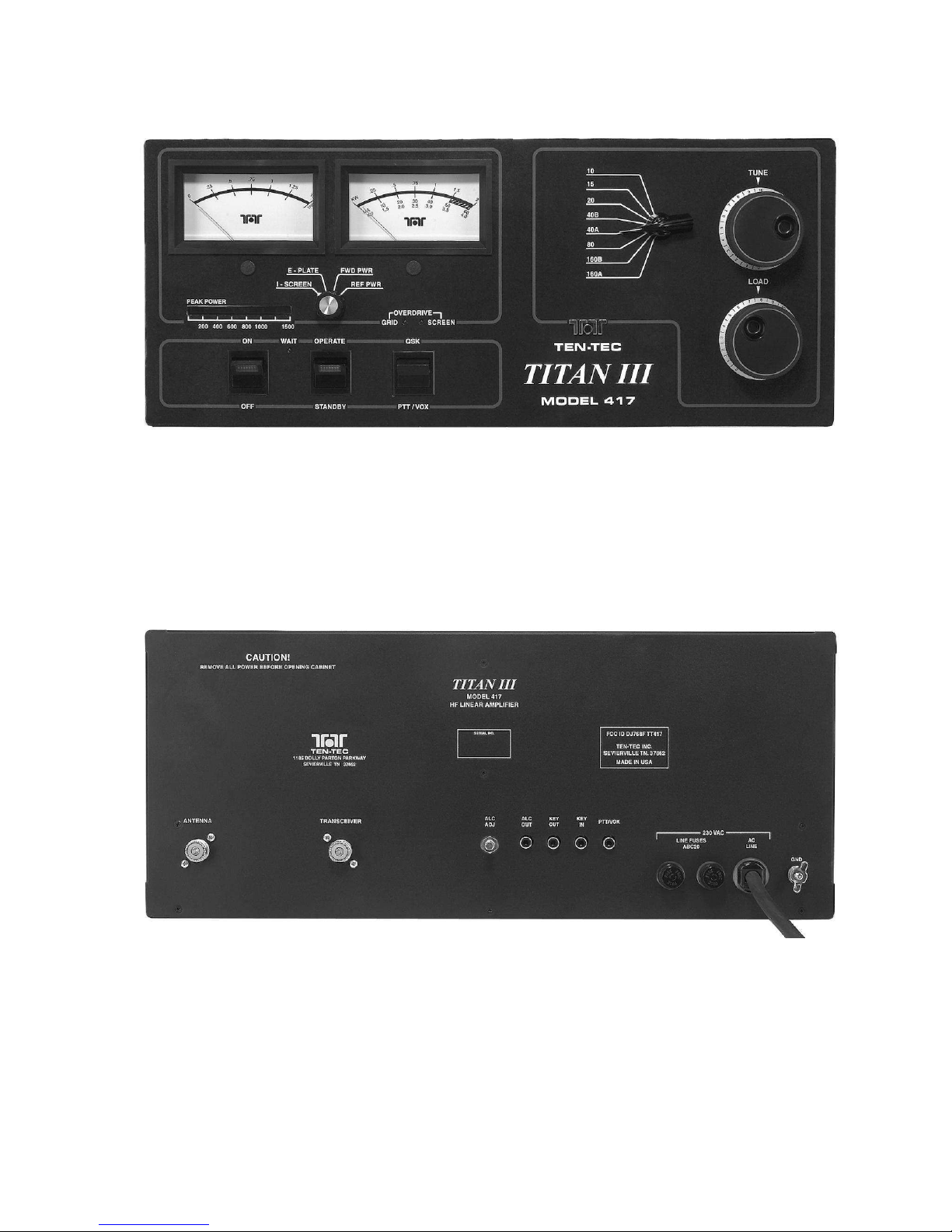
FIGURE 2-3 TITAN III FRONT VIEW
FIGURE 2-4 TITAN III REAR VIEW
Table of contents
Other Ten-Tec Amplifier manuals


