Tenpilot ECO 600 N User manual

Installation and user guide for the garage drive
for sectional and tilt-up doors.
ECO 600 N

Check other products of our brands on www.sukcesgroup.pl.

Table of contents:
1. Safety recomendations........................................................................4-5
2. Product description and features .......................................................5-6
3. Pre-Installation recommendations........................................................7
4.Montage..............................................................................................8-12
5. Programming instruction.................................................................12-15
6. Optional connectors and connections............................................15-16
7. Manual drive disconnection.................................................................17
8. Maintenance..........................................................................................17
9. Technical data..................................................................................18-19
10. Technical specications................................................................19-22
11. Common faults and solutions.......................................................22-24

4
Read the instructions carefully and follow all installation and safety
instructions.
Keep the instruction. Failure to follow these instructions can present risk to
life and health or damage to property.
Used electrical products should not be disposed of with municipal waste.
Throw them into specially marked containers.
1. Safety
1. The drive is designed and manufactured in accordance with applicable standards and
regulations.
To properly mount the drive, the installer must comply with the standards and
regulations in force in the country where the appliance will be installed.
2. Unskilled personnel or people who do not know the health and safety standards
applicable to the installation of automatic gates and doors may not under any
circumstances perform system installation or commissioning.
3. Persons who install or service the device without complying with all applicable safety
standards shall be liable for any damage, injury, costs, expenses or claims of the injured
person as a result of improper installation of the system.
4. In order to increase safety, we recommended to install the photocells. Although the
drive is equipped with an overload system, added of photocells will signicantly improve
the safety of automatic garage doors.
5. Before leaving or entering the garage, make sure that the garage door is completely
open and stationary.
6. After CLOSE command, make sure that the garage door is completely closed and
stationary.
7. Do not hold your hands near the drive and garage door when operating the drive.
8. The obstacle detection system is designed to work only on stationary objects. When
the garage door contacting with a moving object, it can cause serious personal injury
and / or property damage.
9. This device is not intended for use by children or persons with limited physical,
sensory or mental abilities, unless they have been supervised or trained in the use of the
device by a person responsible for their safety. Children should not play with the device.
10. If the supply cord is damaged it must be replaced by manufacturer, its service agent
or qualied persons in order to avoid a hazard.
11. Do not allow children to play garage door control units. Keep away remotes control
from children.
12. Watch the movable gate until it is fully opened or closed. Make sure there are no
people or animals nearby.
13. Be careful when opening the gate - an open gate that has damaged or weak springs

5
2. Drive description and functions
1. Obstacle detection
Drive stops or retreats if sensing resistance in its path. Thanks to this function, we can
protect children, pets and other things from being crushed by the gate.
2. Soft start / soft stop function
The reduced speed of moving the gate up and down at the beginning and end of each
cycle reduces the stress of the gate and drive to extend the service life and makes for
quieter working.
3. Auto closing
This function provides home security, automatically closing the gate after entering or
leaving the garage.
4. Automatic adjustable opening and closing forces
The drive force for various stages of gate movement is automatically set during the drive
conguration and is constantly updated. The drive force is automatically adjusted in the
appropriate range.
5. Electronic limit positions
Setting the electronic limit positions is quick and easy, you only need to control the con-
guration from the drive panel.
6. Additional connectors
Optionally, we can connect: photocells, additional receivers, wired and wireless wall swi-
tches, signal lamps and pass door protection.
7. LED lighting
The lighting switch on for each cycle for 3 minutes.
8. Connecting emergency power supply
In the event of a power failure, the drive can be powered from the battery.
may fall down sharply.
14. Check the installation regularly, especially wires, springs and mountings for signs of
use and damage. In a situation where it is necessary to repair or adjust the gate - do not
use it. Using an incorrectly balanced or damaged door can cause personal injury.
15. Once a month check obstacle detection function to work properly. Place an obstacle
with a height of min. 5 cm and close the gate - the drive should detect it and the gate
should stop or go back. If necessary, adjust the overload force and check again, as
improper adjustment can pose a hazard when using the door.
16. Familiarize yourself with the instructions before releasing and using the gate
manually.
17. Please check the informations of regulating the gate and drive.
18. Turn power supply off while cleaning or other maintenance.
19. The manual should contain details regarding the installation of the drive and related
components.

6
9. Break gear
The brake gear is a protection against uncontrolled lowering of the gate.
10. Disconnecting the drive manually
The manual release system is used to operate the gate in the event of a power failure.
11. Radio control
Rolling code technology (7.38 x 10 combinations), frequency 433.92 MHz, Transmitter,
eg 4-channel, allows you to control 4 gates using one transmitter.
12. The metal bottom plate provides a strong and safer assembly.
13. UP/DOWN control buttons.
19
GÓRA
DÓŁ
SET UP
CODE DOWN
Fig. 1

7
1. A correctly installed garage door should be manually lifted and closed without much
effort. Good balance of the gate and properly mounted springs are essential for proper
installation.
2. In a situation when the garage door is incorrectly mounted (opening of which requires
to use of large force), the drive should not be installed.
3. Make sure that mounted locking devices have been removed from the gate before
installing the device. In the opposite situation, you can lose your warranty.
4. The power supply socket must be mounted near the place where the drive will be
installed.
5. There should be a gap with a minimum height of 30 mm at its nearest point between
the bottom of the metal rail and the upper part of the garage door (Fig.2).
3. Pre-installation recommendations
As an additional protection for the garage door, we recommend installing
photocells on all installations.
Fig. 2
30 mm minimum
clearance

8
4. Montage
4.1 Installation of wall bracket and handle gate
4.2 Folding the rail
1. Wall bracket
Close the garage door, measure its width
at the top and mark the center. Attach and
mount the wall bracket on the inner wall
2cm-15cm above the gate (depending on
the space available).
2. Handle gate
Attach the handle door to the internal side
of the door as close as possible to the top
edge.
2- elements rail
3- elements rail
Fig. 3
Fig. 4
A:1500 mm
B:1500 mm
Łącznik
Rys.3
A: 1500 mm
B: 1500 mm
connector
Fig. 5
D:1000 mm
E:1000 mm
C:1000 mm
Łącznik
Rys.4
Łącznik
C: 1000 mm
D: 1000 mm
E: 1000 mm
connector
connector
9
4. Dokręć nakrę tkę, jak pokazano na rysunku 7,anastępnie przejdź do montażu szyny
Rys.6
Rys.7
Fig. 7 Fig. 8
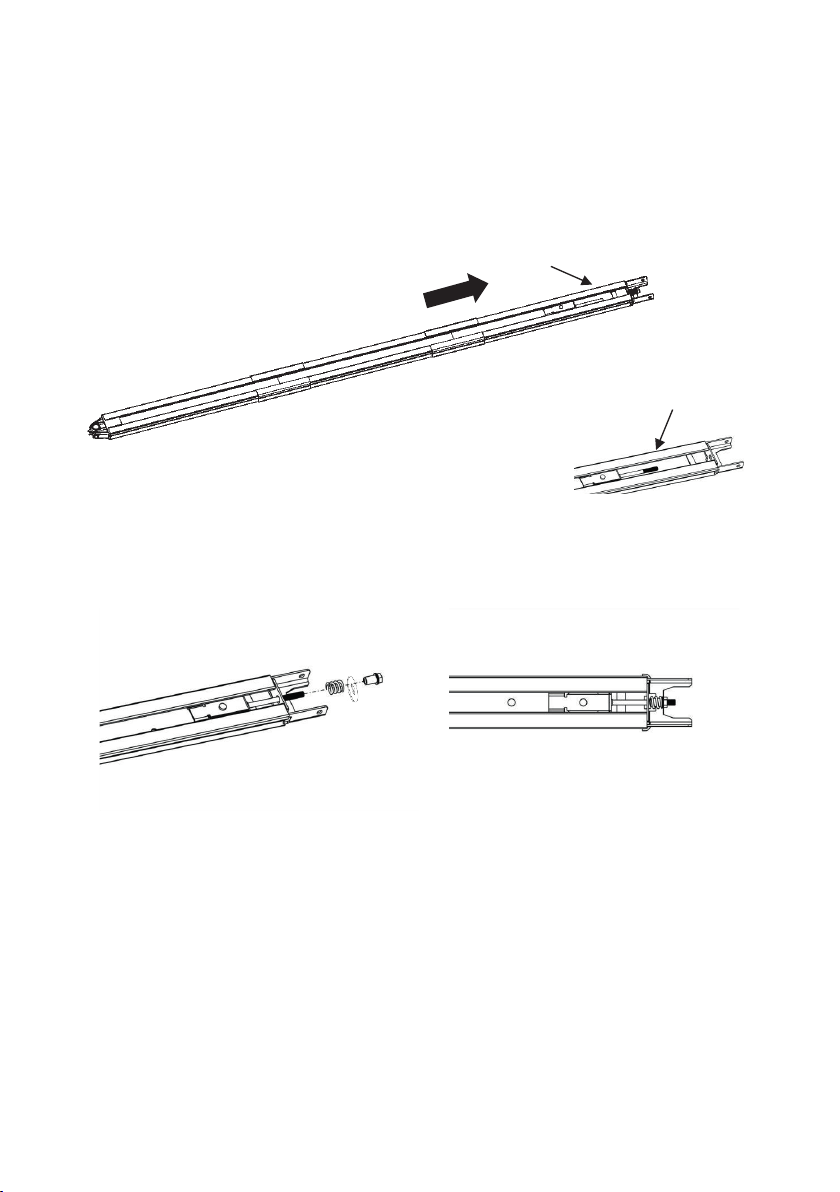
1. 2- elements rail:
Slide rail A and B in the connector (Fig. 4).
3- elements rail:
Slide the rail C, D and E into the connector (Fig. 5).
2. Pull the screw F with the tensioning element to the end of the rail (Fig. 6).
3. Loosen the nut and spring as in Fig. 7.
4. Tighten the nut as shown in Fig. 8, then go to the rail assembly.
Fig. 6
Rys.5
F
F

10
Fig. 9
4.3 Installation of a metal rail with a drive
STEP 1
Fasten the drive to the rail with two U-shaped handles. Fasten the handles with the 6 mm
nuts included in the set (Fig. 9).
STEP 2
Place the rail with a drive on the garage oor, in the middle of the gate. The side without
the drive should be at the gate. Lift and place the front of the rail in the wall bracket.
Insert the spindle and secure it with the cotter (Fig. 9).
STEP 3
Lift the rail with the drive so that it is position will be horizontal and in the center of the
gate. Mount the drive rail to the ceiling with mounting brackets (Fig. 9, Fig. 10).
STEP 4
Connect with screws the straight arm with the bented arm.
Place and screw the arms to the gate handle located on the upper edge of the gate, using
the screws included in the set (Fig. 9, Fig. 11).
Do not let children stay near a gate, drive or ladder. It can cause serious
injuries and / or damage.

11
4.4. Battery installation (optional)
STEP 5
Open the gate until the latch locks on the belt or chain, and proceed to the drive setting.
Option 1 - Mount at the top of the drive
Mount the battery using the handle and nuts (Fig. 12 i Fig. 13).
Option 2 - Mounting on the side of the drive
Mount the battery using the handle and nuts (see Fig.14 and 15).
Rys.9
Fig. 10
przykręć ramiona do uchwytu bramy na górnej krawędzi za
Rys.10
Fig. 11
Fig. 12 Fig. 13

12
Fig. 14
5. Programming
1. Press shortly UP or DOWN buttons to set precisely limit positions.
2. After setting the limit positions, the gate will automatically open and close.
During this time, the drive force is set. After the movement is completed, the
drive is ready for work.
5.1 Programming of limit positions
Press and hold SET button
untill digit 1 appear.
The drive is in programming mode.
Press and hold UP button
untill the gate will be in
its upper limit position.
Press and hold DOWN button untill the
gate will be in its lower limit position.
Press SET button to conrm
the upper limit position.
Digit 2 appears.
Press SET button to conrm
the lower limit position.
SET UP
CODE DOWN
SET UP
CODE DOWN
SET UP
CODE DOWN
SET UP
CODE DOWN
SET UP
CODE DOWN
Fig. 15

13
SET UP
CODE DOWN
SET UP
CODE DOWN
SET UP
CODE DOWN
5.2 Programming transmitters
5.3 Deleting programmed transmitters
5.4 Regulation of obstacle detection system
Press CODE button.
A dot will appear in the bottom corner.
Press button which will be control the gate
on the remote control. Wait 2 seconds,
press and hold the same button.
Dot will ash several times conrming
transmitter programmed.
Press UP button to increase or DOWN
button to decreases overload force.
Press and hold SET button untill digit 3
appear. The drive is in regulation overload
force mode. The minimum value of the
overload force is 1.
Press and hold CODE button untill C
symbol appear. All programmed
transmitters has been deleted.
Repeat the procedure for
all added transmitters.
Press SET button to conrm settings.
The default value of the overload
force is 3.
SET UP
CODE DOWN
The obstacle detection is set automatically during programming limit
positions. Typically, obstacle detection regulation is not necessary.
SET UP
CODE DOWN
SET UP
CODE DOWN

14
SET UP
CODE DOWN
SET UP
CODE DOWN
SET UP
CODE DOWN
SET UP
CODE DOWN
SET UP
CODE DOWN
5.5 Auto closing
5.6 Photocells
For the automatic closing function to work properly, photocells must be
installed.
Make sure that the photocells are properly connected. Use a NC photocell
(Fig. 15 and Fig. 16). The photocell function should be turned off when they
are not connected. Otherwise, it will not be possible to close the gate.
Press UP button to increase the time or
DOWN to decrease the time. The display
shows numbers from 0 to 9, where:
0 - auto closing function
is turned off,
1 - minimum closing time
it’s 15 seconds,
9 - maximum closing time
it’s 135 seconds.
Press the SET button
to conrm the settings.
Press DOWN button to turn on
the photocells. The digit 11 appear.
Press and hold UP button until the digit
or horizontal bar appears. Press UP button
again to set the automatic closing time.
Press UP button to activate photocells.
The „H” symbol appears in the display.
Press and hold DOWN button
untill digit 11 or symbol „H” appear.
Press the SET button
to conrm the settings.
SET UP
CODE DOWN
SET UP
CODE DOWN

15
The O / S / C input can be used to control the drive using an external switch.
The switch must have normally open voltage-free contacts (Fig. 19).
The power of the caution light should not exceed 25 W.
The external switch should be a „NO”.
5.7 Open/ stop/ close input
6. Optional connectors and connections
Connection of photocells - Fig. 17
Connection of the switch - Fig. 16
Fig. 16
GARAGE DRIVE
O/S/C
Fig. 17

16
Additional connectors:
1. The O / S / C input allows you to connect a switch to control the drive (Fig. 19).
2. The signal lamp (Fig. 18 and Fig. 19).
The drive has a separate output signal lamp. Supplying the signaling lamp it should be in
the 24 V - 28 V DC range and the current consumption must not exceed 100 mA. When
using AC 230 V signal lamps, additional relays should be used.
3. Pass door protection (Fig. 19).
This function does not allow the gate to be opened when the small wicket door is open.
Thanks to this, the door panel will not be damaged.
SD
AC 230 V
IN
FLASH LIGHT
(AC 230 V)
+24 PE PBGND GNDFLASH
Relay
Fig. 18
Fig. 19
GARAGE DRIVE
pass door
protection device caution light O/S/C
SD +24 PE PBGND GND

17
Rys. 20
Rys. 19
Konserwacja
Fig. 20 Fig. 21
7. Manual drive disconnection
The drive is equipped with a mechanism for disconnecting the drive, which allows you to
manually open or close the gate in the event of power failure or drive failure (Fig. 19). To
disconnect the drive, pull the handle. To re-engage the drive, simply close the latch of the
drive disconnect mechanism and then move the gate manually or start the drive until the
latch locks on the belt or chain.
In some cases, it is recommended to bring the drive disconnect handle to the outside so
that the mechanism is accessible from the outside (Fig. 21).
1. No special maintenance of the drive’s electronic system is required. Check at least
twice a year that the gate is properly balanced and that all working parts are in good con-
dition. Also check, at least twice a year, overload force and adjust it if necessary. Make
sure that the photocells, works correctly.
2. Bulb replacement:
Note: Before replacing the lighting, make sure that the power has been turned off and
that the voltage of the new bulb is compatible with its supply voltage and the power does
not exceed 25 W.
Loosen the screws on the lamp cover. Remove the lamp cover and then unscrew the old
LED lamp. Screw the new lighting LED and lamp cover.
8. Maintenance

18
9. ECO 600 N technical data
POWER 230 V | 50 Hz
MAX. PULLING FORCE 600 N
MAX. GATE AREA 10.0 m
MAX. GATE WEIGHT 80 kg
MAX. GATE HEIGHT 2400 - 3500 mm
RAIL chain | belt
OPENING SPEED 160 mm / sec.
LED LIGHT 24 V | 15 pcs. LED
LIMIT SWITCHES electronic
RADIO FREQUENCY 433.92 MHz
CODING FORMAT rolling code (7.38 x 10 combinations)
MEMORY 25 transmitters
LAMP CAUTION OUTPUT yes
OPERATING TEMPERATURE from -40°C to +50°C
SAFETY soft start and stop, the possibility of
connecting photocells and a caution lamp
PROTECTION DEGREE IP20
19
2

19
Max. gate area < 10.0 m Standard gate height: 2400 mm
Max. gate height: 3500 mm
2
10. Elements list
10.1 Table

20
NR
1
2
3
4
5
6
7
8
9
10
11
QUANTITY
1
1
1
1
1
1
1
1
1
1
1
Description
LED lighting housing
Electronic system 1
Electronic system 2
Housing
LED light
DC motor with gear
Motor shaft
Converter
Mounting the transformer
Steel bottom housing
Gearwheel
Table of contents
Popular Garage Door Opener manuals by other brands


Cornell
Cornell SGHNX-5011E Installation instructions and operation manual

Nexx Garage
Nexx Garage NXG-100 installation guide

Automatic Technology
Automatic Technology GDO-6v3 EasyRoller installation instructions

Wayne-Dalton
Wayne-Dalton 44 Double Flush manual

CAME
CAME 801XC-0120 quick start guide

Raynor
Raynor 87504RGD-267 manual

Raynor
Raynor COMMANDER 2000RGD owner's manual

TdA
TdA FBD180 Installation and user manual

Chamberlain
Chamberlain Model MotorLift 1000 owner's manual

Cardin Elettronica
Cardin Elettronica GL112409 Installation

Automatic Technology
Automatic Technology GDO-8 Shed Master owner's manual

Craftsman
Craftsman 139.18595 owner's manual