18
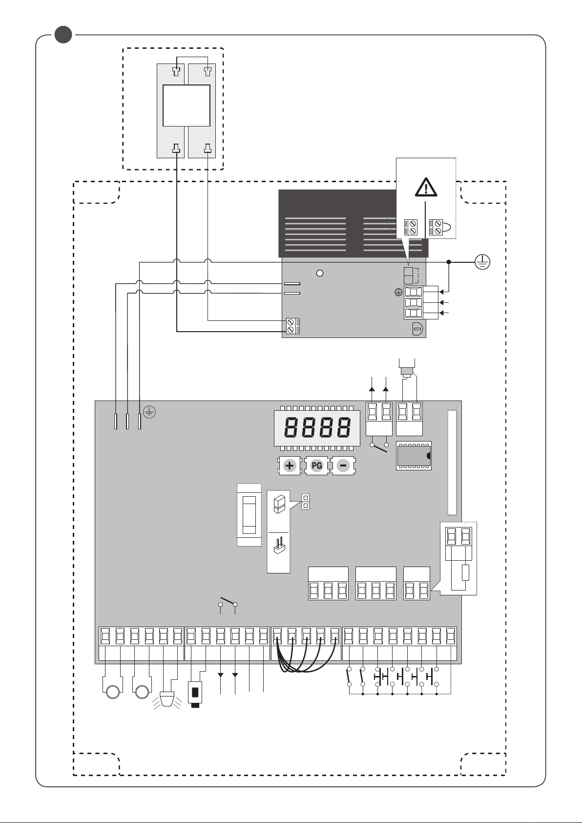
27 ENC1 Input Signal Encoder Motor 1
28 + Input + Encoder Motor 1
29 - Input - Encoder Motor 2
30 ENC2 Input Signal Encoder Motor 2
31 + Input + Encoder Motor 2
32-33
SENSITIVE
EDGE
(BAR)
Input, sensitive edge contact
Resistive edge: “BAR” Jumper closed
Mechanical edge: “BAR” Jumper open
When the edge is activated, the gate movement is stopped and reversed for about 3s.
34-35 AUX2
N.O. contact free from voltage can be configured via the AUX2 parameter as:
Open gate indicator (SCA), second radio channel (2nd CH), courtesy light (TLS), zone light, photocell
test contact (PHOTEST).
See parameter AUX2.
36-37 Antenna Connection to the built-in radio receiver card (30-signal/31-screen).
+ / - 24Vdc Input, 24VDC power supply.
U11 CONFIGURATION
MEMORY
Extractable Eprom Memory. Contains all the control unit configurations (logics, parameters, etc.), includ-
ing the radiotransmitters. In case of faults it is possible to extract Eprom and insert it into a different
control unit, avoiding reprogramming.
In case of replacement, it is imperative to respect the Eprom insertion direction.
The control unit is equipped with an built-in radio module for the reception of variable code controls with ARC (Advanced Rolling-Code), 433.92
MHz frequency.
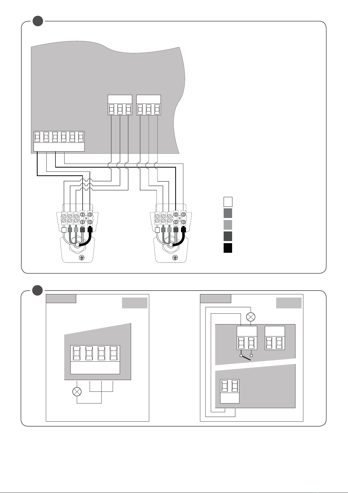
2) ENCODER WIRING
The HYBRA 24 central unit is to be used exclusively with the HD.3524/HD5024 series gear motors with encoder.
For connecting the encoder to the central unit, refer to Fig.2.
Although present, inputs for mechanical limit switches are not used.
3) AUTOSET
This function is used to set the optimal automation operating values and, at the end of the procedure, the parameters of DISPLACEMENT, WORKING
TIME and SLOWDOWN are adjusted.
Follow these steps to perform autoset:
1) Ensure that there are no obstacles in the door operating area, if necessary, cordon off the area to prevent access to people, animals, cars, etc.
During the autoset phase, the anti-crush function is not active.
2) Unlock the gear motors as indicated in the specific manual
3) Move both doors half way along the run and re-engage the gear motors.
3) Press the PG button, use the + button to select AUTO function and press OK.
4) The display shows the code HD24
5) Press OK to start the autoset phase.
6) The central unit performs a sequence of operations: single partial openings, full openings and closings at different speeds, and so on. D u r i n g
this phase, the display will show some acronyms that indicate the operation that is being performed at that time:
OPM1/2: motor 1 or 2 in opening phase
CLM1/2: motor 1 or 2 in closing phase.
If the motor movement is opposite to what is indicated on the display, stop the autoset by pressing any of the programming buttons, reverse the +/- wires
of the motor and repeat the autoset operation.
7) At the end of the autoset phase, the OK message is displayed.
Notes:
If the autoset is not successful, an ERR error message is displayed, refer to the Error Message table and proceed accordingly, and then repeat the
autoset operation.
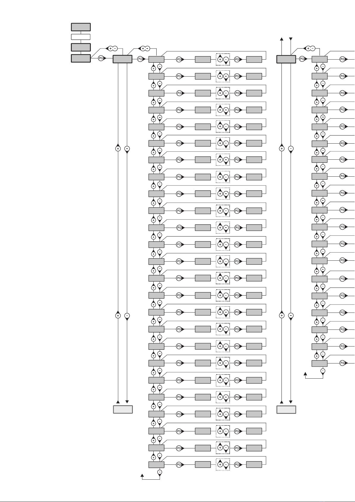
4) PROGRAMMING
The programming of the various functions of the control unit is carried out using the LCD display on the control unit and setting the desired values in
the programming menus described below.
The parameters menu allows you to assign a numerical value to a function, in the same way as a regulating trimmer.
The logic menu allows you to activate or deactivate a function, in the same way as setting a dip-switch.
Other special functions follow the parameters and logic menus and may vary depending on the type of control unit or the software release.
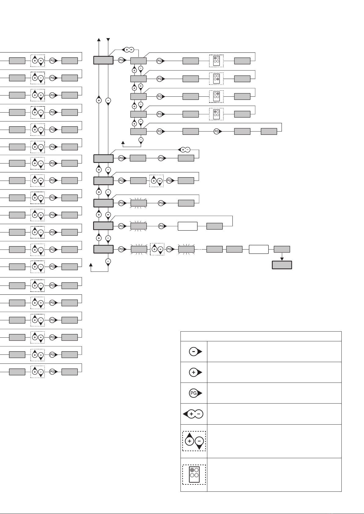
TO ACCESS PROGRAMMING:
1 – Press the button <PG>, the display goes to the first menu, Parameters “PAR”.
2 – With the <+> or <-> button, select the menu you want (PAR>LOG>RAD>NMAN>MACI>RES>AUTO>CODE).
3- Press the button <PG>, the display shows the first function available on the menu.
4 - With the <+> or <-> button, select the function you want.
5 - Press the button <PG>, the display shows the value currently set for the function selected.
6 - With the <+> or <-> button, select the value you intend to assign to the function.
7 - Press the button <PG>, the display shows the signal “PRG” which indicates that programming has been completed.
NOTES:
Simultaneously pressing <+> and <-> from inside a function menu allows you to return to the previous menu without making any changes. Hold down
the <+> key or the <-> key to accelerate the increase/decrease of the values.
After waiting 120s the control unit quits programming mode and switches off the display.
When the board is switched on, the software version is displayed for around 5 sec
Hold down the <+> key or the <-> key to accelerate the increase/decrease of the values.