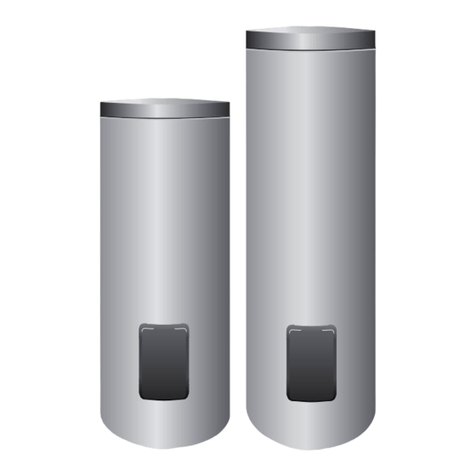
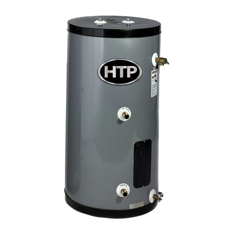
Termo TREND N Series User manual


EN
DEAR CUSTOMER
Thank you for selecting our product. The wiring, connection to the water supply and the first
commissioning must be carried out by a qualified expert with due attention to these instructions.
Information on fitting and operating must be carefully studied and the points raised must be observed
precisely. This will ensure that your appliance works reliable over the long term.
1. CONTENTS
The following accessories can be found in the box packaging
1 user guide
1 warranty card
1 service notes
1 combined safety valve
Please check these when receiving the appliance.
General instructions
1
A qualified expert must carry out the commissioning and initial start of the
appliance in strict compliance with the effective provisions and regulations
pertaining to commissioning, furthermore, in compliance with any criteria
determined by local authorities and public healthcare organizations.
2
Inasmuch as the hot water storage tank being commissioned is not merely
replacing an existing appliance, but it forms a part of the renewal of an
existing hydraulic system or a new hydraulic system, the water heater
commissioning company – having completed the commissioning – shall be
required to issue a statement of compliance to the customer, in which it
verifies compliance with effective legal regulations and specifications. In
both cases the company carrying out the commissioning must complete
safety and operational checks on the entire system.

EN
3
It is recommended to drain the appliance inasmuch as it is no
t in use in a
place subject to freezing temperatures. This operation must be carried out
by a qualified expert.
4 Running hot water above a temperature of 50 °C can cause serious burns.
5
This appliance can be used by children aged 8 years or older. The
appliance may be used by persons with reduced physical, sensory or
mental capacities, or those with lack of experience and knowledge, only in
the case where they are under appropriate supervision, or they have been
informed about the safe use of the appliance and they understand the
dangers therein. Children may not play with the appliance.
6
Children may clean the exterior of the appliance only when under
appropriate supervision.
7
Aside from the instructions given in the manual, any regular operation
carried out on the appliance – with the exception of maintenance that can
be carried out by the user – must be conducted by a qualified expert.
8
Only a qualified expert may remove the electric heating cover plate.
Failure to follow this instruction can result in an electric shock or other
hazard.
9
A qualified expert must carry out the commissioning and initial start of the
appliance in strict compliance with the effective national provisions
pertaining to commissioning, furthermore, in compliance with any criteria
determined by local authorities and public healthcare organizations. The
storage tank must be filled with water before turning on the heating.
10
Non
-
compliant commissioning can result in injury to persons and animals,
furthermore, it can cause damage to objects. The manufacturer bears no
liability whatsoever for these.
Follow and strictly comply with the general warnings and safety
instructions given in the abovementioned points.

EN
11
PUTTING THE STORAGE TANK AND HEAT EXCHANGER UNDER GREATER
PRESSURE THAN THE PERMITTED OPERATIONAL PRESSURE (0.7 MPa) IS
DANGEROUS AND FORBIDDEN. If the network pressure exceeds 0.6 MPs
even intermittently, a pressure reducing valve must be installed before the
hot water storage tank.
12
IT IS FORBIDDEN TO INSTALL A WATER SUPPLY ASSEMBLY BETWEEN THE
VALVE AND THE APPLIANCE.
13
CLOSING OFF THE DRAIN JOINT AND THE HIDDEN DRAINING OF THE
WATER OVERFLOW IS NOT PERMITTED.
14
IT IS FORBIDDEN TO OPERATE THE WATER HEATER WITHOUT A
PROTECTIVE EARTH.
15
HAVE THE FIRST HEATING CYCLE CHECKED BY AN EXPERT.
16
In order to guarantee safe operation, it is advised to occasionally
(approximately annually) have the correct operation of the appliance and
combined safety valve checked by a plumber. In addition, we recommend
that every month/two months the safety valve vent button should be
turned in the direction of the arrow in order to vent the valve. By doing
this it is possible to clean the valves from any possible accretions
(limescale, sand particles etc.).
17
It is forbidden to connect the appliance using a hose. Galvanized steel
piping, plastic piping and copper piping can be used for both hot and cold
water supplies. Insulating intermediates must be used for connecting
copper water supply piping to the network.
18
If the network connecting piping is damaged in any way, in order to rule
out danger it may be replaced only by the manufacturer, service centre
technicians or similarly qualified experts.

EN
19
Before carrying out any repair or maintenance the appliance must always
be turned off and the external switch turned to the ‘O’ (‘OFF’) position.
20
The storage tank may only be connected to the electricity supply with a
permanent connector. It is forbidden to use a wall plug.
21
Mains network electricity may only be connected
to the storage tank
through a double-pole switch where the distance between the open
contacts is at least 3 mm – this separation appliance must be built in to
the fixed network.
2. OPERATION
The unvented water heater is suitable for the supply of hot water to multiple outlets in households and
institutions.
The hot water is suitable for both washing and eating purposes.
The water is potable if it complies with the values given in Government Decree 201/2001. (X.25.). The
temperature of the water in the storage tank can be adjusted to your requirements (max. 70 °C). Once
the set temperature is reached, the thermostat automatically switches off the heating. Thus hot water can
be drawn from the storage tank for a long time. The polyurethane insulation surrounding the inner tank
stops the rapid cooling of water, thus ensuring that hot water can be drawn from the storage tank for a
long time. The storage tank is designed so that the hot water is drawn off without mixing.
The inner tank is made from corrosion-resistant sheet steel. The sheet steel is protected from corrosion
with a special enamelled finish and an active anode.
The enamelled finish also guarantees a long lifetime even in the case of aggressive (soft) water.
The main external dimensions of the appliance are shown in Figure 1.
3. FITTING INSTALLATION OF THE STORAGE TANK

EN
The fitting of the water heater and connection to the water and electricity networks must be done by an
expert in compliance with IEC 60364/HD 60364 provisions.
Before fitting, the wall structure must be examined by an architect.
We recommend the following solutions depending on wall type.
•Stone, brick, concrete wall 100-150 mm thick hexagonal bolts (M 12, EN ISO 4017), bolt washer
for wood connection (M 12).
Reinforced with 50 x 5 sheet steel horizontally on the rear of the wall.
•Thin walls hexagonal bolts (M 12, EN ISO 4017), bolt washer for wood connection (M 12).
Reinforced by installing two 60 x 40 x 3 U-steel (EN 10279) vertically on the rear of the wall.
4. CONNECTION TO THE WATER SUPPLY
Steel piping, plastic piping and copper piping or flexible pipe joints suitable to water pressure of 0.6 Mpa
can be used for both hot and cold water supplies.
Insulating intermediates must be used for connecting copper piping to the water supply.
One intermediate must be connected directly to the storage tank hot water pipe, the other to the cold
water pipe between the already installed fittings and the copper water supply. In the event of connections
without intermediates, we do not accept any guarantee for faults deriving from corrosion of the threaded
pipe ends of the storage tank, nor responsibility for damages therein. Intermediates not included.
The storage tank must be connected to the water supply as shown in Figure 2.
PUTTING THE STORAGE TANK UNDER GREATER PRESSURE THAN THE PERMITTED
OPERATIONAL PRESSURE IS DANGEROUS AND FORBIDDEN.
4.1 The combined safety valve is an accessory of the storage tank. Connection to the water heater and to
the water supply.

EN
The valve has to be mounted into the cold water pipe DIRECTLY in front of the storage tank, observing
the flow direction marked by an arrow. Before installing the valve, the cold water pipes have to be flushed
thoroughly in order to avoid damage caused by any possible contamination.
The outflow joint has to be placed vertically downwards and the vent button has to be accessible. In the
order of water flow there is the one-way valve, the security valve and the outflow pipe that has to be left
open toward the air.
4.2 If the network pressure exceeds 0.6 MPa even intermittently, a pressure reducing valve must be
installed before the water heater. This pressure reducing valve has to be purchased and mounted by the
customer.
The pressure reducing valve has to be mounted in front of the combined valve.
4.3 Any number of offshoots and mixing faucets can be connected to the storage tank. The backflow of
hot water via the faucet towards the water supply is blocked by a one-way valve. (Not a part of the water
heater).
4.4 The storage tank can be disconnected from the water supply using the closing valve.
5. ELECTRIC CONNECTION
5.1 The storage tank may only be connected to the electricity supply with a permanent connector. It is
forbidden to use a wall plug.
5.2 The mains electricity has to be connected to the storage tank through an all-pole disconnection
device, with a minimum 3 mm separation distance between the open contacts.
5.3 Required cross-section of mains network connection cabling 1.5 mm
2
– 2.5 mm
2
depending on the
performance shown in the table of data.
Cables suitable for connection to the network

EN
Suitable Alternative
H0 5 VVK (H0 5VVF)
H0 5 RRK (H0 5RRF)
H0 5 VVK (H0 5VVH)
Do not connect using a protective conduit.
5.4 The connecting wire has to be connected to the screwed connecting points of the thermostat/reducing
device.
5.5 The connecting wire has to be placed between the two clamps, then it has to be fixed to the sheath
base with fixing screws.
5.6 It is forbidden to operate the water heater without a protective earth. The protective earth must
comply with the provisions of IEC 60364.
6. COMMISSIONING
After installation, the storage tank can be put into operation. Have the first heating cycle checked by an
expert.
6.1 Open the closing valve (Figure 2., item No. 1) and the hot water faucet but keep the cold water faucet
closed. The water flowing in fills up the storage tank. In order to flush the unit, keep the water flowing for
a few minutes and then close it.
6.2 Connect the appliance to the mains electricity using the main switch. Use the thermostat to set the
desired temperature. During heating, the indicator light is on.
6.3 While heating, the expanding water may leak through the water outlet of the combined
safety valve, therefore this pipe has to be kept open toward the air.

EN
6.4 At the end of heating, when the temperature of the water reaches the value set, the thermostat
switches off automatically. After draining approximately 15% of the tank, the thermostat has to switch
back on automatically. If the thermostat does not switch on the heating automatically, please call the
repair service.
7. OPERATION AND MAINTENANCE
If a water leakage from the interior of the storage tank or any other abnormality is detected, immediately
disconnect the water heater from the water and electricity networks using the closing valve and the main
switch.
Leakage of the hot water faucet causes damaging overheating. It is in your interest to repair
the faucet.
7.1 Combined safety valve
With the storage tank in a cooled state, every two months the safety valve vent button should be turned
in the direction of the arrow in order to vent the valve. By doing this it is possible to clean the valve seat
from any possible accretions (limescale, sand particles etc.) and stop sticking. If water leakage does not
stop after switching off heating, the appliance must be examined by an expert; it is recommended to have
the storage tank checked every year in any case.
7.2 Thermostat and reducing device
The temperature of the water in the water heater can be regulated between 10 ºC – 70 ºC (at model 30L
up to 80 ºC) using the dial switch.
By turning the dial fully clockwise, the thermostat is set at zero position.
By turning the thermostat dial in an anticlockwise direction, the required temperature can be set
increasingly higher. Figure 4.
If the thermostat fails, the reducing device protects the water heater against damaging overheating by
breaking the heating electricity circuit before the water reaches a temperature of 100 ºC.

EN
The reducing device may be switched on again only by an expert after eliminating the cause of the
overheating.
7.3 Heating element
In case of failure, the heating element can be replaced after disconnecting the storage tank from the
mains and water networks, and draining the storage tank, then removing the screws on the cover.
Repairs must be carried out by a qualified expert.
7.4. Active anode
The water heater is equipped with an active anode to protect it against corrosion. The life expectancy of
the active anode depends on the water hardness and operational conditions. The state of the anode has to
be checked during periodic maintenance removing limescale, but
at least every second year
.
The date of the repeat check is set by the repair technician. If the diameter of the anode shrinks to 10
mm at any point, it has to be replaced.
Replacement can only be performed by a contracted service shop (see warranty).
After replacement of the active anode, its earthing has to be reset to its original state. It is
extremely important to ensure a good metal contact between the active anode and the
earthing screw.
IF THE ABOVE INSTRUCTIONS ARE IGNORED, RESULTING IN DAMAGE TO SAFETY AND USAGE
FEATURES OF THE APPLIANCE, YOU FORFEIT YOUR GUARANTEE AND WARRANTY RIGHTS.
7.5 Limescale removal
Limescale deposits form on the heating element and tank depending on the hardness of the water.
Limescale deposits on the heating element increase the probability of element failure, so it has to be
cleaned every second year.
The removal of limescale is considered to be a maintenance activity, it is not part of activities under
guarantee.

EN
As this activity requires opening the electric fittings, checks on the thermostat/reducing device, the
heating element and electric connections should also be performed at the same time.
THIS CHECK CAN ONLY BE PERFORMED BY A SERVICE SHOP
The necessity of cleaning the internal tank has to be checked when removing the mounted cover. During
cleaning, take care not to damage the protective coating.
7.6 Draining
Draining the storage tank can be performed by turning the combined safety valve vent button in the
direction indicated by the arrow, through the water outlet pipe. Before draining, the valve shutting off the
water network and the cold water faucet have to be closed, while the hot water faucet has to be kept
opened during draining.
7.7 Frost protection
Frost protection related to non-operation of the appliance (switching off power during winter) can only be
ensured if the tank is totally drained.
When the water heater is brought back into service, before it can be connected to the electricity supply it
must be filled with water.

EN
8. TECHNICAL DATA
QUALITY CERTIFICATION
Pursuant to BkM-IpM Decree
A2/1984 (III.10.), we hereby
declare that the appliance complies
with the following technical
characteristics
Applicable electric shock
protection electric shock
protection class I. Can be
connected to electricity network
supplied with protective earthing as
defined in IEC 60364. Main
regulations pertaining to the
product EN 60335-1, EN 60335-2-
21.
Storage and transporting criteria
EN 60721-3
TÍPUS TREND
30 N
TREND
50 N
TREND
80 N
TREND
100 N
TREND
120 N
TREND
150 N
TREND
200 N
Description Unvented water heater
Placement direction Wall mounted
Volume (l) 30 50 80 100 120 150 200
Voltage (V) 230~
Heating Power (W) 1600 1600 1800 1800 1800 2400 2400
Current (A) 7 7 7,9 7,9 10,5 10,5 10,5
Heat-up time from 15
ºC to 65 ºC (h)
1,16 1,2 1,9 2,8 4,2 5,2 5,2
Stand-by energie at
65ºC (Wh/24h) 0,83 0,933 1,42 1,51 1,91 2,38 2,75
Tube connections G1/2
Net mass(kg) 16,2 19,7 25,0 28,5 31,9 39,0 48,5
Nominal operation
preasurre (MPa) 0,6
Highest open
preasure point of
safety valve (MPa)
0,7
Built in safety
elements: Combined thermostat
Safety pressure valve
Other safety
elements: Active anode corrosion protection

EN
TÍPUS AQUA PLUS
30
AQUA PLUS
50
AQUA PLUS
80
AQUA PLUS
100
AQUA PLUS
120
AQUA PLUS
150
AQUA PLUS
200
Description Unvented water heater
Placement direction Wall mounted
Volume (l) 30 50 80 100 120 150 200
Voltage (V) 230~
Heating Power (W) 1600 1600 1800 1800 2400 2400 2400
Current (A) 7 7 7,9 7,9 10,5 10,5 10,5
Heat-up time from 15
ºC to 65 ºC (h)
1,16 1,2 1,9 2,8 4,2 5,2 5,2
Stand-by energie at
65ºC (Wh/24h) 0,83 0,933 1,42 1,51 1,91 2,38 2,75
Tube connections G1/2
Net mass(kg) 16,2 19,7 25,0 28,5 31,9 39,0 48,5
Nominal operation
preasurre (MPa) 0,6
Highest open
preasure point of
safety valve (MPa) 0,7
Built in safety
elements: Combined thermostat
Safety pressure valve
Other safety
elements: Active anode corrosion protection

CZ
MILÝ KUPUJÍCÍ!
Děkujeme, že jste si vybrali náš výrobek. Elektrické zapojení, připojení na vodovodní síť a první uvedení
do provozu nechte provést vhodnému odborníkovi, s přihlédnutím na tento manuál. Pečlivě si prostudujte
tento předpis, vztahující se k instalaci a použití, a přesně dodržujte věci v něm obsažené. Takto bude Váš
přístroj fungovat dlouhodobě spolehlivě.
1. PŘÍSLUŠENSTVÍ
V krabici balení se nachází následující příslušenství
1 návod k použití
1 záruční list
1 záruční podmínky
1 kombinovaný bezpečnostní ventil
Při přebírání přístroje buďte tak laskav a zkontrolujte úplnost balení!
Obecné pokyny
1
Kvalifikovaný odborník musí provést uvedení do provozu a počáteční start
spotřebiče v přísném souladu s platnými předpisy a předpisy týkající se
uvedení do provozu, dále v souladu se všemi kritérii stanovenými místních
orgánů a organizací veřejné zdravotní péče. Zásobník musí být naplněn
vodou před zapnutím topení.
2
Vzhledem k tomu, zá
sobník teplé vody právě uváděn do provozu je nejen
nahradí za stávající zařízení, ale je součástí obnovy stávajícího
hydraulického systému, nebo nového hydraulického systému, společnost
uvádějící ohřívač vody do provozu - po ukončení provozu - je povinna
vydat zákazníkovi prohlášení o shodě, ve kterém se ověřuje dodržování
platných právních předpisů a specifikací. V obou případech společnost
provádějící uvedení do provozu musí absolvovat bezpečnostní a provozní
kontroly na celý systém.

CZ
3
Je doporučeno vypu
stit spotřebič,
pokud není v provozu v místě
podléhajícím teplotám pod bodem mrazu. Tato operace musí být
provedena kvalifikovaným odborníkem.
4 Tekoucí teplá voda o teplotě nad 50°C může způsobit vážné popáleniny.
5
Tento přístroj může být použit děti o
d 8 let a staršími. Přístroj může být
používán osobami s omezenými fyzickými, smyslových nebo duševními
schopnostmi, nebo s nedostatkem zkušeností a znalostí, pouze v případě,
kdy jsou pod vhodným dohledem, nebo byli informováni o bezpečném
používání přístroje a chápou možnému nebezpečí. Děti se nesmí hrát se
spotřebičem.
6
Děti mohou čistit vnější části přístroje pouze tehdy, když jsou pod
vhodným dohledem.
7
Kromě pokynů uvedených v příručce, jakýkoliv pravidelná operace
probíhající na zařízení - s výjimkou údržby, která může být provedena
uživatelem - musí být prováděna kvalifikovaným odborníkem.
8
Pouze kvalifikovaný odborník může odstranit kryt elektrického topení.
Nedodržení tohoto pokynu může vést k úrazu elektrickým proudem nebo
jinému nebezpečí.
9
Nevyhovující uvedení do provozu může mít za následek zranění osob a
zvířat. Kromě toho může dojít k poškození zařízení a předmětů. Výrobce
nenese žádnou odpovědnost za tyto následky.
Je nutný postup a přísné dodržování pokynů v souladu s obecními
varováními a bezpečnostními pokyny uvedenými v tomto manuály.
10
ZAPOJENÍ ZÁSOBNÍKU A VÝMĚNÍKU NA VĚTŠÍ TLAK, NEŽ JE POVOLENÝ
PROVOZNÍ TLAK (0,7 MPa) JE NEBEZPEČNÉ A ZAKÁZANÉ. Pokud tlak v síti
přesahuje 0,6 MPa, i když přerušovaně, musí být nainstalován do
vodovodního systému redukční ventil před zásobníkem teplé vody.
11
JE ZAKÁZÁNO INSTALOVAT JAKÉKOLI VENTILY NEBO JINÁ ZAŘÍZENÍ
MEZI BEZPEČNOSTNÍM TLAKOVÝM VENTILEM A OHŘÍVAČEM VODY.

CZ
12
ZAVŘENÍ ODTOKOVÉHO OTVORU VENTILU NEBO ZAKRYTÍ VÝTOKOVÉ
TRUBIČKY DO ODPADU NENÍ POVOLENO.
13
JE ZAKÁZÁNO PROVOZOVAT OHŘÍVAČ VODY BEZ OCHRANNÉHO
UZEMNĚNÍ.
14
PRVNÍ OHŘÍVACÍ CYKLUS BY MĚL ZKONTROLOVAT ODBORNÍK.
15
V zájmu zajištění bezpečného provozu, doporučuje se čas od času
(přibližně jednou ročně) aby instalatér zkontroloval správnou funkčnost
spotřebiče a kombinovaného bezpečnostního ventilu. Kromě toho
doporučujeme, aby se jednou za měsíc pomocí páčky pojistného ventilu ve
směru šipky otevřel výpustný otvor ventilu tak, aby došlo k uvolnění
vzduchu. Tím dojde k pročištění ventilů a předchází se případnému usazení
vodního kamene, písku a různých částic.
16
Je zakázáno připojit přístroj pomocí hadice. Na připojení ohřívače může
být použito pozinkované ocelové potrubí, plastové potrubí a měděné
potrubí. Na vodovodní potrubí z mědi musí být použity izolační spojky.
17
Pokud je spojovací potrubní síť poškozena jakýmkoliv způsobem, aby bylo
vyloučeno nebezpečí, může být nahrazena pouze výrobcem, servisním
technikem nebo podobně kvalifikovaní odborníky.
18
Před prováděním jakékoli úpravy nebo údržby, zařízení musí být vždy
vypnuto a externí spínač otočen do polohy "O" ("OFF").
19
Zásobník může být připojen k přívodu elektřiny pouze s trvalým
konektorem. Je zakázáno používat elektrickou vidlici.
20
Hlavní elektrická síť může bý
t připojena k zásobníku pouze prostřednictvím
dvou- pólového přepínače, kde vzdálenost mezi otevřenými kontakty musí
být minimálně 3 mm - tento oddělený spotřebič musí být nainstalován do
pevné sítě.

CZ
2. FUNGOVÁNÍ
Nádrž s uzavřeným systémem je způsobilá na zásobování teplou vodou více míst pro odběr vody v
domácnostech a v institucích.
Získaná teplá voda je vhodná stejně na toaletní i stravovací cíle.
Voda má kvalitu pitné vody, pokud odpovídá mezním hodnotám uvedeným ve vládním nařízení. Teplotu
vody, nacházející se v nádrži je možné nastavit dle Vašich požadavků (na max. 70ºC). Po dosažení
nastavené teploty, tepelný regulátor automaticky vypne topení. Takto je možné z nádrže čerpat teplou
vodu po dlouhou dobu. Polyuretanová izolace kolem vnitřní nádrže zabrání rychlému vychladnutí vody,
takže je možné z nádrže čerpat teplou vodu po dlouhou dobu. Nádrž je vytvořena tak, že teplá voda
vychází bez pomíchání se.
Vnitřní nádrž je vyrobena z ocelové desky, chráněné proti korozi. Ocelovou desku vedle aktivního
žárového smaltování chrání před korozí i aktivní anoda.
Provedení ze žárového smaltu zajistí i v případě agresivních (měkkých) vod dlouhou životnost.
Hlavnější vnější rozměry zařízení jsou obsaženy na obrázku č. 1.
3. INSTALACE NAMONTOVÁNÍ NÁDRŽE
Namontování vodní nádrže, její napojení na vodovodní a elektrickou síť musí provést odborník podle
předpisů IEC 60364.
Před namontováním třeba se stavebním odborníkem prozkoumat konstrukci stěny.
U jednotlivých typů navrhujeme následující řešení.
•Kamenná, cihelná a betonová stěna o tloušťce 100-150 mm projíždějící šestihranné šrouby (M 12,
EN ISO 4017), podložka pro dřevěnou vazbu (M 12). Na zadní straně stěny posílení s plochou ocelí
50 x 5.

CZ
•Při velmi tenkých stěnách projíždějící šestihranné šrouby (M 12, EN ISO 4017), podložka pro
dřevěnou vazbu (M 12). Na zadní straně stěny posílení svislým zabudováním 2 ks 60 x 40 x 3 U
ocelemi (EN 10279).
4. NAPOJENÍ SE NA VODOVODNÍ SÍŤ
Jako vedení pro studenou a teplou vodu lze použít ocelovou troubu, umělohmotnou troubu a troubu z
červené mědi nebo pružné trubkové zalití, vhodné pro jmenovitý síťový vodní tlak 0,6 MPa.
Při napojení vodovodu z červené mědi je pro připojení povinné použití izolačních mezikusů!
Jeden mezikus je třeba namontovat přímo na vedení teplé vody nádrže, druhý mezi předem namontované
vedení studené vody armatury a vodovodní síť z červené mědi. V případě připojení bez mezikusu
neposkytujeme záruku na korozní vady závitových konců nádrže ani nepřijímáme odpovědnost za škody
vzniklé v důsledku toho. Montážní tvarovky nejsou v příslušenství.
Nádrž třeba připojit na vodovodní síť podle obrázku č. 2.
DRŽET NÁDRŽ POD VYŠŠÍM TLAKEM JAK JE POVOLEN PROVOZNÍ TLAK JE ŽIVOTU NEBEZPEČNÉ
A ZAKÁZÁNO.
4.1 Kombinovaný bezpečnostní ventil je součástí nádrže. Připojte ho k nádrži na teplou vodu a vodovodní
síti, s vnitřním závitem Rp1/2.
Ventil je třeba namontovat BEZPROSTŘEDNĚ před nádrž, do vedení studené vody, při zachování směru
proudění vyznačeném šipkou. Před zabudováním ventilu je nutné důkladně propláchnout vedení studené
vody, aby se předešlo případným škodám v důsledku nečistot.
Výtečné hrdlo musí spadat svisle dolů a vyfukovací tlačítko musí být přístupné. V pořadí proudění vody je
v něm zahrnut zpětný ventil a bezpečnostní ventil, jakož i vypouštěcí hadice, která musí být ponechána
otevřená směrem k vzduchovému prostoru (odpad)!

CZ
4.2 Pokud tlak v síti i jen dočasně překročí hodnotu 0,6 MPa, před nádrž na horkou vodu je nutno
zabudovat ventil na snížení tlaku. O jeho pořízení a montáž se musí postarat spotřebitel.
Ventil pro snížení tlaku musí být umístěn před kombinovaným ventilem.
4.3 Na nádrž lze napojit libovolné množství odboček a míchacích vodovodních baterií. Zpětnému proudění
teplé vody přes vodovodní baterii - směrem k vodovodní síti - zabraňuje zpětný ventil (není příslušenstvím
nádrže na horkou vodu).
4.4 Prostřednictvím uzavíracího ventilu lze nádrž odpojit od vodovodní sítě.
5. ELEKTRICKÉ PŘIPOJENÍ
5.1 Nádrž se smí do elektrického proudu zapojit pouze prostřednictvím připojení se stálou
charakteristikou. Je zakázáno použití nástěnné zástrčky!
5.2 Síťový proud se smí přivést k nádrži pouze přes vypínač, přerušující každou fázi, jehož vzdálenost
mezi otevřenými stykači je minimálně 3 mm.
5.3 Průřez potřebného síťového vedení 1,5 mm2 – 2,5 mm2 v závislosti na výkonu uvedeného v datové
tabulce.
Kabely, vhodné na síťové připojení
Vhodný typ Alternativní typ
H0 5 VVK (H0 5VVF)
H0 5 RRK (H0 5RRF)
H0 5 VVK (H0 5VVH)

CZ
Je zakázáno použít připojení v ochranné troubě!
5.4 Přípojné vedení třeba připojit na šroubové body tepelného regulátoru / omezovače.
5.5 Přípojné vedení třeba umístit mezi dvě svorky, následně ho třeba prostřednictvím upínacích šroubů
upevnit ke spodku pláště.
5.6 Je zakázáno provozovat nádrž na horkou vodu bez ochranného uzemnění! Ochranné uzemnění musí
splňovat předpisy normy IEC 60364.
6. UVEDENÍ DO PROVOZU
Po instalaci je možné nádrž spustit do provozu. Při prvním ohřívání správné fungování nechte zkontrolovat
odborníkovi.
6.1 Otevřete uzavírací ventil (Obrázek č. 2, položka 1.) a kohoutek na teplou vodu, ale kohoutek na
studenou vodu nechte uzavřen. Vtékající voda naplní nádrž. Kvůli proplachu nádrže nechte vodu téct
několik minut, následně ji uzavřete.
6.2 Přístroj zapojte do elektrické sítě prostřednictvím hlavního vypínače. Nastavte tlačítko regulátoru
teploty na požadovanou teplotu. Během zahřívání svítí kontrolka.
6.3 Během doby zahřívání může přes výpustní troubu kombinovaného ventilu kapat rozpínající
se voda, tuto troubu nechte otevřenou směrem do vzdušného prostoru.
6.4 Na konci ohřívací doby, kdy se voda zahřeje na nastavenou teplotu, se regulátor vypne. Po vypuštění
přibližně 15% vody se regulátor musí samostatně znovu zapnout. Pokud se nezapne ohřívání, je třeba
zavolat opraváře.
This manual suits for next models
19
Table of contents
Languages:
