terneo vt User manual

21 3
According to data from the internal temperature sensor,
the thermostat turns off the heating when the desired
temperature is reached and turns on when it decreases
by 1 °C.
terneo vt thermostat is designed to maintain constant
temperature from 0 to 35 ° in electric heating systems.С
WIRING
Load (connecting wires from heating element) is connected
to terminals 3 and 6.
Power voltage (230 V ± 10 %, 50 Hz) is supplied to
terminals 4 (neutral, N) and 5 (phase, L) .
Adjustment range
Input voltage
Weight in the complete set
Temperature sensor
Temperature hysteresis
16 А
3 000 АV
0 35... °С
2 0 10 %3 V ±
50 000 cycles
20 000 000 cycles
1 °С
0,18 10 %kg ±
IP20
7 7 35 × 5 × 9 mm
THE EFFECT OF INTERNAL HEATING
OF COMPONENTS ON TEMPERATURE
MEASUREMENT IS TAKEN INTO ACCOUNT
BY THE THERMOSTAT CORRECTION SYSTEM.
Be sure to enter data on the connected load power
in settings (Tab. 1). After a short-term voltage outage,
it may take some time to stabilize the measurements
(no more than 50 minutes).
SET THE LOAD POWER TO 100 W WHEN
CONTROLLED VIA CONTACTOR for correct
measurement of air temperature by thermostat.
Figure . Mounting the stat1 thermo
The is designed for indoor installation.
The ingress risk of moisture or liquid into the place
of installation must be minimized. When installed
in a bathroom, toilet, kitchen, swimming pool the
should be installed at the place out of reach of casual
spraying.
thermostat
thermostat
;
make a hole in the wall for box mounting and wall chase
for power wires and the sensor
The thermostat terminals are designed for a wire with
section not more than 2,5 mm . To reduce the mechanical
loads on the terminals it is desirable to use a soft wire.
The terminals should be tighten with torque 0 5 N m. Use
of aluminum is not desirable The sections of the wires,
which is connected to the stat, must be at least
copper 2 × 1,0 mm .
2
2
The wires are tightened in the terminals using
a screwdriver with a blade width no more than 3 mm.
, ·
.
thermo
The screwdriver with a blade width
more than 3 mm can cause mechanical damage to the
terminals. This may result in the loss of right for warranty.
It is important to remember that it is desirable to place the
on the inner wall of the room. It is recommended to store
out the thermostat of direct sunlight and drafts (Fig. 1).
stat fix the thermo in the mounting box.
perform the compounds according to the passport data;
To protect against short-circuit in the load circuit the circuit
breaker (CB) has to be installed before installing
the . The circuit breaker is installed in the gap
of phase conductor, as shown in the Wiring . It should
be designed for not more than 16 A.
thermostat
1
The ambient temperature during installation must
be between –5 ... + 45 °C. The installation height
of the should be in the range 0,4 1,7 m above
the floor level.
thermo ...stat
For installation you must:
;
take the power wires of the heating system
to the mounting box
It is necessary for the thermostat to switch the current to no
more than 2/3 of the maximum current specified in the
specification. If the current exceeds this value, the load
must be connected through a contactor (magnetic actuator,
power relay), which is optimized for this current (Wiring 2).
123
45
6
1
2
SSDCВ
L
РЕ
NL
N
N
N
1А1
А2 2 4
3
contactor
smart control of heating
vt
terneo
Technical datasheet
Installation and operating instructions
Thermostat, frame
Technical data sheet and
installation and operation manual
and warranty card
The packing box
1 piece
1 piece
1 piece
IN THE BOX
Number combinations under heat,
at least
Number of combinations without
heating, no less than
Degree of protection GOST14254
TECHNICAL DATA
Maximum load current
(for category AC-1)
Rated load capacity (for category AC-1)
Overall dimensions ( × × )w h d
NTC thermo-resistor
10 kOhm 25 °C (R10)
This will help to avoid possible danger, mistakes and
misunderstandings.
IMPORTANT. Before the installation and operation
dof the device, please read by the end of this ocument.
RELIABILITY OF THE POWER RELAY provides
protection against frequent switching in the
thermostat. If there was less than 1 minute between
relay switching, the relay activation will be delayed,
marking the countdown with a flashing dot.
NON-VOLATILE THERMOSTAT STORAGE
saves all settings in the event of a power outage.
THE STAT IS MOUNTED AND
CONNECTED after the installation and load testing
THERMO
Wiring . Connection of the circuit breaker and SSD 1
1234
5
6
1
2
SSDCВ
16 А
L
box with automatics
16 А
30 Аm
РЕ
230 V~ 50 Hz
load
zero
phasa
NL
N
N
N
SERVICE CENTER CONTACT:
+38 (091) 481-91-81
WhatsApp Viber Telegram
support@dse.com.ua
WARRANTY CARD
If you continue to have issues with the device, please
send it to a Service Center or to the store where you
purchased the device. If your device is defective due
to our fault, we will repair or replace it under warranty
within 14 business days.
The warranty for devices is valid for
from the date of sale, provided that the instructions
are followed. The warranty period for products without
a warranty certificate is counted from the date
of production.
terneo 36 months
If your device is not working properly, we recommend
that you first read the section «Possible problems».
If you cannot find an answer, contact Service Center.
In most cases, these actions resolve all issues.
Please see the full text of the warranty and the data you
need to send to your Service Center on the website
https://www.ds-electronics.com.ua/en/. If you have a
warranty case, please, contact the General distributor
in your area.
WARRANTY TERMS
serial №:
a seller, a seal:
place of a seal
date of sale:
an owner contact
for a service center:
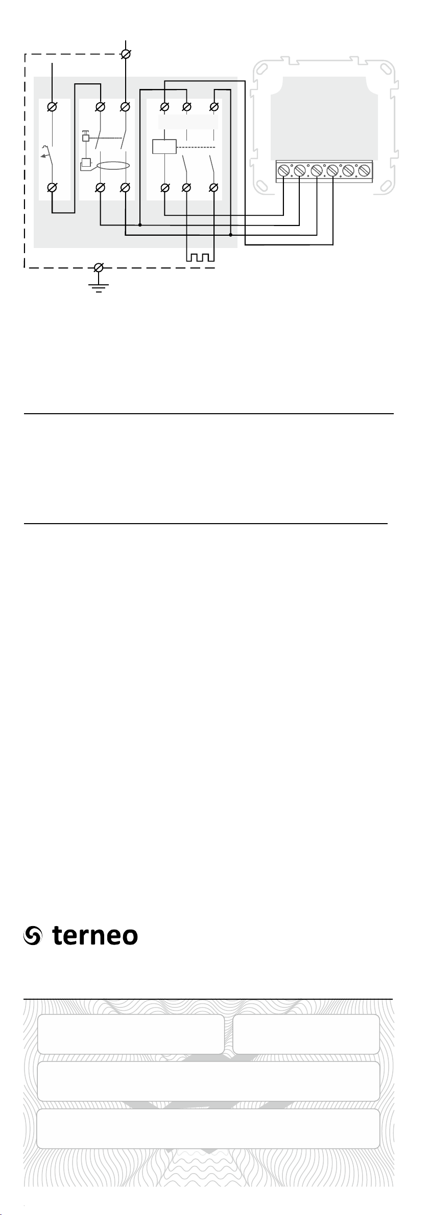
Wiring 2 Wiring and simplified internal circuit.
box with
automatics
230 V~ 50 Hz
load
zero
phasa
INSTALLATION

21 3
According to data from the internal temperature sensor,
the thermostat turns off the heating when the desired
temperature is reached and turns on when it decreases
by 1 °C.
terneo vt thermostat is designed to maintain constant
temperature from 0 to 35 ° in electric heating systems.С
WIRING
Load (connecting wires from heating element) is connected
to terminals 3 and 6.
Power voltage (230 V ± 10 %, 50 Hz) is supplied to
terminals 4 (neutral, N) and 5 (phase, L) .
Adjustment range
Input voltage
Weight in the complete set
Temperature sensor
Temperature hysteresis
16 А
3 000 АV
0 35... °С
2 0 10 %3 V ±
50 000 cycles
20 000 000 cycles
1 °С
0,18 10 %kg ±
IP20
7 7 35 × 5 × 9 mm
THE EFFECT OF INTERNAL HEATING
OF COMPONENTS ON TEMPERATURE
MEASUREMENT IS TAKEN INTO ACCOUNT
BY THE THERMOSTAT CORRECTION SYSTEM.
Be sure to enter data on the connected load power
in settings (Tab. 1). After a short-term voltage outage,
it may take some time to stabilize the measurements
(no more than 50 minutes).
SET THE LOAD POWER TO 100 W WHEN
CONTROLLED VIA CONTACTOR for correct
measurement of air temperature by thermostat.
Figure . Mounting the stat1 thermo
The is designed for indoor installation.
The ingress risk of moisture or liquid into the place
of installation must be minimized. When installed
in a bathroom, toilet, kitchen, swimming pool the
should be installed at the place out of reach of casual
spraying.
thermostat
thermostat
;
make a hole in the wall for box mounting and wall chase
for power wires and the sensor
The thermostat terminals are designed for a wire with
section not more than 2,5 mm . To reduce the mechanical
loads on the terminals it is desirable to use a soft wire.
The terminals should be tighten with torque 0 5 N m. Use
of aluminum is not desirable The sections of the wires,
which is connected to the stat, must be at least
copper 2 × 1,0 mm .
2
2
The wires are tightened in the terminals using
a screwdriver with a blade width no more than 3 mm.
, ·
.
thermo
The screwdriver with a blade width
more than 3 mm can cause mechanical damage to the
terminals. This may result in the loss of right for warranty.
It is important to remember that it is desirable to place the
on the inner wall of the room. It is recommended to store
out the thermostat of direct sunlight and drafts (Fig. 1).
stat fix the thermo in the mounting box.
perform the compounds according to the passport data;
To protect against short-circuit in the load circuit the circuit
breaker (CB) has to be installed before installing
the . The circuit breaker is installed in the gap
of phase conductor, as shown in the Wiring . It should
be designed for not more than 16 A.
thermostat
1
The ambient temperature during installation must
be between –5 ... + 45 °C. The installation height
of the should be in the range 0,4 1,7 m above
the floor level.
thermo ...stat
For installation you must:
;
take the power wires of the heating system
to the mounting box
It is necessary for the thermostat to switch the current to no
more than 2/3 of the maximum current specified in the
specification. If the current exceeds this value, the load
must be connected through a contactor (magnetic actuator,
power relay), which is optimized for this current (Wiring 2).
123
45
6
1
2
SSDCВ
L
РЕ
NL
N
N
N
1А1
А2 2 4
3
contactor
smart control of heating
vt
terneo
Technical datasheet
Installation and operating instructions
Thermostat, frame
Technical data sheet and
installation and operation manual
and warranty card
The packing box
1 piece
1 piece
1 piece
IN THE BOX
Number combinations under heat,
at least
Number of combinations without
heating, no less than
Degree of protection GOST14254
TECHNICAL DATA
Maximum load current
(for category AC-1)
Rated load capacity (for category AC-1)
Overall dimensions ( × × )w h d
NTC thermo-resistor
10 kOhm 25 °C (R10)
This will help to avoid possible danger, mistakes and
misunderstandings.
IMPORTANT. Before the installation and operation
dof the device, please read by the end of this ocument.
RELIABILITY OF THE POWER RELAY provides
protection against frequent switching in the
thermostat. If there was less than 1 minute between
relay switching, the relay activation will be delayed,
marking the countdown with a flashing dot.
NON-VOLATILE THERMOSTAT STORAGE
saves all settings in the event of a power outage.
THE STAT IS MOUNTED AND
CONNECTED after the installation and load testing
THERMO
Wiring . Connection of the circuit breaker and SSD 1
1234
5
6
1
2
SSDCВ
16 А
L
box with automatics
16 А
30 Аm
РЕ
230 V~ 50 Hz
load
zero
phasa
NL
N
N
N
SERVICE CENTER CONTACT:
+38 (091) 481-91-81
WhatsApp Viber Telegram
support@dse.com.ua
WARRANTY CARD
If you continue to have issues with the device, please
send it to a Service Center or to the store where you
purchased the device. If your device is defective due
to our fault, we will repair or replace it under warranty
within 14 business days.
The warranty for devices is valid for
from the date of sale, provided that the instructions
are followed. The warranty period for products without
a warranty certificate is counted from the date
of production.
terneo 36 months
If your device is not working properly, we recommend
that you first read the section «Possible problems».
If you cannot find an answer, contact Service Center.
In most cases, these actions resolve all issues.
Please see the full text of the warranty and the data you
need to send to your Service Center on the website
https://www.ds-electronics.com.ua/en/. If you have a
warranty case, please, contact the General distributor
in your area.
WARRANTY TERMS
serial №:
a seller, a seal:
place of a seal
date of sale:
an owner contact
for a service center:
Wiring 2 Wiring and simplified internal circuit.
box with
automatics
230 V~ 50 Hz
load
zero
phasa
INSTALLATION
21 3
According to data from the internal temperature sensor,
the thermostat turns off the heating when the desired
temperature is reached and turns on when it decreases
by 1 °C.
terneo vt thermostat is designed to maintain constant
temperature from 0 to 35 ° in electric heating systems.С
WIRING
Load (connecting wires from heating element) is connected
to terminals 3 and 6.
Power voltage (230 V ± 10 %, 50 Hz) is supplied to
terminals 4 (neutral, N) and 5 (phase, L) .
Adjustment range
Input voltage
Weight in the complete set
Temperature sensor
Temperature hysteresis
16 А
3 000 АV
0 35... °С
2 0 10 %3 V ±
50 000 cycles
20 000 000 cycles
1 °С
0,18 10 %kg ±
IP20
7 7 35 × 5 × 9 mm
THE EFFECT OF INTERNAL HEATING
OF COMPONENTS ON TEMPERATURE
MEASUREMENT IS TAKEN INTO ACCOUNT
BY THE THERMOSTAT CORRECTION SYSTEM.
Be sure to enter data on the connected load power
in settings (Tab. 1). After a short-term voltage outage,
it may take some time to stabilize the measurements
(no more than 50 minutes).
SET THE LOAD POWER TO 100 W WHEN
CONTROLLED VIA CONTACTOR for correct
measurement of air temperature by thermostat.
Figure . Mounting the stat1 thermo
The is designed for indoor installation.
The ingress risk of moisture or liquid into the place
of installation must be minimized. When installed
in a bathroom, toilet, kitchen, swimming pool the
should be installed at the place out of reach of casual
spraying.
thermostat
thermostat
;
make a hole in the wall for box mounting and wall chase
for power wires and the sensor
The thermostat terminals are designed for a wire with
section not more than 2,5 mm . To reduce the mechanical
loads on the terminals it is desirable to use a soft wire.
The terminals should be tighten with torque 0 5 N m. Use
of aluminum is not desirable The sections of the wires,
which is connected to the stat, must be at least
copper 2 × 1,0 mm .
2
2
The wires are tightened in the terminals using
a screwdriver with a blade width no more than 3 mm.
, ·
.
thermo
The screwdriver with a blade width
more than 3 mm can cause mechanical damage to the
terminals. This may result in the loss of right for warranty.
It is important to remember that it is desirable to place the
on the inner wall of the room. It is recommended to store
out the thermostat of direct sunlight and drafts (Fig. 1).
stat fix the thermo in the mounting box.
perform the compounds according to the passport data;
To protect against short-circuit in the load circuit the circuit
breaker (CB) has to be installed before installing
the . The circuit breaker is installed in the gap
of phase conductor, as shown in the Wiring . It should
be designed for not more than 16 A.
thermostat
1
The ambient temperature during installation must
be between –5 ... + 45 °C. The installation height
of the should be in the range 0,4 1,7 m above
the floor level.
thermo ...stat
For installation you must:
;
take the power wires of the heating system
to the mounting box
It is necessary for the thermostat to switch the current to no
more than 2/3 of the maximum current specified in the
specification. If the current exceeds this value, the load
must be connected through a contactor (magnetic actuator,
power relay), which is optimized for this current (Wiring 2).
123
45
6
1
2
SSDCВ
L
РЕ
NL
N
N
N
1А1
А2 2 4
3
contactor
smart control of heating
vt
terneo
Technical datasheet
Installation and operating instructions
Thermostat, frame
Technical data sheet and
installation and operation manual
and warranty card
The packing box
1 piece
1 piece
1 piece
IN THE BOX
Number combinations under heat,
at least
Number of combinations without
heating, no less than
Degree of protection GOST14254
TECHNICAL DATA
Maximum load current
(for category AC-1)
Rated load capacity (for category AC-1)
Overall dimensions ( × × )w h d
NTC thermo-resistor
10 kOhm 25 °C (R10)
This will help to avoid possible danger, mistakes and
misunderstandings.
IMPORTANT. Before the installation and operation
dof the device, please read by the end of this ocument.
RELIABILITY OF THE POWER RELAY provides
protection against frequent switching in the
thermostat. If there was less than 1 minute between
relay switching, the relay activation will be delayed,
marking the countdown with a flashing dot.
NON-VOLATILE THERMOSTAT STORAGE
saves all settings in the event of a power outage.
THE STAT IS MOUNTED AND
CONNECTED after the installation and load testing
THERMO
Wiring . Connection of the circuit breaker and SSD 1
1234
5
6
1
2
SSDCВ
16 А
L
box with automatics
16 А
30 Аm
РЕ
230 V~ 50 Hz
load
zero
phasa
NL
N
N
N
SERVICE CENTER CONTACT:
+38 (091) 481-91-81
WhatsApp Viber Telegram
WARRANTY CARD
If you continue to have issues with the device, please
send it to a Service Center or to the store where you
purchased the device. If your device is defective due
to our fault, we will repair or replace it under warranty
within 14 business days.
The warranty for devices is valid for
from the date of sale, provided that the instructions
are followed. The warranty period for products without
a warranty certificate is counted from the date
of production.
terneo 36 months
If your device is not working properly, we recommend
that you first read the section «Possible problems».
If you cannot find an answer, contact Service Center.
In most cases, these actions resolve all issues.
Please see the full text of the warranty and the data you
need to send to your Service Center on the website
https://www.ds-electronics.com.ua/en/. If you have a
warranty case, please, contact the General distributor
in your area.
WARRANTY TERMS
serial №:
a seller, a seal:
place of a seal
date of sale:
an owner contact
for a service center:
Wiring 2 Wiring and simplified internal circuit.
box with
automatics
230 V~ 50 Hz
load
zero
phasa
INSTALLATION

7
5 6
Preset temperature ( 25 °С)factory setting
When button or is pressed thermoregulator
switches to the mode of display and change of preset
temperature. While flashing, if button «+» is pressed
tpreset will be increased, if button «–» is pressed tpreset
will be decreased.
«–» «+»
Hold down button for a certain number of seconds
(see Table 1). Then change the parameter with the
and buttons. 3 seconds after the last pressing,
the thermostat will automatically return to the sensor
temperature display. In the waiting mode (when the
buttons aren`t currently being used) the brightness of the
indicator and the screen will be reduced to 30 %.
«–»
«+»
«–»
Switching to sleep mode
Hold down the « »
« »oFF
+ button for 4 seconds
(three dashes will appear on the screen one
after the other) until appears
on the screen. To turn it off completely, you
need to turn off the automatic switch.
Button blocking ( )
child and public protection
In order to enable disable button blocking
press the and buttons at the same
time for 6 seconds till the ( ) sign
appears on the screen.
+ –
/
« » « »
«Loc» «oFF»
To exit sleep mode, also hold the « »
« »on
+ button
for 4 seconds until appears
on the screen.
The temperature inside the housing exceeded
8 °C, the protection against internal
overheating worked.
5
Load is off, screen and indicator are off
Heating temperature does not correspond to
the settings
Possible cause: No power supply.
It is necessary: to check the tightening of power wires
in the terminals of the thermostat, make sure that
the switching load power does not exceed the permissible
one, the cross section of the wires for connection are
selected correctly.
Possible cause: load power is not correctly set.
It is necessary: make sure that the supply voltage is
available. If power supply is available, contact the Service
Center.
It is necessary: to correctly set the load power (Tab. 1).
If it is installed correctly, contact the Service Center.
The load does not work, the flashes on the
screen
ПРГ« »
Possible cause: internal overheating of the thermostat,
which can be caused by: poor contact in the terminals
of the thermostat, high ambient temperature, exceeding
the power of the switching load, or the cross section
of the wires for connection is incorrectly selected.
Features of the protection against internal overheating:
when the temperature inside the housing drops below
8 0 °C, the thermostat will resume operation. When
the protection is triggered more than 5 times in a row,
the thermostat will be blocked until the temperature inside
the housing drops below 0 °C and one of the buttons
is pressed.
8
Correction of screen reading
factory setting range( 0, ±5,0 °С,
0,1 °С)step
Firmware version
Load power setting
factory setting 2
0,1 – 3,0 , 0,1 )
1, kW( ,
range kW step kW
Resetting to
factory settings
6 sec
11 sec
9 sec
30 sec
The manufacturer reserves the right to modify the firmware
to enhance the device technical characteristics.
After releasing the button, the thermoregulator will reset
all settings to the factory settings and will reboot.
If necessary you can use the adjustment in the floor
temperature display on the thermostat screen.
Be sure to set the load power. The accuracy of
measurements depends on it.
Possible cause: is a break or short circuit of the
internal overheating sensor. Internal
overheating is not monitored.
Every 5 seconds the screen displays Ert« »
It is necessary: to send the thermostat to the service
center. Otherwise, overheating control will not be carried
out.
SET THE POWER OF THE CONNECTED LOAD
before its operation.
EXPLOITATION
vu11 11_2 201
Do not store the device and do not use it in areas with the
dust.
Turning on and off or and configure the device should be
with dry hands.
Never clean the device with the use of chemicals such as
benzene, solvents.
To protect against overvoltage caused by lightning
discharges, use a lightning protector.
Do not exceed the landmarks value adaptor and power.
Protect the children from games with the working device,
it is dangerous.
Avoid hitting of water or moisture to the device.
Do not expose the device to extreme temperatures
(higher than 40 ºС or below 5 °C) and high humidity.–
Do not connect the device to the network disassembled.
Do not switch the non assembled device to the network.
Do not attempt to disassemble and repair the device.
Carefully read and become aware of yourself these
instructions.
Connection of the device must be done by a qualified
electrician.
Do not connect 230 V mains voltage instead of the sensor
(it leads to failure of the thermostat).
Before the installation (dismantling) and connection
(disconnection) of the device, turn off voltage supply and
also act according to the «Rules of an arrangement of
electric installations».
Do not immerse the sensor with a connecting wire in the
liquid medium.
SAFETY INSTRUCTIONS
Low Voltage Directive 2014/35/E U
1 30 UEMC Directive 20 4/ /E
Manufacturer and vendor: DS ELECTRONICS, LTD
04136,
+38 (091) 1-91-8 , : +38 (091) 1-91-8
support@dse.com.ua www.ds-electronics.com.ua/en/
Ukraine, Kyiv region, Kyiv, 1–3 Pivnichno-Syretska str.
48 1 48 1Service Center
After the end of its service life, the product must be
disposed of in accordance with applicable law.
Transportation of goods carried in the package, ensuring
the safety of the product.
Do not fire and do not throw away the device with the
household waste.
If you have any questions or you something will not clear,
call the Service centre the telephone number listed below.
The device does not contain harmful substances.
The devi e is transported by any kind of transport (rail, sea,
motor, air transportation).
c
Date of manufacture is on the back side of device.
Application time is unlimited.
ADDITIONAL INFORMATION
POSSIBLE PROBLEMS, CAUSES
AND WAYS TO OVERCOME THEM
Menu section NotesScreenHold
« »≡
Table 1. FUNCTION MENU

7
5 6
Preset temperature ( 25 °С)factory setting
When button or is pressed thermoregulator
switches to the mode of display and change of preset
temperature. While flashing, if button «+» is pressed
tpreset will be increased, if button «–» is pressed tpreset
will be decreased.
«–» «+»
Hold down button for a certain number of seconds
(see Table 1). Then change the parameter with the
and buttons. 3 seconds after the last pressing,
the thermostat will automatically return to the sensor
temperature display. In the waiting mode (when the
buttons aren`t currently being used) the brightness of the
indicator and the screen will be reduced to 30 %.
«–»
«+»
«–»
Switching to sleep mode
Hold down the « »
« »oFF
+ button for 4 seconds
(three dashes will appear on the screen one
after the other) until appears
on the screen. To turn it off completely, you
need to turn off the automatic switch.
Button blocking ( )
child and public protection
In order to enable disable button blocking
press the and buttons at the same
time for 6 seconds till the ( ) sign
appears on the screen.
+ –
/
« » « »
«Loc» «oFF»
To exit sleep mode, also hold the « »
« »on
+ button
for 4 seconds until appears
on the screen.
The temperature inside the housing exceeded
8 °C, the protection against internal
overheating worked.
5
Load is off, screen and indicator are off
Heating temperature does not correspond to
the settings
Possible cause: No power supply.
It is necessary: to check the tightening of power wires
in the terminals of the thermostat, make sure that
the switching load power does not exceed the permissible
one, the cross section of the wires for connection are
selected correctly.
Possible cause: load power is not correctly set.
It is necessary: make sure that the supply voltage is
available. If power supply is available, contact the Service
Center.
It is necessary: to correctly set the load power (Tab. 1).
If it is installed correctly, contact the Service Center.
The load does not work, the flashes on the
screen
ПРГ« »
Possible cause: internal overheating of the thermostat,
which can be caused by: poor contact in the terminals
of the thermostat, high ambient temperature, exceeding
the power of the switching load, or the cross section
of the wires for connection is incorrectly selected.
Features of the protection against internal overheating:
when the temperature inside the housing drops below
8 0 °C, the thermostat will resume operation. When
the protection is triggered more than 5 times in a row,
the thermostat will be blocked until the temperature inside
the housing drops below 0 °C and one of the buttons
is pressed.
8
Correction of screen reading
factory setting range( 0, ±5,0 °С,
0,1 °С)step
Firmware version
Load power setting
factory setting 2
0,1 – 3,0 , 0,1 )
1, kW( ,
range kW step kW
Resetting to
factory settings
6 sec
11 sec
9 sec
30 sec
The manufacturer reserves the right to modify the firmware
to enhance the device technical characteristics.
After releasing the button, the thermoregulator will reset
all settings to the factory settings and will reboot.
If necessary you can use the adjustment in the floor
temperature display on the thermostat screen.
Be sure to set the load power. The accuracy of
measurements depends on it.
Possible cause: is a break or short circuit of the
internal overheating sensor. Internal
overheating is not monitored.
Every 5 seconds the screen displays Ert« »
It is necessary: to send the thermostat to the service
center. Otherwise, overheating control will not be carried
out.
SET THE POWER OF THE CONNECTED LOAD
before its operation.
EXPLOITATION
vu11 11_2 201
Do not store the device and do not use it in areas with the
dust.
Turning on and off or and configure the device should be
with dry hands.
Never clean the device with the use of chemicals such as
benzene, solvents.
To protect against overvoltage caused by lightning
discharges, use a lightning protector.
Do not exceed the landmarks value adaptor and power.
Protect the children from games with the working device,
it is dangerous.
Avoid hitting of water or moisture to the device.
Do not expose the device to extreme temperatures
(higher than 40 ºС or below 5 °C) and high humidity.–
Do not connect the device to the network disassembled.
Do not switch the non assembled device to the network.
Do not attempt to disassemble and repair the device.
Carefully read and become aware of yourself these
instructions.
Connection of the device must be done by a qualified
electrician.
Do not connect 230 V mains voltage instead of the sensor
(it leads to failure of the thermostat).
Before the installation (dismantling) and connection
(disconnection) of the device, turn off voltage supply and
also act according to the «Rules of an arrangement of
electric installations».
Do not immerse the sensor with a connecting wire in the
liquid medium.
SAFETY INSTRUCTIONS
Low Voltage Directive 2014/35/E U
1 30 UEMC Directive 20 4/ /E
Manufacturer and vendor: DS ELECTRONICS, LTD
04136,
+38 (091) 1-91-8 , : +38 (091) 1-91-8
[email protected] www.ds-electronics.com.ua/en/
Ukraine, Kyiv region, Kyiv, 1–3 Pivnichno-Syretska str.
48 1 48 1Service Center
After the end of its service life, the product must be
disposed of in accordance with applicable law.
Transportation of goods carried in the package, ensuring
the safety of the product.
Do not fire and do not throw away the device with the
household waste.
If you have any questions or you something will not clear,
call the Service centre the telephone number listed below.
The device does not contain harmful substances.
The devi e is transported by any kind of transport (rail, sea,
motor, air transportation).
c
Date of manufacture is on the back side of device.
Application time is unlimited.
ADDITIONAL INFORMATION
POSSIBLE PROBLEMS, CAUSES
AND WAYS TO OVERCOME THEM
Menu section NotesScreenHold
« »≡
Table 1. FUNCTION MENU
Table of contents
Other terneo Thermostat manuals


Popular Thermostat manuals by other brands

Peco
Peco T8000 series installation guide

Pro1 Technologies
Pro1 Technologies T721i Product installation guide

PSG
PSG HS-4024U Installation and operating instructions

Daikin
Daikin DT4272 Owner's manual & installation guide

ELEKTRA
ELEKTRA MWD5-1999 user manual

White Rodgers
White Rodgers 1F78 installation instructions


