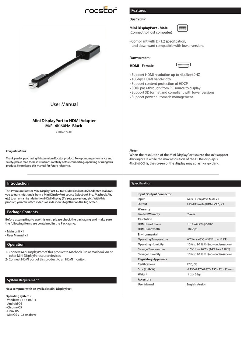
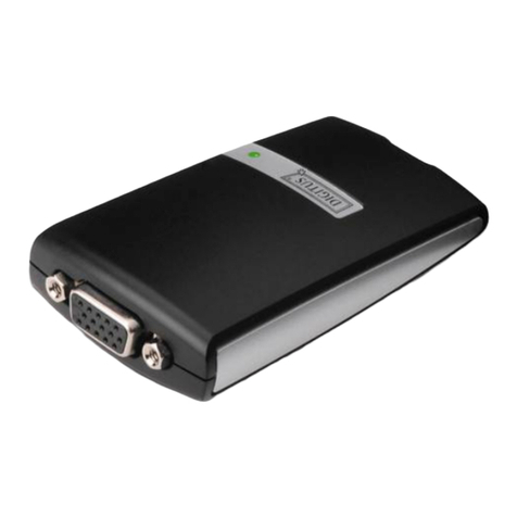
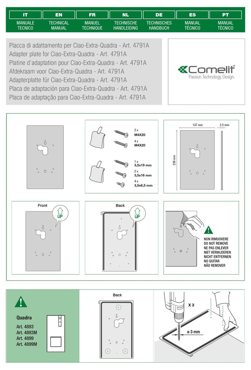
TET SICA14I2P User manual

TET
TOKYO ELETECH CORPORATION
TOKYO ELETECH CORPORATIONTOKYO ELETECH CORPORATION
TOKYO ELETECH CORPORATION
1
1. Product description
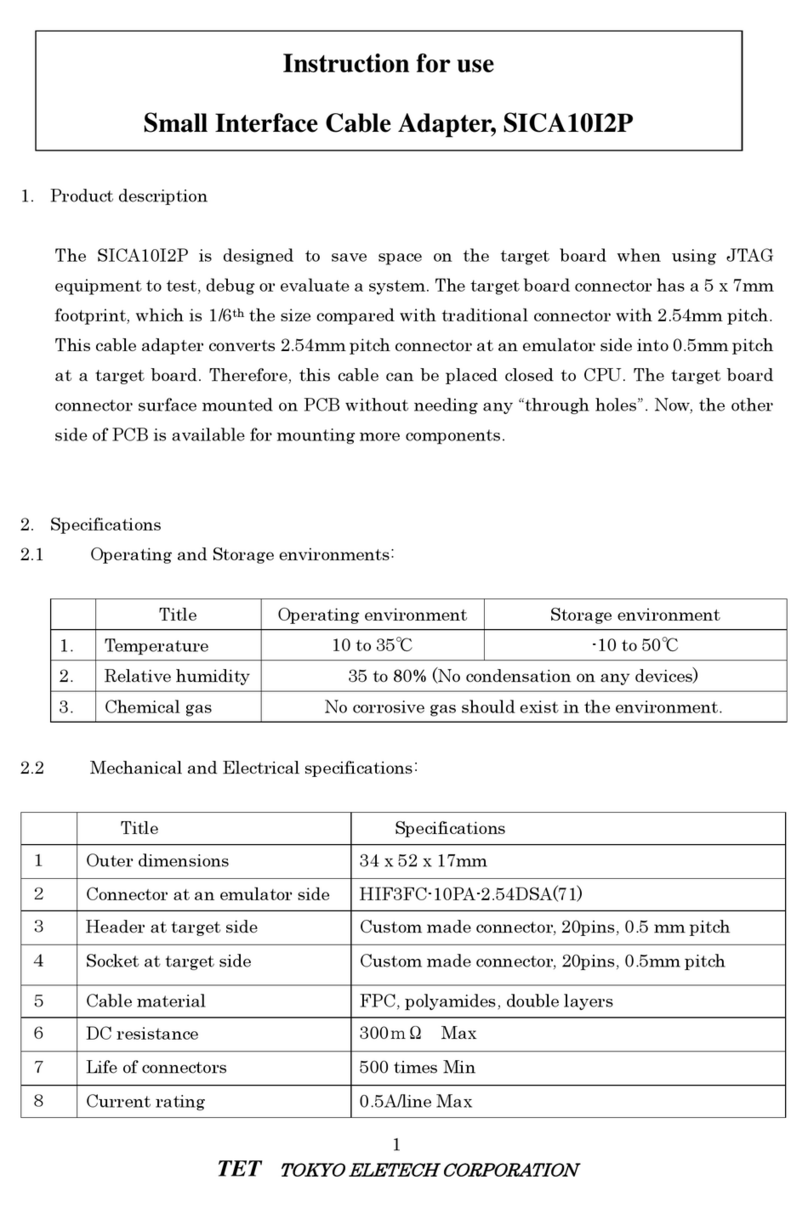
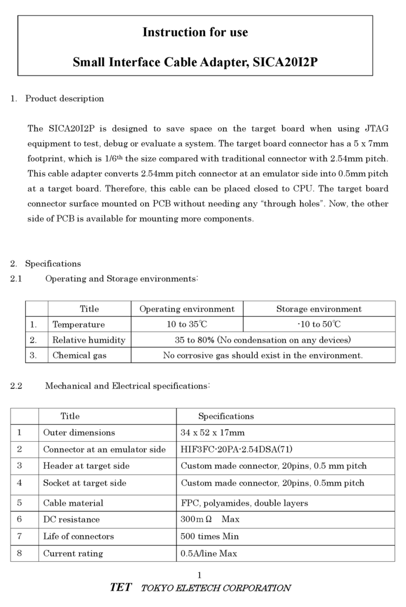
The SICA14I2P is desi ned to save space on the tar et board when usin JTAG
equipment to test, debu or evaluate a system. The tar et board connector has a 5 x 7mm
footprint, which is 1/6th the size compared with traditional connector with 2.54mm pitch.
This cable adapter converts 2.54mm pitch connector at an emulator side into 0.5mm pitch
at a tar et board. Therefore, this cable can be placed closed to CPU. The tar et board
connector surface mounted on PCB without needin any “throu h holes”. Now, the other
side of PCB is available for mountin more components.
2. Specifications
2.1 Operatin and Stora e environments:
Title Operatin environment Stora e environment
1. Temperature 10 to 35℃ -10 to 50℃
2. Relative humidity
35 to 80% (No condensation on any devices)
3. Chemical as No corrosive as should exist in the environment.
2.2 Mechanical and Electrical specifications:
Title Specifications
1 Outer dimensions 34 x 52 x 17mm
2 Connector at an emulator side HIF3FC-14PA-2.54DSA(71)
3 Header at tar et side Custom made connector, 20pins, 0.5 mm pitch
4 Socket at tar et side Custom made connector, 20pins, 0.5mm pitch
5 Cable material FPC, polyamides, double layers
6 DC resistance 300mΩ Max
7 Life of connectors 500 times Min
8 Current ratin 0.5A/line Max
Instruction for use
Small Interface Cable Adapter, SICA14I2P

TET
TOKYO ELETECH CORPORATION
TOKYO ELETECH CORPORATIONTOKYO ELETECH CORPORATION
TOKYO ELETECH CORPORATION
2
2.3 The kit includes:
・ SICA14I2P cable One piece
・ Matin socket at a tar et board(SICA2P20S) One piece
・ Notes for handlin SICA One piece
2.4 Recommend solderin temperature profile on the surface of the matin socket
at tar et side, SICA2P20S.
1. Please visit the followin web site to et the tar et board footprint pattern.
http://www.tetc.co.jp/pdf/sica_zumen/sica2p20s.pdf
2. The thickness and openin of metal mask stencils for SICA2P20S
Thickness : 150μ
Openin of metal mask stencils : 60%
3. Solderin temperatures :
a . Lead free solderin (Sn-3Ag-0.5Cu)
Solder reflow equipment :
Preheatin temperature : 220℃ for 40 seconds max.
Maximum temperature : 260℃
Hand solderin :
Maximum temperature : 380℃ for 3 seconds or less.
b. Tin-lead solderin
Solder reflow equipment :
Preheatin temperature : 200℃ for 30 seconds max.
Reflow temperature : 245℃
Hand solderin :
Maximum temperature : 350℃ for 3 seconds or less.

TET
TOKYO ELETECH CORPORATION
TOKYO ELETECH CORPORATIONTOKYO ELETECH CORPORATION
TOKYO ELETECH CORPORATION
3
3 How to use it:
1. Turn off the power to emulator and the
tar et board! Connect the emulator cable,
the emulator and tar et board as shown in
Fi 3.1.
A polarity key prevents the user to plu the
emulator cable and the SICA to ether in the
wron direction as shown in Fi 3.2. Check
the key’s position before assemblin the
header and the socket.
2. A ain observin the proper key ali nment,
plu the socket on SICA cable tar et end
onto the header on the tar et board as
shown in Fi 3.3.
4 Cable wirin dia ram
Cable wirin dia ram is shown in Fi 4.1 and Fi 4.2. Trian le mark indicates pin#1. The
pin#1 on the SICA connected to pin#1 on the other end. That is, pins are connected to
ま
Target board
SICA
Micro computer
Fi 3.3
Connect
Emulator
SICA
Fi 3.1
図3.1
Connect
Emulator cable
Fi 3.2
SICA
Key
Polarity key
Emulator cable

TET
TOKYO ELETECH CORPORATION
TOKYO ELETECH CORPORATIONTOKYO ELETECH CORPORATION
TOKYO ELETECH CORPORATION
4
strai ht across the cable.
5 Notes for handlin SICA -Small Interface Cable Adapter-
1) SICA is developed for tests, evaluations, and / or development of the electronics system
development in laboratory environment; Therefore SICA does not satisfy any EMI
standards or safety rules.
2) SICA should not be used for the electronics or electrical systems where EMI and
reliability a ainst environments can be a safety factor, such as transportation, medical,
navi ation, nuclear power control system and etc.
3) While developin a new application usin SICA make sure you follow the pin dia ram
exactly as shown in this manual.
4) Do NOT bend flex cable too sharply, because it mi ht break the internal conductive
trace. Insert or extract the cable usin the stiffener.
Specifications, the mechanical construction, all other information mi ht be chan ed without notice.
Specifications, the mechanical construction, all other information mi ht be chan ed without notice.Specifications, the mechanical construction, all other information mi ht be chan ed without notice.
Specifications, the mechanical construction, all other information mi ht be chan ed without notice.
9
4
5
7
8
6
11
12
13
10
14
3
2
1
▼
1
9
4
5
7
8
6
11
12
13
10
14
3
2
1
9
4
5
7
8
6
11
12
13
10
14
3
2
1
14
Fi 4.1
11
13
10
14
1
▼
1
14
1
14
1
14
Fi 4.2
8
4
5
7
6
3
2
9
12
9
4
5
7
8
6
11
12
13
10
3
2
9
4
5
7
8
6
11
12
13
10
3
2
Emulator cable
Emulator cable
Connector at
Emulator side
Connector at
Emulator side
Tar et side header
Tar et side header
TOKYO ELETECH CORPORATION
TOKYO ELETECH CORPORATIONTOKYO ELETECH CORPORATION
TOKYO ELETECH CORPORATION
〒110-0006
3-10 Akihabara Taito-ku,
TOKYO JAPAN
TEL:+81-(0)3-5295-1661
FAX : +81-(0)3-5295-1775
URL : http://www.tetc.co.jp/ 2007.12.10 TET-MANU-SICA14I2P-Rev4
Table of contents
Other TET Adapter manuals
