Tetramodem TGW-100 User manual

TGW-100R / TGW-100
TETRA Gateway
for Packet Data and SDS Applications
V 2.71 –June 2013
Цены и срок поставки уточняйте на сайте www.2test.ru, по телефону: + 7 495 215-57-17 или [email protected]

Funk-Electronic Piciorgros GmbH TGW-100/TGW-100R
V2.71 - Page 2 of 59
1INTRODUCTION......................................................................................................................4
1.1 Overview..............................................................................................................................4
1.2 Safety Precautions................................................................................................................4
1.3 Disclaimer ............................................................................................................................4
1.4 Functions and Features.........................................................................................................5
1.5 Software Options..................................................................................................................6
1.6 Software Versions ................................................................................................................7
2CONNECTIONS AND HARDWARE INSTALLATION......................................................8
2.1 TGW-100: DIN-Rail-Version ..............................................................................................8
2.1.1 Mechanical Details.....................................................................................................11
2.1.2 Dimensions.................................................................................................................11
2.1.3 Mounting....................................................................................................................12
2.1.4 Dismounting...............................................................................................................12
2.1.5 Power Supply Input....................................................................................................13
2.2 TGW-100R: Rack version....................................................................................................8
2.2.1 Mechanical Details.......................................................................................................8
2.2.2 Power supply inputs ...................................................................................................10
2.3 Electrical Connections........................................................................................................14
2.3.1 Serial Interfaces..........................................................................................................14
2.3.2 Secondary Serial Interface (AUX Interface) on TGW-100 DIN-Rail........................15
2.3.3 Ethernet Interface(s)...................................................................................................16
2.4 LED Functions ...................................................................................................................17
2.4.1 DIN-Rail version........................................................................................................17
2.4.2 TGW-100R rack version............................................................................................17
2.4.3 OK LED: Blink Pattern Error Indication....................................................................21
2.5 Reset to factory default (DIN-Rail version).......................................................................22
2.5.1 General Reset of the Device to Factory Default.........................................................22
2.5.2 Resetting the Ethernet Parameter...............................................................................23
2.6 Configuration of the TGW using the embedded web server..............................................24
2.6.1 Navigation using the Menu ........................................................................................25
2.6.2 Requesting Restart of the Device...............................................................................26
3DATA COMMUNICATION OVER TETRA NETWORKS...............................................27
3.1 Data Communication by SDS ............................................................................................29
3.1.1 Selection of the TETRA infrastructure manufacturer................................................30
3.1.2 SDS services for Etelm infrastructures ......................................................................31
3.1.3 SDS services for Cassidian infrasturctures ................................................................32
3.1.4 SDS services for Hytera infrastructures .....................................................................38
3.1.5 Use of the TGW-100 as master gateway....................................................................40
3.1.6 Using the TGW-100 as Slave Device.........................................................................42
3.1.7 Data Compression using the LZ77 algorithm ............................................................43
3.2 Sending and receiving SDS- and Status Messages using the Hash (#) Command
Sequence.............................................................................................................................44
3.3 Packet Data (IP) Communication.......................................................................................46
3.3.1 IP Assignment for the Ethernet Interface ...................................................................47
4PROTOCOLS...........................................................................................................................48

Funk-Electronic Piciorgros GmbH TGW-100/TGW-100R
V2.71 - Page 3 of 59
4.1 Layer one Protocols between TGW-100 and the external device, connected via serial
interface..............................................................................................................................48
4.1.1 Timeout Protocol........................................................................................................48
4.1.2 3964R Protocol...........................................................................................................48
4.2 Serial Protocols (RS-232 or RS-485/RS-422)....................................................................49
4.2.1 Modbus RTU..............................................................................................................50
4.2.2 ROC protocol .............................................................................................................50
4.2.3 DNP3..........................................................................................................................50
4.2.4 IEC 60870-5-101........................................................................................................50
4.2.5 PakBus........................................................................................................................50
4.2.6 BSAP..........................................................................................................................50
4.2.7 User-Protocol .............................................................................................................51
4.2.8 Transparent Data Communication without Protocol Filter (User Defined)...............51
4.2.9 Hart-Protocol..............................................................................................................51
5CONFIGURING THE TGW-100...........................................................................................52
5.1 Configuring the TGW-100 through the Integrated Web Server.........................................52
6MAITENANCE........................................................................................................................53
6.1 TGW-100 Firmware update procedure ..............................................................................53
6.1.1 Preparation and setup.................................................................................................53
6.1.2 Update procedure .......................................................................................................53
6.1.3 Connecting the TGW-100..........................................................................................54
6.1.4 Update using the Windows command line client.......................................................54
6.2 Saving and restoring the configuration...............................................................................56
6.2.1 Save a configuration...................................................................................................56
6.2.2 Restore a configuration ..............................................................................................56
6.3 Using the IPLoader application..........................................................................................56
7SPECIFICATIONS TGW-100................................................................................................57
8TGW-100R FEHLER! TEXTMARKE NICHT DEFINIERT.
8.1 Specifications TGW-100R.................................................................................................57
8.2 Specifications TGW-Rack (19” Rack) ...............................................................................58

Funk-Electronic Piciorgros GmbH TGW-100/TGW-100R
V2.71 - Page 4 of 59
1Introduction
1.1 Overview
This document contains information about installation, settings, and operation of the
TGW-100 TETRA Gateway. This includes practical guidance relating to antenna
selection and installation, operating range, extension modules, software support, etc.
1.2 Safety Precautions
This radio equipment should not be used in life support systems or in safety systems
without our prior written permission.
1.3 Disclaimer
We have carefully checked the contents of this document, and the hardware and
software described in it, for compatibility. We cannot however exclude possibilities of
deviations and cannot guarantee complete conformity of the document with the
equipment it describes. If any corrections or improvements are to be made, they will be
taken into consideration in the next edition of this document.
Important instructions are marked by the expressions "Important", "Note" or “Caution!”.
These should be carefully observed. Explanations regarding these precautions can be
found in the website www.TetraModem.com, in the Login Area pages.

Funk-Electronic Piciorgros GmbH TGW-100/TGW-100R
V2.71 - Page 5 of 59
1.4 Functions and Features
The TGW-100 is a gateway for the connection between automation devices and servers
(SCADA, PLC, PC), mainly used on the master side (i.e. control rooms, SCADA
servers etc.) to make a connection between devices based on serial protocols and a
TETRA network.
The TGW-100 supports nearly all standard and proprietary serial communication
protocols. It has two serial data interfaces (RS-232 or RS-485/422) and an Ethernet
(10/100 Mbits/sec) port. For the data transmission on the TETRA radio network, either
of two modes can be selected: SDS based communication (on supported infrastructures)
or packet data based transmission (working on any infrastructure which allows the
connection of IP based equipment to the TETRA switch).
The main function of the TGW-100 is to connect serial based equipment to the TETRA
network with a direct IP connection to the TETRA switch. This will save the air
interface link on the master side, where normally the data to all outstations will be
routed through. As IP based protocols can directly be connected to the TETRA switch,
serial based protocols must use a gateway device for being connected to the
infrastructure, featuring also a protocol address detection and translation into addresses
which can be handled by the TETRA network (ISSI or IP addresses).
The use of a gateway instead of a radio link on the master side will dramatically
decrease the load on the base station located to the master site and also reduce the
latency by the half of time. It will eliminate the bottleneck of data communication which
is sitting on the master side, where all data needs to pass, if a normal TETRA radio is
used to connect the control room or master SCADA to the TETRA network.
The TGW-100 is delivered as a 19" rack version as "TGW-100R". The rack version
allows the easy mounting in a server cabinet and includes two redundant power
supplies. Up to 3 additional TGW-100 plug-in modules can be placed into the basic
TGW-100R enclosure, giving a total of 4 TGW-100 modules with overall 8 independent
serial ports.
The TGW-100 is also available in a rugged aluminum housing compatible with standard
DIN rail mounting. The wide power input voltage range of 12-24 VDC [+/- 20%] makes
it easy to integrate the unit into monitoring and control systems.

Funk-Electronic Piciorgros GmbH TGW-100/TGW-100R
V2.71 - Page 6 of 59
1.5 Software Options
Basically the TGW-100 can be used to connect serial equipment to any TETRA
infrastructure if the data transmission is done by packet data (IP based) in the TETRA
network.
For a SDS based data transmission, the protocol to send and receive SDS and Status
messages is proprietary for each infrastructure manufacturer as there is no standardized
interface.
Actually the TGW-100 supports SDS based messaging for infrastructures from Etelm.
Other infrastructures may be implemented on project basis.

Funk-Electronic Piciorgros GmbH TGW-100/TGW-100R
V2.71 - Page 7 of 59
1.6 Software Versions
The software (firmware) versions and document editions history is listed below:
Firmware
Version
Document
Version
Comments / Changes
2.20
2.20
Documentation Release
2.60
2.60
TGW-100 supports SDS gateway mode for Cassidian infrastructures
(TCS server needed)
Support of TGW-100R rack mount version
2.70
2.70
TGW-100 supports SDS gateway mode for Hytera infrastructures
(native ACAPI interface support)
Automatic redundancy switchover between two SwMi connections
supported for Hytera and Cassidian SDS interface mode.

Funk-Electronic Piciorgros GmbH TGW-100/TGW-100R
V2.71 - Page 8 of 59
2Connections and Hardware Installation
2.1 TGW-100R: Rack version
2.1.1 Basic information
The TGW-100R (Tetra Gate Way) converts serial communication protocols to TETRA
IP-Data and/or to TETRA SDS Messages. The device has two serial ports for
interfacing to a SCADA Server or NMS Server and two IP (Ethernet) Ports. The TGW-
100R has an embedded Web-Server and can be configured easily using a standard WEB
browser on a Windows PC or MAC device. When beside Packet Switched Data also
SDS messages shall be used, additional individual driver software is needed to interface
the TGW-100R to the different TETRA infrastructure manufacturers.
2.1.2 Mode of operation
Each of the serial ports can be configured independent for a protocol such as Modbus
RTU, DNP3, Sinaut and many others. And for each of these ports a Routing Table as
well as an IP Reference Table will be used to rout the received serial data over the
TETRA infrastructure either as an SDS message or as Packet Data stream to the
outstation(s).
An optional trigger threshold can be used to operate the device in mixed mode and to
send the data depending on its length as an SDS Message or as a Packet Data stream. If
the messages will be send as an SDS, only individual ISSI addressing is used and the
data will be com¬pressed to keep the network load as low as possible.

Funk-Electronic Piciorgros GmbH TGW-100/TGW-100R
V2.71 - Page 9 of 59
2.1.3 Mechanical Details
The TGW-100R is enclosed in a black 19" rack mount enclosure with 3 height units.
The main rack has 2 independent power supplies with separated IEC power connectors
on the back. Cables with a European power plug are delivered with the rack.
One TGW-100R rack can support up to 4 TGW-100R plug-in modules, each with two
serial ports for connection to the SCADA equipment.
2.1.4 Interfaces
Both serial interfaces ("COM" and "AUX") use a standard 9-pin D-sub connector. Also
available on the front panel are two Ethernet connectors which are connected by an
internal Ethernet switch. This allows the chaining of the up to 4 plug-in TGW-100R-
units in a rack to a single uplink cable or the easy connection of a PC for configuration.
In total, eight serial interfaces can be realized in one 19" enclosure.
LED lamps on the front panel provide information about the operating condition of the
unit, the Rx and Tx status of all interfaces and the link status to the TETRA
infrastructure in case that the gateway is used for SDS based data transfer.

Funk-Electronic Piciorgros GmbH TGW-100/TGW-100R
V2.71 - Page 10 of 59
2.1.5 Power supply inputs
The power inputs of the TGW-100R enclosure are located at the back. There is one IEC
power input plug for each power supply, equipped with an on-off switch and two fuses
(2A medium speed).
The IEC plugs are secured against unwanted removal by a lock. To remove the plug, the
red lever on the plug must be pulled while the plug is drawn out.
Two cables with a European plug are included in the delivery, for other countries you
may ask for cables fitting the needs. Also standard cables with IEC plug may be used,
but please aware that you'll lose the removal lock with a standard plug.
IEC plug with removal lock
As each power supply has its own power input, a connection to redundant power trunks
is possible. Even if one power supply fails, the TGW-100R with all plug-in modules
will remain fully operational.
Beside the normal operational LED on each power supply which shows the availability
of main source, each TGW-100R plug-in module also shows the status of both power
supplies (named with "Pwr L" for the left module and "Pwr R" for the right module).
The power supply modules can be hot-swapped, an exchange is possible during
operation.

Funk-Electronic Piciorgros GmbH TGW-100/TGW-100R
V2.71 - Page 11 of 59
2.2 TGW-100: DIN-Rail-Version
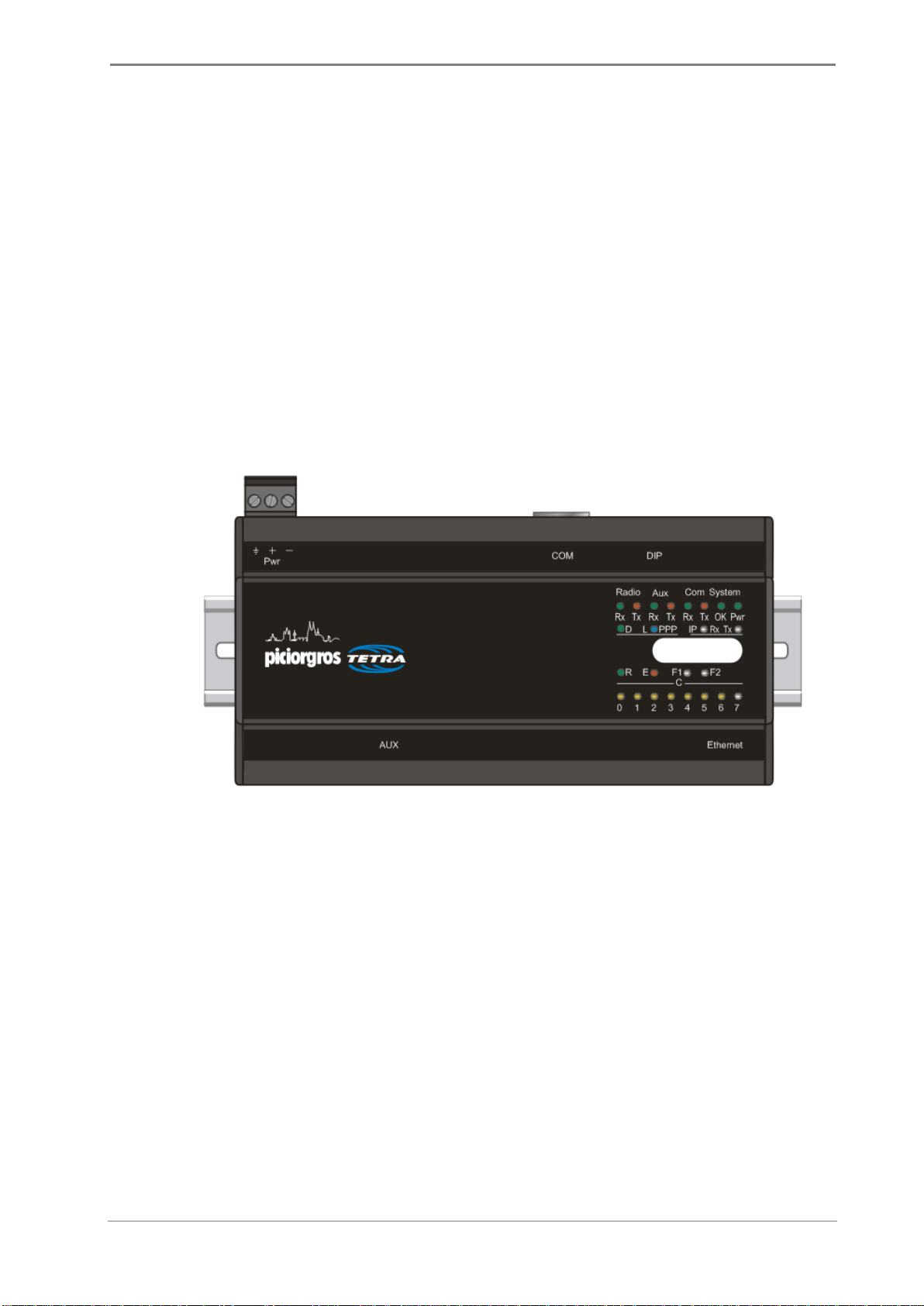
2.2.1 Mechanical Details
The dimensions of the TGW-100 housing conform to DIN 43880, and therefore it can
be mounted on a standard 35mm DIN rail [DIN EN 50022]. Two serial interfaces are
provided for connecting the TGW-100 to a PC/PLC or other local terminal equipment.
The main serial interface ("COM") uses a standard 9-pin D-sub connector, while the
secondary serial interface ("AUX") uses a standard RJ-11 socket. On the lower side of
the housing an RJ-45 connector for the Ethernet port allows the TGW-100 to be hard-
wire networked with the TETRA infrastructure.
On the left upper side of the unit is located the plug-in terminal connector for the power
supply (12-24 VDC +/-20%) and a BNC socket for the antenna.
A 10-pole DIP-switch allows quick changes to the unit's settings: e.g., changeover to
Programming Mode.
LED lamps on the front panel provide information about the operating condition of the
unit: e.g., received TETRA RF signal strength, error conditions, etc.
2.2.2 Dimensions
The dimensions of the TGW-100 are as follows:
162mm (9T) wide x 80mm high x 62mm deep
All dimensions exclude connectors.
Funk-Electronic Piciorgros GmbH TGW-100/TGW-100R
V2.71 - Page 12 of 59
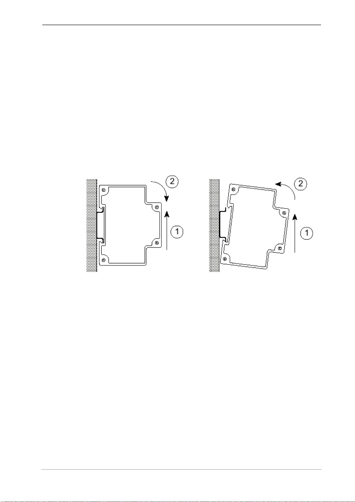
2.2.3 Mounting
The DIN rail mounting clip is at the bottom of the Module. First the lower lip (spring-
loaded) of the clip is engaged with the lower flange of the DIN rail, with the Module
tilted downward slightly. The Module is then pushed upward (1) and rotated backward
(2) until the upper lip of the clip snaps onto the upper flange of the DIN rail.
2.2.4 Dismounting
To dismount the Module, force it upwards (1), and then rotate its upper end outward (2)
until the upper lip of the Module's clip disengages from the upper flange of the rail.
Then move the Module down slightly to disengage its lower lip from the rail flange.
Mounting Dismounting
Funk-Electronic Piciorgros GmbH TGW-100/TGW-100R
V2.71 - Page 13 of 59
2.2.5 Power Supply Input
The required supply voltage (12-24 VDC +/-20%) is connected through 3-way screw
terminal connector located on the upper side of the enclosure.
The terminals are assigned as follows (viewed from the front of the module, facing the
front panel):
Outer (left): Enclosure Ground (electrical earth)
Middle: + 12 Volt to + 24 Volt (+/- 20%)
Inner (right): GND, 0 Volt from Power Supply

Funk-Electronic Piciorgros GmbH TGW-100/TGW-100R
V2.71 - Page 14 of 59
2.3 Electrical Connections
2.3.1 Serial Interfaces
The TGW-100 has two serial data interfaces. The primary interface (COM) can be either
RS-232 or user-selectable RS-422/485. The AUX interface can be RS-232 or RS-485
(only).
The following parameters are user adjustable: baud rate in the range 300 - 57600 bps,
data word length 7 or 8 bits, odd / even / no parity, and 1 or 2 stop bits. The factory
setting is 9600 bps, 8 data bits, no parity, 1 stop bit.
If a frame error is detected, or if the parity bit does not conform to the setting, the
received data block is rejected.
Both serial interfaces are supplied as RS-232, unless ordered otherwise. The primary
interface is optionally available as a user-selectable RS-485 / RS-422 port, while the
AUX interface is optionally available as an RS-485 port. Note that the RS-485 / RS-422
interface does not have the CTS/RTS lines.
Pin No.
Pin Assignment: DB9, RS-232
2
TxD Send data TGW-100 peripheral
3
RxD Receive data TGW-110 peripheral
4
DTR Shorted to Pin 6
5
GND
6
DSR Shorted to Pin 4
7
RTS Handshake TGW-100 peripheral
8
CTS Handshake TGW-100 peripheral
Pin No.
Pin Assignment: DB9, RS-422
2
A Receiver + (input)
3
Z Transmitter –(output)
5
GND
7
B Receiver –(input)
8
Y Transmitter + (output)
Pin No.
Pin Assignment: DB9, RS-485
3
B Transceiver –
5
GND
8
A Transceiver +
For the connection of the COM interface to a PC or PLC, use a standard 1:1 connector-
terminated cable (9-pin D-sub male to 9-pin D-sub female).
Funk-Electronic Piciorgros GmbH TGW-100/TGW-100R
V2.71 - Page 15 of 59
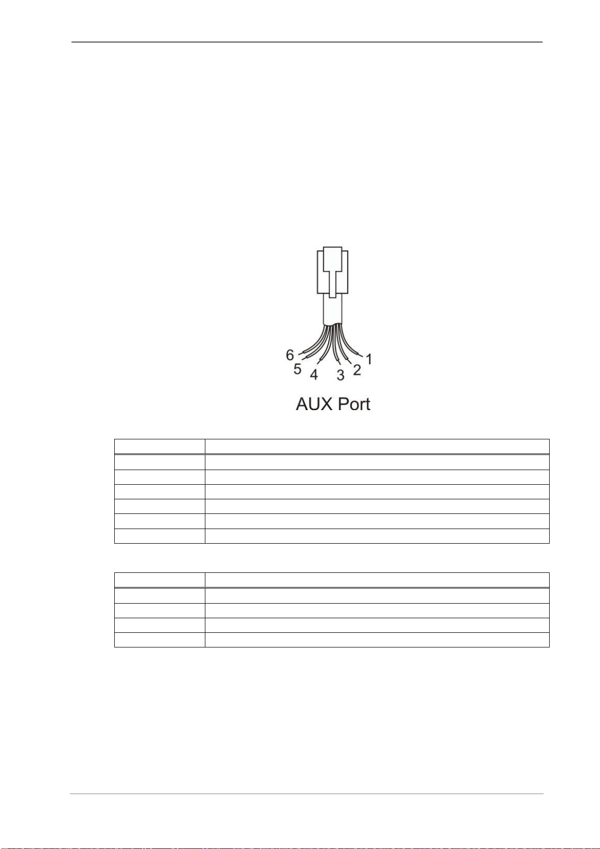
2.3.2 Secondary Serial Interface (AUX Interface) on TGW-100 DIN-Rail
On the TGW-100 DIN-Rail-version, the AUX interface socket is located on the lower
side of the unit. This interface allows the implementation of special applications, e.g.,
switching of the data-flow through this interface by a command, or feeding data from a
predefined ISSI to this port rather that to COM.
This secondary interface is provided through a 6-pin RJ-12 connector and equipped
default with an RS-232 interface. The unit can be ordered optional with an RS-485
interface (RS-422 is not possible on the AUX port).
Pin No.
Pin Assignment: Auxiliary Interface, RS-232
1
GPS Supply voltage
2
RTS Handshake TGW-100 peripheral
3
RxD Receive data TGW-100 peripheral
4
TxD Send data TGW-100 peripheral
5
CTS Handshake TGW-100 peripheral
6
GND
Pin No.
Pin Assignment: Auxiliary Interface, RS-485
1
GND
3
B Transceiver –
4
A Transceiver +
6
GND
On the TGW-100R rack version, also the AUX port is realized with a standard
DB9 connector!

Funk-Electronic Piciorgros GmbH TGW-100/TGW-100R
V2.71 - Page 16 of 59
2.3.3 Ethernet Interface(s)
The Ethernet interface is provided via an RJ-45 socket on the underside the unit. This is
a standard 10/100 Mbit/s interface. Two LEDs indicate the operating condition of this
interface:
Green LED: Lights up when an Ethernet network is connected (LINK)
Yellow LED: Blinks when data transfer is taking place (DATA)
Network parameters such as IP address, netmask, and gateway address can be assigned
as a static address.
A TGW-100R plug-in-module is equipped with two Ethernet plugs. Both Ethernet plugs
are internally connected by an Ethernet switch. Any interface can be used for the
Ethernet connection, but due to the availability of the second port, the IP network can be
chained to the next TGW-100R module in a very easy way.

Funk-Electronic Piciorgros GmbH TGW-100/TGW-100R
V2.71 - Page 17 of 59
2.4 LED Functions
Groups of LED lamps on the front panel of the TGW-100 indicate the operating
condition of the modem, the link to the TETRA infrastructure, and error conditions if
any. Specific LED functions are described below.
2.4.1 TGW-100R rack version

Funk-Electronic Piciorgros GmbH TGW-100/TGW-100R
V2.71 - Page 18 of 59
LED
Function
System Pwr
Power supply input
System OK
Indicates the "Ready" status of the modem (continuously lit). Also
indicates error conditions (coded blink sequences).
COM Tx
Lights up while the TGW-100 sends data via the COM interface
COM Rx
Lights up while the TGW-100 receives data via the COM interface
Aux Tx
Lights up while the TGW-100 sends data via the AUX interface
Aux Tx
Lights up while the TGW-100 receives data via the AUX interface
IP Tx
Lights up while the TGW-100 sends data to the infrastructure for
packet data transmission
IP Rx
Lights up while the TGW-100 receives data from the infrastructure
from packet data transmission
SDS Tx
Lights up while SDS or Status data is being sent to the
infrastructure
SDS Rx
Lights up while SDS or Status data is being received from the
infrastructure
Link (blue)
Off: No link to TETRA SwMi or TGW-100 is operating as packet
data gateway
Flashing: Trying to connect to the TETRA SwMi in SDS mode
Permanent on: Shows active link to the TETRA infrastructure in
SDS gateway mode

Funk-Electronic Piciorgros GmbH TGW-100/TGW-100R
V2.71 - Page 19 of 59
2.4.2 DIN-Rail version

Funk-Electronic Piciorgros GmbH TGW-100/TGW-100R
V2.71 - Page 20 of 59
LED
Function
System Pwr
Power supply input
System OK
Indicates the "Ready" status of the modem (continuously lit). Also
indicates error conditions (coded blink sequences).
COM Tx
Lights up while the TGW-100 sends data via the COM interface
COM Rx
Lights up while the TGW-100 receives data via the COM interface
Aux Tx
Lights up while the TGW-100 sends data via the AUX interface
Aux Tx
Lights up while the TGW-100 receives data via the AUX interface
IP Tx
Lights up while the TGW-100 sends data via the Ethernet interface
IP Rx
Lights up while the TGW-100 receives data via the Ethernet
interface
Radio Tx
Lights up while SDS or Status data is being sent to the
infrastructure
Radio Rx
Lights up while SDS or Status data is being received from the
infrastructure
RF
These Led bar indicates the correct registration to the TETRA
infrastructure if the TGW-100 is in SDS gateway mode. During
startup, a yellow LED point runs from the right side to the left
side. As soon as the TGW-100 is registered to the infrastructure,
all 8 LED will light up (this gives the same picture like the TGW-
100 when it's attached to the network with full field strength).
In case of a connection problem, LED 4 flashes continuously. This
indicates that the IP connection to the TETRA infrastructure is lost
or the infrastructure is not responding properly to the
communications from the TGW-100.
PPP Data
not used
PPP Link (blue)
Shows active link to the TETRA infrastructure in SDS gateway
mode
R,E,F1,F2
not used
This manual suits for next models
1
Table of contents
Popular Gateway manuals by other brands

Panasonic
Panasonic KX-TDA0484 Getting started

Sophos
Sophos Astaro 625 operating instructions

Proxim
Proxim Skyline user guide

Mitsubishi
Mitsubishi GOT2000Series Connection manual

ZyXEL Communications
ZyXEL Communications UAG Series quick start guide

ZyXEL Communications
ZyXEL Communications P-660HWP-D1 user guide


Spirent
Spirent DX3-QSFP-DD-8 installation instructions

Glomex
Glomex ZigBoat ZB100 owner's manual

ZyXEL Communications
ZyXEL Communications p-2302r series Specifications

AudioCodes
AudioCodes M500L Hardware installation manual

RTA
RTA 460TCP-N2E Product user guide

Ursalink
Ursalink urbana GI01 quick start guide