Texecom Premier Elite 32XPH-W User manual
Installation Manual
Premier Elite 32XPH-W
INS732

Premier Elite 32XPH-W Installation Instructions
2 INS732
1. Contents
1. Contents...............................................2
2. Premier Elite 32XPH-W ........................3
System Requirements.................................... 3
System Design Considerations ..................... 4
Multiple Expander Systems.............................. 4
Learning Devices ............................................. 4
Placing Devices ............................................... 4
3. Quick Start Guide ................................ 4
4. System Overview .................................5
Mounting the Expander.................................. 6
Wiring ............................................................. 6
Selecting an Address..................................... 6
Ricochet Expander Addressing..................... 7
Introduction ..................................................... 7
Example: Totally wireless system(s)................. 7
5. Programming .......................................7
Premier Elite™ V2.10> 12/24/48/88/168
Ricochet Learn Menu..................................... 7
Auto Zone Type & Area.................................. 8
Deleting Devices ............................................ 9
Summary of Keys used.................................. 9
Premier EliteV2.00 - V2.09 24/48/88/168 & 640
+ Ricochet V2.xx............................................ 9
Introduction ..................................................... 9
Deleting Devices............................................ 10
Device Modes of Operation............................ 10
Zone Types & Attributes................................. 11
Standalone Mode......................................... 12
Standalone Operation.................................. 12
This table shows two example systems...... 13
6. Ricochet Diagnostics ......................... 13
Premier Elite V2.XX ...................................... 13
Devices.......................................................... 13
Interpreting Keypad Displays ......................... 13
Ricochet Diagnostics Menu ........................... 15
Premier Elite V3.XX ...................................... 16
Low signal security ........................................ 16
7. Modes of Operation ........................... 16
Commission Mode....................................... 16
Expander....................................................... 16
Device Commission Mode ............................. 16
8. System Attributes .............................. 17
Polling .......................................................... 17
System Devices............................................ 17
Auto Mode..................................................... 17
Always Awake................................................ 17
Device Specific .............................................. 17
Hybrid Mode (V2.xx) ...................................... 17
Premier Elite 32XPH-W Power Loss ............ 18
9. Specifications .................................... 18
Electrical........................................................ 18
Physical..........................................................18
Standards & Directives ...................................18
Standards ......................................................18
FCC ID: MYJLAIA5000....................................18
FCC warning statement:.................................18
Warranty.........................................................19

Premier Elite 32XPH-W Installation Instructions
INS732 3
2. Premier Elite 32XPH-W
Texecom has developed a new method of wireless security signalling based on the concept of mesh
networking. Mesh-networking is the process whereby every single wireless device is capable of receiving and
retransmitting any signal from any other wireless device on the network. The size, scalability and range of the
entire system are extended as wireless signalling is no longer limited by point-to point communications. The
range of a Ricochet®enabled wireless system is greater than previous systems, with multiple devices capable
of relaying messages to and from even the most remote locations in a building. Each Ricochet enabled
device provides signalling routes to and from control panels. If the wireless communication between devices
weakens, the Ricochet network ‘self-heals’ and automatically re-routes communications via alternate Ricochet
enabled devices. The reliability of the wireless system increases as more Ricochet devices are installed.
SignalSecurity™ further enhances network reliability with each device already aware of the number of
communication paths available to it.
Firmware versions prior to those listed are NOT compatible.
Control Panel
Premier Elite 32XPH-W
Legacy
Ricochet
Ricochet V2.xx
** V2.10 > Premier Elite
12/24/48/88/168 & 640*
See Section 3
N/A
V2.10>
V2.10>
Multiple Expander Support
It is now possible to add multiple expanders to the system allowing for greater flexibility in system design, and
also taking wireless capability to new levels.
Control Panel Capacity
The table below details the maximum number of expanders and devices that may be used on the different
control panels.
Panel
32XPH-W
Expanders
Devices
Premier Elite 12-W & Live™
N/A
N/A
Premier Elite 24™
1
16
Premier Elite 48™
1
32
Premier Elite 48-W™
N/A
32
Premier Elite 88™
2
64
Premier Elite 168™
4
128
Premier Elite 640™
16
512
Premier Elite 32XPH-W take 4 address slots on the network.
System Requirements
To enable all of the advanced functionality and diagnostics capability Ricochet the following are minimum
requirements:-
Wintex™ Version 6 Build 16 or later
Ricochet Monitor™ 0.2.15.00 or later
Premier Elite™ Series V2.xx or later
Premier Elite™ 32XPH-W Expanders V2.xx or later
Expander firmware version can be found on the round green sticker located on the RH side of the PCB.

Premier Elite 32XPH-W Installation Instructions
4 INS732
System Design Considerations
To ensure correct setup and operation of the Wireless Network it is important that the following procedures
are used when learning and placing devices.
Multiple Expander Systems
When using multiple expanders great care should be taken when designing the system. Each expander
should be treated as its own wireless network; it is not possible for devices to hop from one wireless network
to the other, it is also not possible for expanders to pass wireless signals from devices not assigned to them
and nor can the expanders talk to each other.
Learning Devices
All devices should be learnt before they are placed in their final location. The expander should be in
commission mode, please see page 16.This will ensure that they are registered on the receiver or control
panel, and that Mesh Networks and routing are established correctly. Please refer to the relevant section in
this document to Learn Devices to the system.
Devices should be at least 1Mtr away but ideally 10m from the receiver when being learned.
Placing Devices
Once all of the devices have been learnt, they will need placing in their desired location, this should be done
by installing devices closest to the expander first and then working outwards so that the last devices installed
are those furthest away from the expander.
Make sure to install devices with the expander in Commission mode. See page 16.
Devices also have a commission mode which will indicate a secure and valid path of communication to the
receiver. See page 16.
You should wait at least 20 minutes after installing the last device to make sure routing has been correctly
established between all system devices.
For maximum reliability and system integrity avoid long and thin set-ups. Do not mount devices on or near metal.
Keep devices away from mains electricity supplies.
Devices are capable of hopping through up to two other devices, or a maximum of three hops.
3. Quick Start Guide
1. Connect Receiver to Control Panel Network & Leave Tamper Circuit Open. See Page 6
2. Ensure all Option Switches are off. See Page 5
3. Learn Devices to Control Panel. See Page 7 Onwards
4. set attributes. See Page 7 Onwards
5. Change Device Attributes according to application. See page 10
6. Place Devices in desired location, use LED to indicate Signal Security. See Page 4 & 16
7. Wait 20 Minutes for Mesh Network to establish
8. Walk Test System.
Premier Elite 32XPH-W Installation Instructions
INS732 5
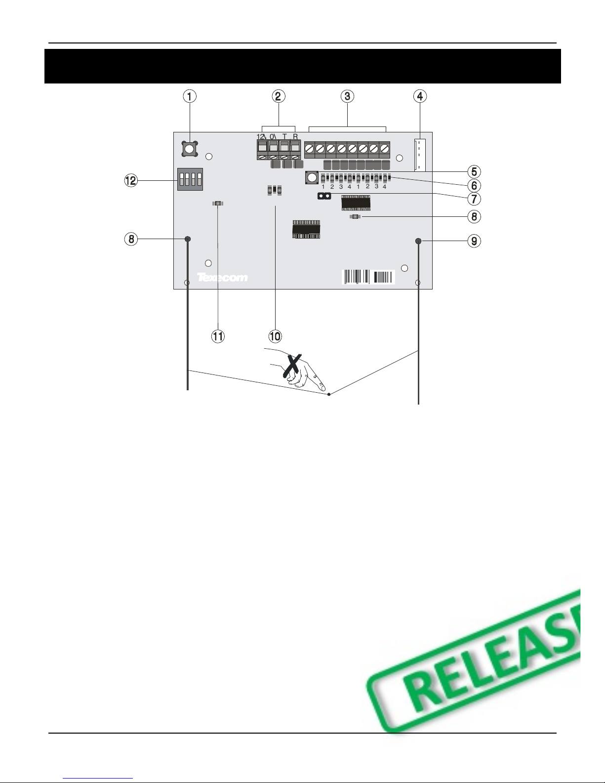
4. System Overview
1 2 3 4 5 6 7 8
1
ON
2 4
3
TX RX
NETWORK
ADDRESS
4 5 4 2 5 6 3 9 12581
TAMPER
DISABLE
1: Function Switch
Used to Learn devices in Standalone mode, and
to clear latched outputs.
2: Network Connection
The + and –terminals provide power whilst the T
and R terminals are transmit and receive data.
3: Outputs 1-8
Eight transistor outputs which can indicate the
status of nodes 1-16. See page 12 for details.
4: Comm. Port Connection
Serial communications port for connecting the
32XPH-W to a PC via PC Com/USB Com or Com
IP/WiFi for use with Ricochet Monitor Software.
5: Lid Tamper
When open puts the system into commission
mode and digitally attenuates the receiver signal
by 15Db.
6: Programming LED’s
Allows programming of devices directly to the
receiver, in conjunction with the learn switch
(Standalone mode only).
7: Tamper Disable
Disables the lid and rear tamper
8: RF LED
Flashes when transmitting or receiving RF data
9: Antenna
RF Antenna
10: Network LED’s
Green LED = Data received by the expander
from the panel Red LED = Data transmitted by
the expander to the panel. (The flash rate
depends on the mode and RF activity)
11: Heartbeat LED
Flashes steadily to indicate that the receiver is
functioning correctly. If the light is ON or OFF all
the time, then there could be a hardware
problem.
12: Address Switch/Option Switch (Standalone
Mode Only)
Used to assign the address of the receiver on the
network when connected to a control panel.
Options switches when used in Standalone
Mode.

Premier Elite 32XPH-W Installation Instructions
6 INS732
Mounting the Expander
Remove each screw cap by inserting a flat bladed screwdriver into the slot and turning anti-clockwise,
excessive force is NOT required. Remove both of the cover screws and put them in a safe place along with
the screw caps. Gently pull the cover away from the base applying slight pressure to the sides at the top of
the expander if required. The front cover should now be off. Mount the expander using at least two
appropriate countersunk screws (no larger than No. 8). A keyhole slot has been provided to assist mounting
and aid levelling. If required a screw should be placed into the knockout on the rear of the expander to enable
the rear/wall tamper.
Do not mount near metal or mains supplies. When using with metal control panels a minimum of 50cm gap is
required. Do not mount near aerials of any description, or other wireless equipment.
Wiring
It is strongly recommended that the system is completely powered down (mains and battery) before wiring
the expander. Connect the expander to the control panel using 4-core cable as follows:
Expander
Control Panel
Description
+
+
+12V Supply
-
-
0V Supply
T
T
Transmit Data
R
R
Receive Data
The networks are made up of four terminals incorporating power and data. To ensure correct operation, all
four terminals on the device must be connected to the corresponding terminals on the control panel or
previous device. Expanders can be connected using 4-core cable. However, it is recommended that 6 or 8-
core cable is used as the spare cores can be used to ‘Double Up’ on the power connections if needed.
Standard 7/0.2 alarm cable can be used for most installations. However, under certain conditions it may be
necessary to use screened cable.
Selecting an Address
Each expander must be assigned a different address using the DIL switches located on the PCB. The table
below shows the expander addressing:
Address
DIL 1
DIL 2
DIL 3
DIL 4
1
On or Off
Off
Off
Off
2
4
3
1
2
Off
On
Off
Off
2
4
3
1
3
Off
Off
On
Off
2
4
3
1
4
Off
Off
Off
On
2
4
3
1
5
On
Off
Off
On
2
4
3
1
6
Off
On
Off
On
2
4
3
1
7
Off
Off
On
On
2
4
3
1
8
On
Off
On
On
2
4
3
1
Never set two expanders on the same network to the same address. Expanders are factory set to address 1.

Premier Elite 32XPH-W Installation Instructions
INS732 7
Ricochet Expander Addressing
Introduction
The address range and switch position will depend on which combination of expanders are being used. Each
32XPH-W takes up 4 address slots on the control panel network, however the network slots are virtual until
devices are assigned to available zones. It is possible that if a 32XPH-W is being used at Address 1, but only
16 devices have been used, Address 3 & 4 are available for hardwired 8XP's.
Please see some examples of mixing different types of Expanders on various Elite panels and the addressing
requirements.
Example: Totally wireless system(s)
Panel
32XPH-W
Network 1
Network 2
Network 3
Network 4
Network 5
Network 6
Network 7
Network 8
Expanders
(Max)
2
2
2
2
2
2
2
2
Premier
Elite 88™
Exp
1
Exp
2
N/A
N/A
N/A
N/A
N/A
N/A
N/A
N/A
N/A
N/A
N/A
N/A
N/A
N/A
Expander
Address
1
5
N/A
N/A
N/A
N/A
N/A
N/A
N/A
N/A
N/A
N/A
N/A
N/A
N/A
N/A
Premier
Elite 168™
Exp
1
Exp
2
Exp
1
Exp
2
N/A
N/A
N/A
N/A
N/A
N/A
N/A
N/A
N/A
N/A
N/A
N/A
Expander
Address
1
5
1
5
N/A
N/A
N/A
N/A
N/A
N/A
N/A
N/A
N/A
N/A
N/A
N/A
Premier
Elite 640™
Exp
1
Exp
2
Exp
1
Exp
2
Exp
1
Exp
2
Exp
1
Exp
2
Exp
1
Exp
2
Exp
1
Exp
2
Exp
1
Exp
2
Exp
1
Exp
2
Expander
Address
1
5
1
5
1
5
1
5
1
5
1
5
1
5
1
5
5. Programming
Premier Elite™ V2.10> 12/24/48/88/168 Ricochet Learn Menu
V2.10> contains a dedicated Ricochet learn menu accessible via the /key when in Engineer menu.
Learn Devices from first power up
Follow the instructions given in INS176-8 or later for the first power up of the system.
When the "Confirm Devices" menu appears check and make sure all installed Keypads and Expanders are
showing; press /and /again to confirm.
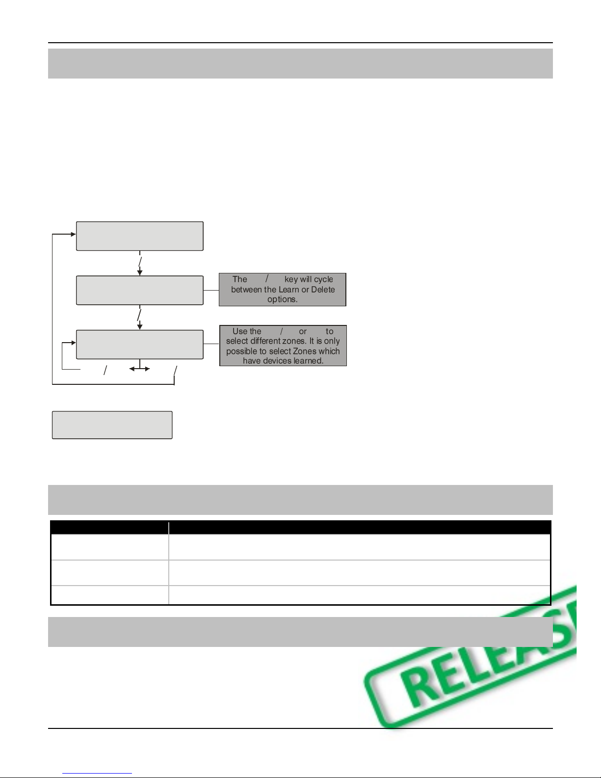
Providing the system has a Ricochet®enabled expander installed, the following will appear. The flow
diagram shows the procedure to learn devices:-

Premier Elite 32XPH-W Installation Instructions
8 INS732
YES to Select:-
Learn Ricochet
Learn Device?
Zone ??? N?,E??
Power up Device!
N?,E?,D?? - 20s
Learn Device to
Zone ??? N?,E??
nnU
NN
Access the Learn Menu using the Omit “Hot” key
From any top level engineering menu pressing the /key will take you to the Ricochet learn menu
above.
Menu
/
Ricochet Learn Menu
YES to Select:-
????????????????
/
YES to Select:-
Learn Ricochet
IMPORTANT
In all cases when entering the Learn menu the next available free Zone will be chosen to learn a device too. It
will not be possible to learn a device to a Zone that already has a device learned too it. The number of
expander’s on the system will dictate which next “free” zone is chosen to learn too.
When all device slots have been used the following screen will be shown
All Devices
Learnt!
Pressing the N/Nkey will return you to the Ricochet®learn menu; pressing the /key will enter
the Delete devices menu.
Auto Zone Type & Area
When learning devices, if no editing has taken place of the control panel on-board hardwired zones, these will
be switched to Not Used after the first Ricochet®device is learned to the system; the following defaults will
be used for Ricochet®devices learned to the system.
Zone
Type
Area
001-008
Not Used
N/A
009
Entry/Exit 1
A
010
Guard Access
A
011 & above
Guard
A
IMPORTANT
If any editing of any of the on board control panel zones is carried out BEFORE any Ricochet devices are
learned too the system, the control panel zones will remain at factory defaults.
Premier Elite 32XPH-W Installation Instructions
INS732 9
Deleting Devices
Delete Devices
To delete devices from the system, access the Ricochet Learn menu. Any of the methods previously detailed
may be used.
The /key is used to access the Delete option.
Follow the flow diagram to delete devices from the system.
To delete all devices, go to Engineer Utilities/Ricochet Diagnostics. Scroll to the first wireless zone for
the expander being defaulted and press /followed by /. All zones will be deleted.
YES to Select:-
Learn Ricochet
Learn Device
Zone ??? N?,E?
Delete Device?
Zone ??? N?,E?
nnU
NN
If all devices are deleted from the system the following will be shown
All Devices
Deleted!
Pressing the N/Nkey will return you to the Ricochet learn menu; pressing the /key will enter
the Learn devices menu.
Summary of Keys used
Key
Function
/
Use this key to access the Ricochet Learn menu from any top level engineering
menu.
/
Use this key when in Ricochet Learn menu to delete devices, or cycle between
learn and delete functions
N/N
Use this key to exit the Learn Menu.
Premier EliteV2.00 - V2.09 24/48/88/168 & 640 + Ricochet V2.xx
Introduction
V2.xx firmware added the option to learn Ricochet devices through the Zone Setup Menu, the "Configure
Radio" menu in Engineer's Utilities is now redundant and should only be used for Legacy systems.

Premier Elite 32XPH-W Installation Instructions
10 INS732
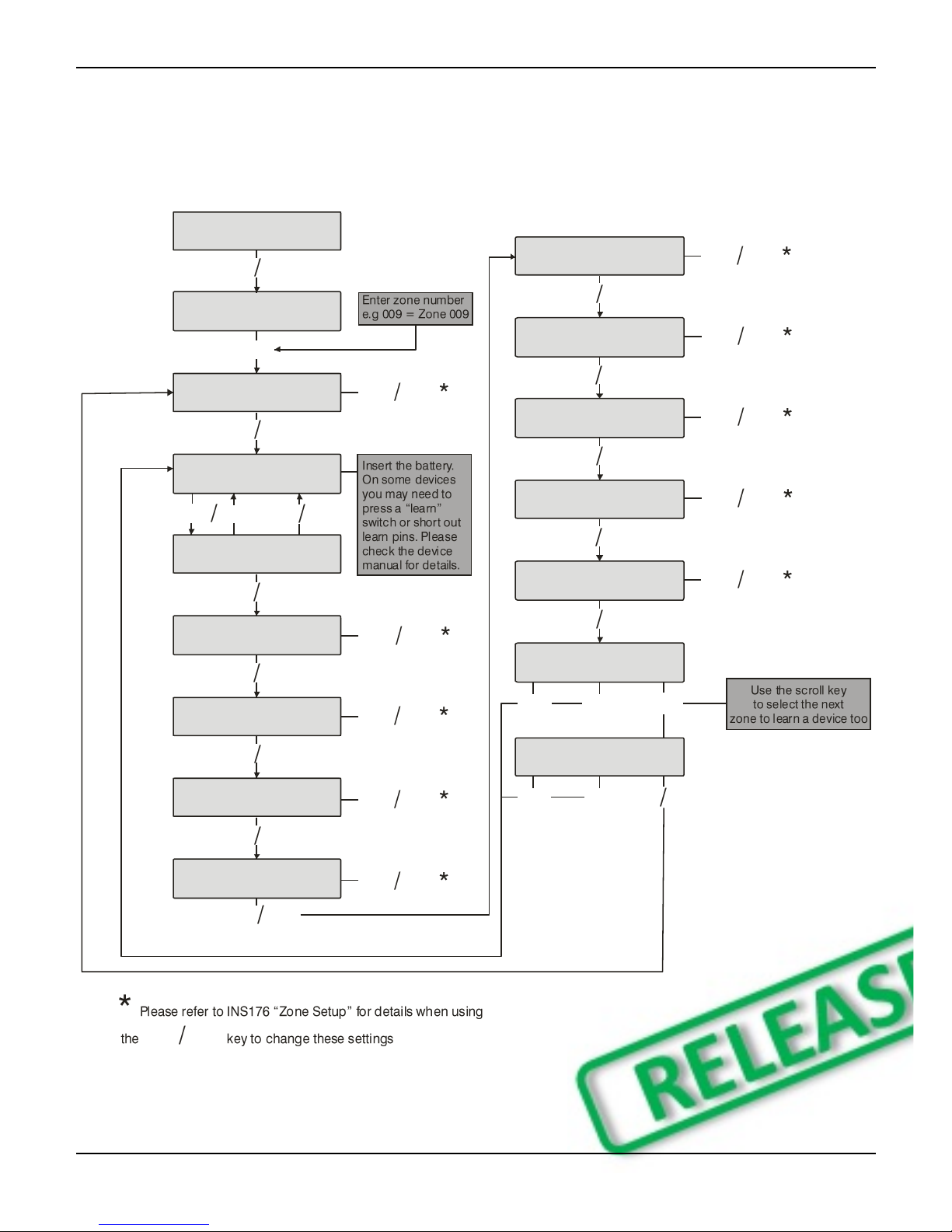
Learning Devices
To learn a device to a Zone select the Zone from the Zone Setup Menu, Zones that are capable of having a
Ricochet device learnt to them will be displayed as follows:-
Zone 00 P0,0
Not sed
Fig 1
Fig 1indicates the pre-assigned zone number, the expander being used and the device slot on the expander.
Once a device has been learnt the display will be as Fig 2:-
Zone 00 Learn:
PR P-0,0
Fig 2
If you are unsure if a zone already has a device learned to it, you can go to the menu as in Fig 1, press
/and then n/nif a device is already learnt the display will look like Fig 2, if not then it will
look like Fig 3
Zone 00 Learn:
ree P-0,0
Fig 3
Please see the diagram on the next page to learn devices.
Deleting Devices
To delete devices from the expander is the same as learning them; choose the zone you wish to delete, and
follow the procedure to learn the device, when the screen shows “Learning” press /.
To default the expander completely, disconnect the T and R lines, put option switch 1 & 2 to ON and hold the
white function button until the expander programming LED's all illuminate and turn off.
Device Modes of Operation
Always Awake
This mode should only be used on devices which are required to signal at all times and is the default setting
for perimeter detection devices such as Contacts and Shock sensors & PA Buttons.
Auto Mode
When in Auto Mode, devices poll at 15 minute intervals. Following activation, devices will not transmit the
same activation again for a period of 3 minutes. This mode of operation is the default mode for all single
technology motion detectors.
Hybrid Mode
Hybrid mode is used to control the reporting functions for devices. When in this mode devices are awake only
when the system is set. Devices are woken up by the control panel at the point of arming. The system will
display "Preparing to Arm". When the system is disarmed the devices will be put back to sleep. This mode of
operation is the default mode for all Dual Technology motion detectors.
On very large systems (100 devices +) a small delay may be experienced when arming the system, this is normal
as the expanders on the system wake up the relevant devices.
Premier Elite DT-W should ALWAYS be used in Hybrid mode, failure to do this will have an adverse affect on
battery life.
Device Specific Mode
Device Specific mode is used to control the reporting functions for devices. Devices that use this mode of
operation have specific operating parameters and should not be altered. This mode of operation is the default
mode for all Fire detectors (Smoke, Heat and any other variant), & Internal/External Sounders.
Premier Elite 32XPH-W Installation Instructions
INS732 11
Expander O/P Mode
Expander O/P modes are for future use and should not be used with any of the devices listed above.
Zone Types & Attributes
Detailed instructions for programming can be found in INS176-8 or later.
To Learn Devices through the Zone Setup menu please follow the diagram on the next page.
Zone 00 Panel0
Not sed
Yes to Select:-
Zone Setup
y
?
Zone 00 P0,0
Not sed
R
Zone 00 Learn:
Learning... 20s
Zone 00 Learn:
PR P-0,0
y
Zone 00 P0,0
Not sed nn
y
Zone 00 Attrib
* * * * * * * *
y
Zone 00 Attrib2
* * * * * A * *
Zone 00 Areas:
A.......
y
Zone 00 Text: nn
y
Zone 00 Chime:
Silent nn
y
Zone 00 Test:
Remote Test Off nn
y
Zone 00 Mode:
Hybrid nn
y
Zone 00 Group:
00 nn
y
y
nnR
Zone 00 Learn:
PR P-0,0
n
n
R
U
Zone 00 Learn:
ree P-0,02
n
nR
y
nn
nn
nn
nn
nn
Premier Elite 32XPH-W Installation Instructions
12 INS732
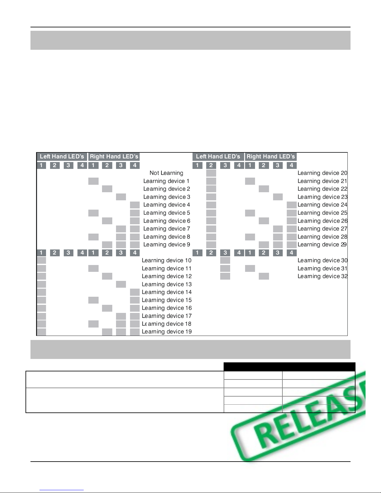
Standalone Mode
All devices can be learnt directly to the receiver. Device attributes cannot be changed when learning devices
in this mode, all devices will use their factory default.
To initiate the learn sequence press the Function Switch on the receiver see page 5. The right hand LED 1 will
illuminate, keep pressing the learn switch until the correct LED sequence is seen for the device that you want
to add to the system.
Free device slots are indicated by the corresponding LED’s flashing, if the LED’s do not flash then that slot is
already occupied by another device. Depress the Learn switch on the device and insert the battery. Repeat
this sequence for subsequent devices.
Once complete devices should be learned to the control panel using the relevant instructions for your control
panel and firmware;
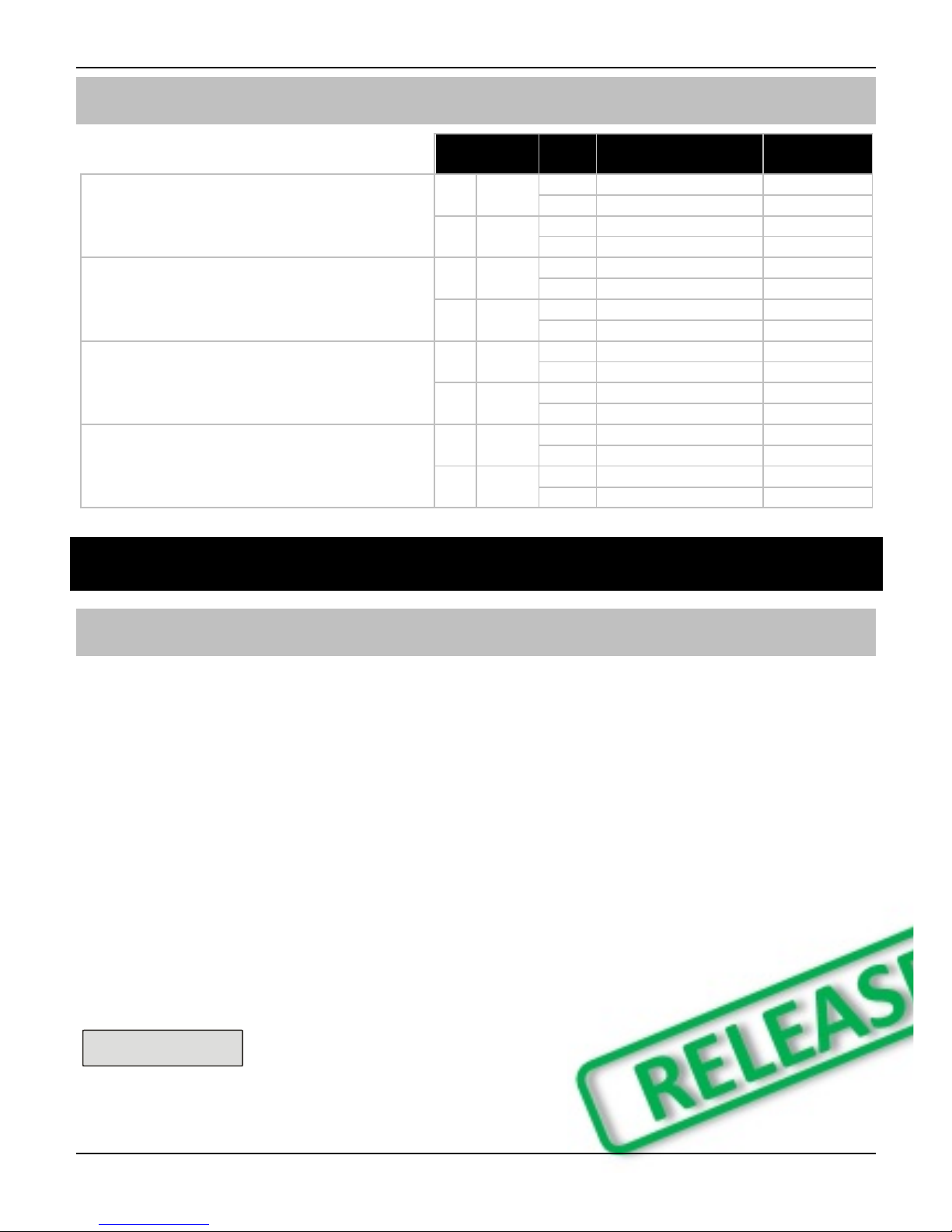
Standalone Operation
Output
Node Status
Nodes can be learnt and deleted using the simple Function
Switch and LED display.
Off
Secure
On
Alarm
Eight Transistor outputs are provided which indicate the status
of nodes 1-16.
Flashing (1Hz)
Trouble
Flashing (4Hz)
Alarm and Trouble
Blinking
Poll Error
Premier Elite 32XPH-W Installation Instructions
INS732 13
This table shows two example systems.
Output
Node
8 Zone SL350 System
8 Zone PIR
System
The outputs indicate a logical OR of the alarm
and trouble signals from both zones.
1
OR {
1
Zone 1 SL350 RX
Zone 1 PIR
2
Zone 1 SL350 TX
Empty
2
OR {
3
Zone 2 SL350 RX
Zone 2 PIR
4
Zone 2 SL350 TX
Empty
This can be used to directly interface with a
simple annunciation type system without the
need for a control panel.
3
OR {
5
Zone 3 SL350 RX
Zone 3 PIR
6
Zone 3 SL350 TX
Empty
4
OR {
7
Zone 4 SL350 RX
Zone 4 PIR
8
Zone 4 SL350 TX
Empty
Option switch 1:
Disables outputs and enables learning using the
Function Switch
5
OR {
9
Zone 5 SL350 RX
Zone 4 PIR
10
Zone 5 SL350 TX
Empty
6
OR {
11
Zone 6 SL350 RX
Zone 4 PIR
12
Zone 6 SL350 TX
Empty
Option switch 2:
Configures outputs to be momentary. When off,
outputs latch and may be cleared using the
Function switch.
7
OR {
13
Zone 7 SL350 RX
Zone 4 PIR
14
Zone 7 SL350 TX
Empty
8
OR {
15
Zone 8 SL350 RX
Zone 4 PIR
16
Zone 8 SL350 TX
Empty
6. Ricochet Diagnostics
Premier Elite V2.XX
Engineer Utilities now includes a new Ricochet Diagnostics menu. This menu displays information about the
live system.
Devices
For Devices the following information can be viewed:-
Routeing
RSSI
Alarms and Status
Device visibility
Time since last message
The /key can be used ti move between the options for each Zone.
Interpreting Keypad Displays
Routeing
The image below shows that Zone 009 is routeing through 14 and then 7 to the expander. If question marks
appear in the display it means the information is not available.
Zone 00 PR
->04->007->P
RSSI
Each value in the image below represents the RSSI levels in dBm (on V2 it is shown as %) at each of the
hops. If question marks appear on the display it means the information is not available.
Premier Elite 32XPH-W Installation Instructions
14 INS732
Zone 00 PR
6>> 80>> 57 P
@
If question marks appear it could be because either the system has just been powered up and information has not
been collected yet, or on large systems the information is not in memory. To populate the display activate the
device and the information should appear.
Device Messages
Zone 00
Not Ricochet
The chosen zone does not have a Ricochet device learned to it.
Zone 00 PR
Msg ??? mins ago
shows the last time the device communicated this represents the last message and could be
a poll, activation or tamper etc.....
Zone 00 PR
>hr since msg
This is a warning showing that the last communication from the device was over an hour ago.
Zone 00 PR
No msg recvd yet
This display shows that no message has been received yet, this would normally be seen on a
recently powered up system, wait 15 minutes from power up before checking the diagnostics
information.
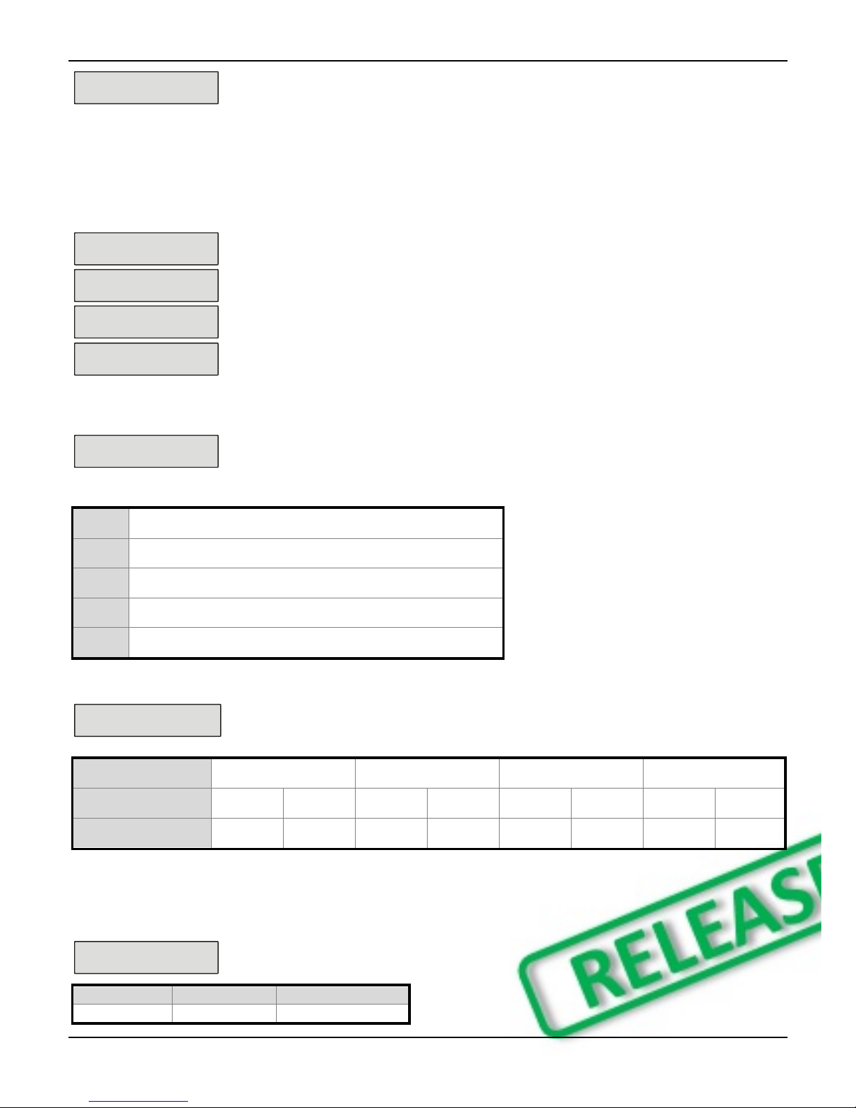
Signal Security™
Zone 00 Shock
????
This display shows information relating to signal security on an 8XP-W. 4 windows are
available to show information; each window represents two devices, (Odd & Even device
slots). Each window could show any of the information detailed in the table below
?
No information is available
_
The chosen device cannot “see” either of the devices
O
The chosen device can see the ODD device(s)
E
The chosen device can see the EVEN device(s)
B
The chosen device can see BOTH devices
Example
Zone 00 Shock
_OEB
In this example Zone 9 can see the devices as detailed below, use the scroll key to
view information about other devices:-
Display
_
O
E
B
Device
1
2
3
4
5
6
7
8
Can see
On the 32XPH-W there are 16 windows to show information from the 32 devices of the system; the format is the
same.
Device Status
Zone 00 Shock
Status: aaaSpdtt
Secure/OK
Active/Fault
Type
a
A
Mag1

Premier Elite 32XPH-W Installation Instructions
INS732 15
a
A
Mag2/Sho
a
A
Reed/PIR
s
S
Poll/Supervision
p
P
Power/Battery
d
D
Device
t
T
Rear
t
T
Front
Ricochet Diagnostics Menu
Engineer tils
View Event Log
YES to Select:-
Engineer tils
y
U
Zone 00 Shock
Status: aaaSpdtt
?
Zone 00 Shock
->???->???->P
Zone 00 Shock
??>> ??>> ?? P
C
Zone 00
Not Ricochet
C
BB
ser000 Ricochet
Not Ricochet
U
?
ser002 Ricochet
Not connected
@
Zone 00 Shock
????????????????
C
Zone 00 Shock
>hr since msg
C
C
ser002 Ricochet
->P
ser002 Ricochet
->> P
C
@
ser002 Ricochet
Logon Bat OK
C
C
RYES to erase
unknown keyfobs
y
sPNetwork , P 0
Devices: 08
LL.H..M.
y
U
U
NN
NN

Premier Elite 32XPH-W Installation Instructions
16 INS732
Premier Elite V3.XX
Low signal security
For V3 the keypad can display basic signal security information for each device on an expander. Each device will show
H High, M Medium or L Low signal security. The system is updated live and therefore it is possible to determine
changes by moving devices, or by adding more to the system. The information displayed replicates what is seen when
using Ricochet Monitor.
Low Signal Security Displays
The network, expander and number of devices learnt to the expander will be shown.
Use the key to select the expander you wish to view.
No devices learnt to the expander. 8 spaces available.
2 devices out of eight learnt showing Low signal security. Adding more devices will
improve the reading, moving them will not.
8 devices on the system, 2 show Medium signal security. 6 showing Low signal
security. Moving the devices may improve the system.
8 Devices learnt to the system, all devices showing High signal security, the system
is operating perfectly.
7. Modes of Operation
Commission Mode
Expander
The expander has a Commission Mode, which when operated ensures secure communications with devices
on the system. Commission Mode is automatically enabled when the expander is in tamper. When in
commission mode the RF signal is attenuated by -6 dB, and will reject weak signals. This means that when
devices are placed into their final locations and communications are established, you can be sure that the
signal path is secure, and robust.
After entering Commission Mode the expander will also instruct the devices to poll in every 4 minutes, rather
than the standard 15 minute poll time. The instruction will be sent with the next available poll to the device.
Device Commission Mode
At any time, when a tamper is generated on a device it will enter commission mode, the devices will do this
regardless of the state of the receiver. Closing the tamper circuit will activate the LED for a short period of time
whilst communication with the receiver is established.
The LED will flash, indicating the device is trying to communicate with the receiver, once communication is
successful the LED will come on solid and then go out.
If the LED does not flash but simply comes on solid when the tamper is closed, then a valid & secure
communication has taken place. If the LED flashes and then goes out, without going solid communication
has failed.
This method of commissioning devices ensures that valid and secure communication is taking place and that
signals are reaching the receiver. It is recommended that Device Commission Mode is used in conjunction
with Expander Commission Mode. See Above.

Premier Elite 32XPH-W Installation Instructions
INS732 17
8. System Attributes
Polling
Polling occurs between the devices and the receiver at a pre-determined interval of 15 minutes. This helps to
conserve battery life. Poll intervals are set to 4 minutes when the system is in Commission Mode. Please see
page 16 for details. The standard poll time is not adjustable. If the system is powered down for more than 1
hour, the devices will go into an Offline Mode to conserve battery life, in this case it can take up to 2 hours for
all devices to come back online, alternatively each device should have its tamper circuit opened to force
communications. When forcing the devices to come back online the same setup principles should be used
and devices closest to the receiver should be activated first, this will again allow the mesh network to be
established.
System Devices
Auto Mode
When in Auto Mode, devices poll at 15 minute intervals. Following activation, devices will not transmit the
same activation again for a period of 3 minutes.
Always Awake
This mode should only be used on devices which are required to signal at all times and is the default setting
for the Impaq Contact-W and Impaq Plus-W. For example a Impaq Contact-W on a door which you need to
know is opened, regardless of system state; or devices such as PA buttons & smoke detectors which have
been connected to the inputs of the Magnetic Contact. The number of devices on a system in this mode
should be kept to a minimum.
Device Specific
This mode is assigned to devices that need to operate in a specific way and should not be changed. Life
safety devices and sounders will typically use this mode.
Hybrid Mode (V2.xx)
Hybrid mode is used to control the reporting functions for devices. When in this mode devices are asleep
when the system is unset, and are woken up by the control panel at the point of arming. When the system is
disarmed the devices will be put back to sleep.
Expander O/P Mode
Expander O/P modes are for future use and should not be used with any of the devices listed above.
On very large systems (100 devices +) a small delay may be experienced when arming the system, this is normal
as the expanders on the system wake up the relevant devices.
Premier Elite DT-W should ALWAYS be used in Hybrid mode, failure to do this will have an adverse effect on
battery life.
as this is a dynamic bi-directional system any device which is Always Awake has the capability to shorten battery
life of other devices.

Premier Elite 32XPH-W Installation Instructions
18 INS732
Premier Elite 32XPH-W Power Loss
If the power to the receiver is lost for more than one hour, all devices on the system will enter an “Offline”
mode to preserve battery life.
When power is replied to the receiver it can take up to two hours for all devices to be recognised by the
system. To resolve this issue quickly each device on the system should be tampered to force communication
with the receiver.
The same principles apply to the learning & placing of devices, and as such tampering should start with the
device closest to the receiver and working outwards, allowing for the mesh network to be re-established.
9. Specifications
Electrical
Operating Voltage
10 - 13.7VDC
Current Consumption
<100mA average, 350mA peak (<100ms)
Network
4-wire standard 7/0.2 alarm cable up to 250m. Star, Daisy Chain or
any combination.
Outputs 1 - 8
Open Drain. 300mA, 30V Max
Operating Temperature
-10C (+14F) to +50C (+122F)
Storage Temperature
-20C (-4F) to +60C (+140F)
Maximum Humidity
95% non-condensing
EMC Environment
Residential, Commercial, Light Industrial
or Industrial
Physical
Dimensions
170mm H x 140mm W x 35mm D
Packed Weight
500gms
Standards & Directives
Texecom declares that this product complies with the requirements of the following directives
2011/65/EU ROHS Directive
Standards
FCC CFR 47 Part 15 SubPart C
IEC 60950-1:2005/A2:2013
IEC 62311:2007
Product Type
Frequency
LAIA5000
920MHz
FCC ID: MYJLAIA5000
FCC warning statement:
This device complies with Part 15 of the FCC Rules.
Operation is subject to the following two conditions:
(1) This device may not cause harmful interference, and
(2) This device must accept any interference received, including interference that may cause undesired
operation.
This equipment complies with FCC radiation exposure limits set forth for an uncontrolled environment. End
users must follow the specific operating instructions for satisfying RF exposure compliance. This transmitter
must not be co-located or operating in conjunction with any other antenna or transmitter.

Premier Elite 32XPH-W Installation Instructions
INS732 19
Warning: Any Changes or modifications not expressly approved by the party responsible for compliance
could void the user's authority to operate the equipment.
Notice to OEM customer: Where this product is provided as part of a solution to an end user for use within
the USA, the above FCC ID and warning must also be included in the User / Installers instructions.
Please note the device should not be used with 20cm of the human body when the RF is enabled
Warranty
All Texecom products are designed for reliable, trouble-free operation. Quality is carefully monitored by
extensive computerised testing. As a result the Premier Elite 32XPH-W expander is covered by a two-year
warranty against defects in material or workmanship.
As the Premier Elite 32XH-W expander is not a complete alarm system but only a part thereof, Texecom
cannot accept responsibility or liability for any damages whatsoever based on a claim that the Premier Elite
32XPH-W expander/s failed to function correctly. Due to our policy of continuous improvement Texecom
reserve the right to change specification without prior notice.
Premier, Premier Elite, Ricochet & SignalSecurity are trademarks of Texecom Ltd.
© TEXECOM LTD 2016

Texecom Limited, Bradwood Court, St. Crispin Way, Haslingden,
Lancashire BB4 4PW, England.
Technical Support:
UK Customers Tel: 08456 300 600
(Calls charged at local rate from a BT landline. Calls from other networks may vary.)
International Customers Tel: +44 1706 233875
Email: techsupport@texe.com
© Texecom Limited 2016
INS732
Table of contents
Popular Receiver manuals by other brands


ALLO
ALLO SEA SIGN.BOX UNI instructions

RCS AUDIO-SYSTEMS
RCS AUDIO-SYSTEMS UBT-016 operating instructions

Yamaha
Yamaha RX-V467BL Quick reference guide

Triax
Triax HTX 1V operating manual

star sat
star sat SR-X1200D user manual

Audio Control
Audio Control ACTIVE-BALANCED BVR-20 Installation and operation manual