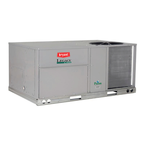
TGM CTV14CN018A User manual

Technical Manual
R410A 60Hz 14 SEER Top-Discharge
Heat Pump Outdoor
1

R410A 60Hz Universal Outdoor Series Technical Manual Outdoor Unit
Part 1. General Information
1. Model Names of Indoor/Outdoor Units 3
2. External Appearance 4
3. Features 5
Part 2. Indoor Unit 6
1.Features 7
2.Dimension 9
3.Service Space 10
4.Wiring Diagrams 11
5. Electric Characteristics 13
6. The Specification of Wiring 14
7. Field Wiring 15
Part 3 Outdoor Unit 16
1. Dimension 17
2. Service Space 18
3. Wiring Diagrams 19
4. Electric Characteristics 20
5. Operation Limits 21
6. Sound Levels 22
7. Refrigerate diagram 23
Part 4 Installation 24
1. Precaution on Installation 25
2. Vacuum Dry and Leakage Checking 26
3. Additional Refrigerant Charge 28
4. Insulation Work 29
5.Test Operation 31
Part 5 Unit maintenance 32
1. Fault indicator of indoor unit 33
2. Fault indicator of outdoor unit 34
3.Flow chart of troubleshooting 35
4. Exploded views and part list 40
2

14SEERAIRHANDLERSYSTEMTECHNICALMANUAL
Part 1. General Information
1. Model Names of Indoor/Outdoor Units
1.1 Indoor Units
Model name
Dimension(W×H×D)(inch)
Power supply
SEER 14 Cooling Only & Heat Pump
CTA14C018A
19-2/3×45-3/4×22
208~230V-1Ph-60Hz
CTA14C024A
19-2/3×45-3/4×22
208~230V-1Ph-60Hz
CTA14C030A
19-2/3×45-3/4×22
208~230V-1Ph-60Hz
CTA14C036A
19-2/3×45-3/4×22
208~230V-1Ph-60Hz
CTA14C042A
19-2/3×45-3/4×22
208~230V-1Ph-60Hz
CTA14C046A
22×53-1/8×24-1/2
208~230V-1Ph-60Hz
CTA14C060A
22×53-1/8×24-1/2
208~230V-1Ph-60Hz
1.2 Outdoor Units
Model name
Dimension (W×H×D) (inch)
Power supply
SEER 14 Cooling Only & Heat Pump
CTV14HN018A
21-5/6×25×21-5/6
208~230V-1Ph-60Hz
CTV14HN024A
21-5/6×25×21-5/6
208~230V-1Ph-60Hz
CTV14HN030A
21-5/6×25×21-5/6
208~230V-1Ph-60Hz
CTV14HN036A
29-1/8×25×29-1/8
208~230V-1Ph-60Hz
CTV14HN042A
29-1/8×32-5/6×29-1/8
208~230V-1Ph-60Hz
CTV14HN046A
29-1/8×32-5/6×29-1/8
208~230V-1Ph-60Hz
CTV14HN060A
29-1/8×32-5/6×29-1/8
208~230V-1Ph-60Hz
3

14SEERAIRHANDLERSYSTEMTECHNICALMANUAL
2. External Appearance
2.1 Indoor unit
2.2 Outdoor unit
Note: Standard outdoor unit is using plastic grill. Metal grill can be customized.
4

14SEERAIRHANDLERSYSTEMTECHNICALMANUAL
4. Features
4.1 Operation features
• Long Piping & Cost Effective
• Low noise operation, as low as 57dB(A)
• 24V control, time delay relay, fan relay and transformer included.
4.2 Performance features
• AHRI Certified & ETL listed.
• R410A environment friendly refrigerant.
• Wide operation temperature range:Cooling: 64⁰F-109⁰F; Heating: 20⁰F-109⁰F
• Continuous Cooling Transformation Inner-grooved tube has high thermometric conductivity.
4.3 Reliability features
• Painted galvanized steel cabinet.
• Well-known brand fixed compressor, reliable quality.
• Condenser coils constructed with copper tubing and enhanced aluminum fins.
• 3-speed direct drive motors, provide selections of air flow to meet desired applications.
• Intelligent defrost programs, unit will choose different defrost program according to real
condition.
5

14SEERAIRHANDLERSYSTEMTECHNICALMANUAL
1. Features
(1) “A” shape coils, constructed with copper tubing and enhanced aluminum fins.
(2) Direct drive motors, 3 speed, provide selections of air flow to meet desired applications.
(3) φ10″large fan blade that has powerful wind speed, and the motor is covered with insulation
material, which can ensure that the motor runs in a safe state.
(4) Use TXV as throttle device (14 SEER air handler)
7

14SEERAIRHANDLERSYSTEMTECHNICALMANUAL
(5) Detachable air filter for cleaning or renewal
Versatile 4-way convertible design for vertical up airflow, horizontal right airflow.
8

14SEERAIRHANDLERSYSTEMTECHNICALMANUAL
2. Dimension
9

14SEERAIRHANDLERSYSTEMTECHNICALMANUAL
3. Service Space
The indoor unit should be installed in a location that meets the following requirements:
INSTALLATION NOTES: .
1. When up hand discharge , how to trap or plug all drains is see the left Figure.
2. When right hand discharge , how to trap or plug all drains is see the top Figure.
3. The seal-plugs are supplied as accessories , and be screwed tightly only with hand.
10

14SEERAIRHANDLERSYSTEMTECHNICALMANUAL
4. Wiring Diagrams
18K/24K/30K/36K/42K
48K
11

14SEERAIRHANDLERSYSTEMTECHNICALMANUAL
60K
12

14SEERAIRHANDLERSYSTEMTECHNICALMANUAL
5. Electric Characteristics
Model
Indoor Units
Indoor Fan Motor
Hz
Voltage
Min.
Max.
kW
SEER 14 Cooling Only
CTA14C018A
60
208-230V
198V
242V
0.18
CTA14C024A
60
208-230V
198V
242V
0.21
CTA14C030A
60
208-230V
198V
242V
0.29
CTA14C036A
60
208-230V
198V
242V
0.40
CTA14C042A
60
208-230V
198V
242V
0.46
CTA14C046A
60
208-230V
198V
242V
0.58
CTA14C060A
60
208-230V
198V
242V
0.58
13

14SEERAIRHANDLERSYSTEMTECHNICALMANUAL
6. The Specification of Wiring
Note:
The cross-section areas of wires or lines should not be less than the corresponding ones
listed in the table below;Besides, if the power wires is quite long from the unit, please choose
the windings with larger cross-section area to guarantee the normal power supply.
Model
Type
Indoor power
wiress
Thermostat communication wiress
Outdoor power
wiress
Indoor
Outdoor
18 K series
(single phase)
Cooling only
3*1.0mm²
3*0.75mm²
2*0.75mm²
3*1.0mm²
24 K series
(single phase)
Cooling only
3*0.75mm²
2*0.75mm²
3*2.5mm²
30 K series
(single phase)
Cooling only
3*0.75mm²
2*0.75mm²
36 K series
(single phase)
Cooling only
3*0.75mm²
2*0.75mm²
42 K series
(single phase)
Cooling only
3*0.75mm²
2*0.75mm²
3*4mm²
48 K series
(single phase)
Cooling only
3*0.75mm²
2*0.75mm²
60 K series
(single phase)
Cooling only
3*0.75mm²
2*0.75mm²
14

14SEERAIRHANDLERSYSTEMTECHNICALMANUAL
7. Field Wiring
1. To avoid the electrical shock, please connect the air conditioner with the ground lug.
The main power plug in the air conditioner has been joined with the ground wiring,
please don't change it freely.
2. The power socket is used as the air conditioner specially.
3. Don't pull the power wiring hard.
4. When connecting the air conditioner with the ground, observe the local codes.
5. If necessary, use the power fuse or the circuit, breaker or the corresponding scale
ampere.
15

14SEERAIRHANDLERSYSTEMTECHNICALMANUAL
Part 3 Outdoor Unit
1. Dimensions 17
2. Service Space 18
3. Wiring Diagrams 19
4. Electric Characteristics 20
5. Operation Limits 21
6. Sound Levels 22
7.Refrigerate diagram 23
16

14SEERAIRHANDLERSYSTEMTECHNICALMANUAL
1. Dimension
17

14SEERAIRHANDLERSYSTEMTECHNICALMANUAL
2. Service Space
18

14SEERAIRHANDLERSYSTEMTECHNICALMANUAL
3. Wiring Diagrams
SEER 14 Cooling only
19

14SEERAIRHANDLERSYSTEMTECHNICALMANUAL
4. Electric Characteristics
Model
Outdoor Unit
Hz
Voltage
Min.
Max.
Outdoor
motor (kw)
CTV14CN018A
60
208~230V
198V
242V
0.15
CTV14CN024A
60
208~230V
198V
242V
0.18
CTV14CN030A
60
208~230V
198V
242V
0.21
CTV14CN036A
60
208~230V
198V
242V
0.21
CTV14CN042A
60
208~230V
198V
242V
0.21
CTV14CN046A
60
208~230V
198V
242V
0.51
CTV14CN060A
60
208~230V
198V
242V
0.51
20
This manual suits for next models
6
Table of contents
Popular Heat Pump manuals by other brands

Daikin
Daikin Altherma 3 GEO EGSAH06DA9W installation manual

DURASTAR
DURASTAR DRA1U30S1A installation manual

Panasonic
Panasonic WH-SHF09F3E8 Series Service manual

XtremepowerUS
XtremepowerUS 75217 owner's manual

Roller
Roller Silent-Line WPV Series Mounting instructions

Bard
Bard WH421D Series installation instructions

Airwell
Airwell HRW 019 Installation and maintenance manual

Nortek
Nortek GKU18USV4DH Installation instructions & owner's manual

Carrier
Carrier 38QE installation instructions

Sime
Sime ECOMAXI 90 ErP manual

evoheat
evoheat Evo Flex Installation & operation manual

GE
GE Zoneline AZ91H18E E Series owner's manual