Kokido K2O K880BX/EU Troubleshooting guide


1
Table of Contents
1. What Heat Pump is?
3
What it Composes
3
How it works
3
Main characteristics
4
2. Know more about your Heat Pump
5
Safety Features
5
Technical Data
5
Circuit diagram
7
3. Installation (Instruction and Notice)
8
Inspection of your heat pump
8
Choose a good location for installation
8
Electrical Connection
10
Water Flow and Piping Connection
10
Typical Pool Heater Installation Layout
12
Filtration System Layout
12
Multiple Heat Pump Connection
14
Instruction and Notice for Installation
15
Safety Caution
15
4. Operation Instruction
16
Meaning of index lights
16
Meaning of LED display
17
Parameter Code
19
Operating principle
22
Start-Up
25
Tips to save cost ( Using Pool Cover)
26
5. Maintenance
26
6. Troubleshooting
28
7. Warranty
29

2
Table des matières
1. Qu’est-ce qu’une pompe à chaleur ?
30
Ce qui la compose
30
Comment ça marche
30
Principales caractéristiques
31
2. En savoir plus sur votre pompe à chaleur
32
Sécurité
32
Données techniques
32
Schéma du circuit
34
3. Installation (Instruction et Notice)
35
Inspection de votre pompe à chaleur
35
Choisir un endroit approprié pour l’installation
35
Connexion électrique
37
Circuit et Connexions Hydrauliques
37
Schema d’installation typique
39
Schéma d’installation du système de filtration
39
Connexion multiple de pompe à chaleur
41
Instructions d’installation
42
Instructions de sécurité
42
4. Instruction de mise en route
43
Signification des voyants lumineux
43
Signification de l’affichage des LED
44
Code paramètre
46
Principe de fonctionnement
50
Mise en route
53
Astuces pour consommer moins d’énergie (en utilisant une bâche)
54
5. Entretien
55
6. Problèmes et solutions
57
7. Garantie
58

3
1. What Heat Pump is?
What It Composes
A water heater is basically composed of a compressor, an evaporator, some capillary or expanding
valves and a condenser.
How it works
Heat pumps use electricity to capture heat and move it from one place to another. They don't
generate heat. As the pool pump circulates the swimming pool's water, the water drawn from the pool
passes through a filter and the heat pump heater. The heat pump heater has a fan that draws in the
outside air and directs it over the evaporator coil. Liquid refrigerant within the evaporator coil absorbs
the heat from the outside air and becomes a gas. The warm gas in the coil then passes through the
compressor. The compressor increases the heat, creating a very hot gas that then passes through
the condenser. The condenser transfers the heat from the hot gas to the cooler pool water circulating
through the heater. The heated water then returns to the pool. The hot gas, as it flows through the
condenser coil, returns to liquid form and back to the evaporator, where the whole process begins
again.
Example of how a heat pump operates.

4
Main characteristics
Efficient and economical
The unit's Coefficient of Performance (cop) ≥4.0. In comparison, an electric boiler (cop) ≤0.95, a gas
or oil boiler (cop) is about 0.5--0.8, a coal-boiler (cop) is only about 0.3--0.7.
Safety ensured
When the unit is working, all electrophorus parts are absolutely isolated from circulating water, thus
avoiding some possible dangers such as explosion, dry heating, gas poisoning, which may happen
with a common water heater.
Environmentally friendly
The applied refrigerant is not Freon, and when the unit is working, no waste water, no waste residue,
no waste heat and no waste gas will pollute the circumstance.
Installation convenient
It can be installed at outdoor area, balcony, flat roof, carbon, equipment floor, and does not need
special room only for it.
Modularized control function
You can combine several units to make one heat water supply system controlled by modularization.
The system can adjust the running time and order automatically, by which the whole system can run
efficiently, and every unit's total running time can be unified.
Operation convenient
The unit is controlled by microcomputer. According to the condition of water temperature and circular
water volume, the unit will adjust itself. There is no need for anybody to keep on watching it.
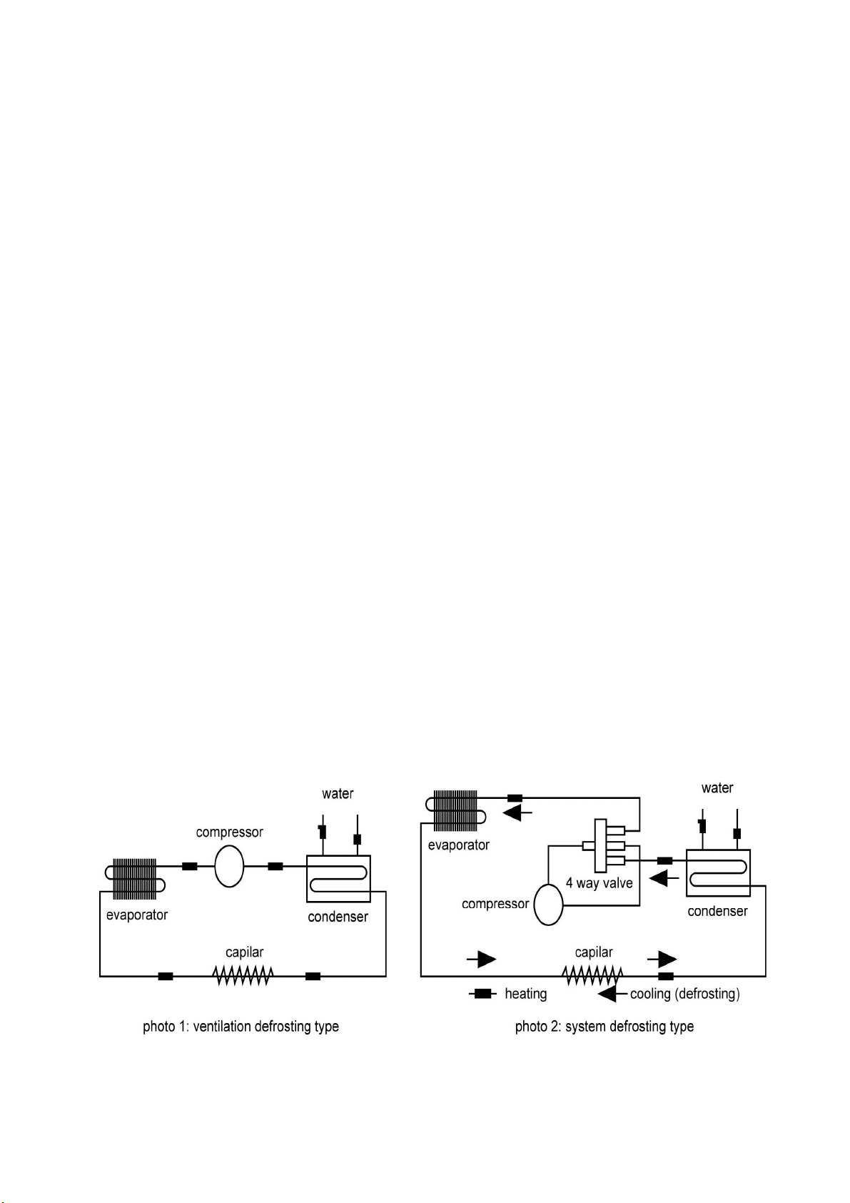
Automatic defrost function
With intelligent zed defrost function, you can set defrost condition according to different climates to
make the unit defrost in a flexible way.
Far-ranging applicability
Can be used in hotel, bathe centre, school, factory, indoor natatorium and so on.

5
2. Know more about your Heat Pump
Safety Features
Time Delay. All models are preset at 3 minutes compressor time delay (F21 Parameter code in LED
display) to prevent the compressor from breaking by frequent boot. In addition, the controller doesn’t
boot the compressor within 3 minutes after turning on the power supply, thus it can also be protected
in the state of power being off and on in short time.
Water Pressure Switch
.
Heater will stop if water pressure is lower than operating level at 0.1kg/cm
2
. It
will restart automatically after backing to normal pressure.
High/Low refrigerant pressure switch. Heater will stop when refrigerant pressure is unsafe reaches
4.1MPa or 0.15 MPa. It will restart automatically after backing to normal pressure.
Technical Data
MODEL
K880 K881 K882 K883 K884 K885
BTU/H
8500 14000 22000 29000 34000 43000
HEATING
CAPACITY W 2500 4200 6500 8500 10000 13000
POWER INPUT
W 500 850 1300 1700 2000 2600
EFFICIENCY COP 5 5 5.08 5 5 5.08
STATED
CURRENCY A 2.3 4.1 6.8 8.3 9.2 12.0
POWER INPUT
V/PH/HZ
220/1/50 220/1/50 220/1/50 220/1/50 220/1/50 220/1/50
COMPRESSOR
QUANTITY
1 1 1 1 1 1
COMPRESSOR
TYPE
ROTARY ROTARY ROTARY ROTARY ROTARY ROTARY
HEAT
EXCHANGER
PVC HERMETIC WATER BARREL WITH PIRAL OFT TITANIUM PIPE IN IDE

6
REFRIFERANT
R410A
BLOWER
QUANTITY 1 1 1 1 1 1
FAN POWER
INPUT W 15 20 30 45 95 95
FAN ROTATE
SPEED RPM 850 850 1050 850 1050 1050
BLOWER
STYLE LATERAL-BLOW WITH IN TALLED HORIZONTAL
NOISE LEVEL
dB(A)
45 47 47 51 55 58
WATER
CONNECTION
mm 50 50 50 50 50 50
WATER FLOW
m3/h ≥4.0 ≥4.0 ≥4.0 ≥5.0 ≥6.0 ≥7.0
WATER
PRESSURE
LOSS
kPa 8 10 10 10 12 12
NET
DIMENSION
mm
710x320x500
710x320x500
760×320×500
910×360×650
910×360×650
910×360×650
WEIGHT
NET/GROSS Kg 35/45 45/55 50/60 73/85 75/87 78/90
Fuse gauge A 16 16 16 20 32 32
Residual
current
limit
mA 20 25 25 30 45 45
Supply gauge
mm
2
3*1.5 3*1.5 3*1.5 3*2.5 3*2.5 3*2.5
NOTE: Rated condition: Circumstance dry bulb temperature : 24
℃
, Inlet water temperature:27
℃

7
Electric circuit diagram

8
3. Installation (Instruction and Notice)
WARNING!
Installation made by unqualified persons can result in hazards to the installer and others. The
information contained throughout the “Installation” section is intended for use by qualified heat
pump installation technicians, familiar with the swimming pool/spa service industry safety
standards and methods. Installation to be performed by qualified individuals only.
Inspection of your heat pump
Upon receipt, inspect the carton and their contents for damage due to transit. If damage has been
incurred and is suspected, bring it to the immediate attention of the delivering carrier.
Upon arrival at the installation site, the unit should be carefully unpacked and again inspection for any
damage that may have occurred in transit. Also, check unit data plate to make sure you have the
proper model before installing.
Choose a good location for installation
To make heat pump works more efficient, the installer should take account into following conditions.
The heat pump will perform more efficiently when placed in direct sunlight
The heat pump should be located on a solid, level surface (concrete or fabricated slab) and
ideally with itched surface that allows proper drainage of condensation and rain water from the
base of the unit. If possible, the pad should be placed at same level or slightly higher than the
filter system equipment pad.
To allow for ample air intake and prevent re-circulation, proper clearance around the entire heat
pump is desired. Moreover, it should have proper clearance for accessing service panels.
However, each installation must also be evaluated, taking into account the prevailing local
conditions such as proximity and height of walls, and proximity to public access areas.

9
Suggested clearance:
The heat pump should not be placed near sprinkler systems, especially those where fertilizer is
added. This is very corrosive and over time will severely damage the unit.
For installation site is an ocean front area, the heat pump should be placed out of direct spray of
sand and salt which may clog, damage and corrode the unit. Proper protection like fence is
recommended to be built between the unit and the prevailing beachfront wind.
Minimum distance between the heat pump and the rim of the swimming pool must be , at
least 3.5m
The heater should be placed on a solid surface sufficient above grade to prevent
water from entering it, and allowing condensate to drain from base.
The installation of the heater in a fully enclosed area is not recommended.

10
Electrical Connection
WARNING!
RISK OF ELECTRICAL SHOCK OR ELECTROCUTION. The electrical supply to this product
must be installed by a licensed or certified electrician in accordance with applicable national and
local codes and ordinances. Improper installation may cause electrical hazard, which could result
in death or serious injury to pool or spa users, installers or others, and may also cause damage
to property. Read and follow the specific instructions inside this manual.
DISENGAGE MAIN POWER DISCONNECT BEFORE ATTEMPTING INSTALLATION.
Suitable electrical supply line. See rating label on the unit for electrical specification.
Electric cut-out (Disconnect) switch that will interrupt all power to the unit. This switch must be within
line of sight of the heat pump.
Watertight conduit to run the electrical supply line.
Power supply for the heat pump must come, preferably, from a sole circuit provided with
standard-issue protection components and a magnetic circuit breaker.
Water Flow and Piping Connection
Proper water flow is essential to the performance of the heat pump. It requires minimum water flow as
stated in technical data table
.
Make sure filter is clean and there are no obstructions in the filtering
system which decrease the flow rate.
Your heat pump is equipped with water pressure switch which will shutdown the heater if water flow is
too low.
Piping to the heat pump must be in accordance with applicable state and local codes.

11
Heat pump water inlet and outlet hole 50mm. This unit is provided with two 50-38mm hose adaptor for
38mm soft hose connection.
Pipefitting such as tees, elbows and reducers may cause pressure to drop when water flows through
them. Plan the plumbing layout carefully and use as few fittings as possible to connect your heat
pump. (Please see the basic layout included for basic reference).
The heat pump should be connected downstream from the pool pump and filter in the return line to
the pool.
Check valve should be installed in a manner that will not allow the chlorine drain back to the heat
pump when the water pump is off.
Excess water flow will damage the heat exchanger
After the piping installation is completed, should test the piping system (water leakage) by operating
the filter with the heat pump off. Observe any abnormalities and obstructions in the filtering system.
A detachable connection (Union) should be used adjacent the heat pump to facilitate servicing and
winterizing the unit.
Open circuit with hot water
Closed circuit without hot water

12
Filtration System Layout
Shared Filtration System

13
Independent Filtration System

14
Multiple Heat Pump Connections
All plumbing on multiple heat installations must be done in parallel .An equal flow of water to each
heat pump is important for optimum operation.

15
Instructions and notice for installation
The place which the unit is installed must be sturdy and able to withstand its weight. If not, it is
possible that the unit fall off and be destroyed.
The electrical system must comply with the local regulations and rating data in the technical
sheet, and the power supply must be separate.
If installed out of way, the unit can not run well and could be damaged.
Such as low voltage or the power type is wrong, it will raise unit electric leakage and burning.
The unit must effectively ground and connected reliably to the mains by wiring of adequate size.
If grounding is not well, it will arise fire or get an electric shock.
After the pipe systems was installed, they must be washed cleanly before connect with the units.
The pipe systems must be tested for compression resistance in order to check whether there is
any leakage.
It must be possible to leave room around the unit for air flow and any maintenance operations
that may be necessary.
The coagulation produced by unit can be removed easily.
Safety Cautions
Attention: It is not allowed that the water level is too low.
Don't restart the unit again and again; you must wait 5 minute to restart it.
If the water pump doesn't work, turn off it immediately.
Please cover the unit to keep out dust if no using for long time.
Please clean the evaporator by professional means timely .If the unit has worked for a long
time, there could be more dust in the evaporator coil, and the airflow volume will decrease.
To have a comfortable efficiency, don't set the temperature too high or too low.
Do not use unit near heater, fires or in the vicinity of flammable liquids and the place smeary.
Do not insert finger or others into place with a draught, it will do hurt to you.
Do not repair the unit yourself, please contact profession when the unit displays error code.
Do not spray flammable chemicals around unit to avoid fire.

16
4. Operation Instruction
Meaning of index lights
Panel:
The function of the LED on the panel is showing below:
Index Light
Name Light Flash
Temp
Setting
In the state of temp
setting
-
- - -
Heat Heating
Ready to heat, in the state of compressor start
delay protection
Defrost Defrosting
Ready to defrost, in the state of compressor start
delay protection
-
Alarm - Alarm state

17
Meaning of LED Display
The LED usually shows temperature, if it shows “SHr”, it means the temperature sensor is short, and
“OPE” means the temperature sensor is open. The temperature and the alarm code (Axx) will show
alternately when in the alarm state.
The code is showing below:
Code
Signification Explanation
A11
External alarm
Alarm from external alarm signal, please refer to the internal
parameter code “F50”. This alarm signal is triggered when the water
pressure is lower than operating level at 0.1kg/cm
2
and/or refrigerant
pressure is out of the range 0.15MPa - 4.1MPa.
A21
Water temperature
sensor error
Open or short
(
showing “OPE” or “SHr”
)
A22
Evaporator sensor error
Open or short
(
showing “OPE” or “SHr” when press the key “↓”
)
A99
Over probation time
If you have set the probation time F87, the alarm occurs when the
accumulative running time is over probation time, and the controller
can not work.
How to set the temperature?
Press the key “set” for at least 2 seconds, then enter the state of temperature setting, here the LED
displays the setting temperature, then using “ ” key or “ ” key can change the parameter
(
the key “ ”adds 0.1°C, the key “ ” minuses 0.1°C, press and hold it over 0.5 seconds
can add or minus rapidly
)
. After setting, press “set” again, then exit the state of parameter setting.
(The setting temp range is limited by the parameters F13 and F14; please refer to the senior
operation). Pressing the key “M” in the setting process means cancel and exit, but the setting value
will not be saved.

18
How to read the temperature of the evaporator sensor?
When displaying current temperature, press “ ” key, Controller will display defrosting
temperature. Release “ ” key, then return to current temperature.
How to look over and adjust the real clock time?
Press the key “Set” to enter the state of displaying time when in the state of displaying temperature.
Press the key “Set” for 2 seconds to enter the state of adjusting time, and press the key “Set” to return
to the state of displaying temperature.
In the state of adjusting time, the hour part of the LED flashes, and you can adjust the hour by
pressing the key “ ” and “ ”, then press the key “Set”, and the minute part of the LED flashes,
you can also pressing the key “ ” and “ ” to adjust the value, then press the key “Set”
again to exit. Pressing the key “M” in the adjusting process means giving up and exiting, but the time
will not be saved.
Advanced Operation
Press the key “M” and hold it for 5 seconds, and if you have set the password, the LED display the
“PAS” to hint you to enter the password, you can use the key “ ” and “ ” to enter the
password, if the password is correct, the LED will display the parameter code (refer to table), use
“ ” or “ ” to select the parameter code
,
Pressing the “set” key can make it to show the
value of the parameter after select the parameter, here you use “ ” or “ ” to set the
parameter(pressing the key and not release can add or minus rapidly), then press the “set” key to
return to the state of showing parameter code after finishing setting. Pressing the key “M” can exit the
parameter setting state when display the parameter code, pressing the key “M” means cancel when
in the process of setting parameter, and the parameter will not be changed.

19
Parameter Code
Internal parameter code is showing below:
Sort Code
Parameter
Name
Range
Factory
setting
Unit Remark
F11
Setting
temperature
F14 – F13 40
℃
The setting range is limited
by F13 and F14
F12
Temperature
difference
0.1 – 20 1.0
℃
Control the temperature
difference, please refer to
the temperature controlling
F13
Max setting
temperature
-45 - +145 40
℃
F14
Min setting
temperature
-45 - +145 10
℃
Notice: the controller will
follow the rule of
F14<F11<F13 forcibly, if
you find out that one
parameter can not be
adjusted, it is because the
parameter is limited by
other parameters, you must
first adjust other
parameters
F18
Evaporator
sensor
adjustment
-20 – +20 0.0
℃
Adjust the evaporator
sensor bias
Temperature
F19
Temp sensor
adjustment
-20 – +20 0.0
℃
Adjust the temperature
sensor bias
Compressor
F21
Compressor
delay time
0 -- 10 3 min
This manual suits for next models
5
Table of contents
Languages:
Popular Heat Pump manuals by other brands

Trane
Trane CXAU Installation, operation and maintenance

Goodman
Goodman GSZ/VSZ 13 SEER Technical manual

Bard
Bard WH421 installation instructions

International comfort products
International comfort products CAS090 G Series installation instructions

Daikin
Daikin VRVIII Operation manual

Daikin
Daikin Super Multi NX FTXG25JV1BW Service manual

Bard
Bard Q-TEC Q24H2 Series installation instructions

York
York YU2E14YEEBMHO-X Service manual

Carrier
Carrier 50ZH Series Guide to operating and maintaining

Daikin
Daikin ERQ125A7W1B installation manual

Daikin
Daikin EHFZ-D3V User reference guide

Haier
Haier MRVII-S AU482FIERA Installation & maintenance instructions