The Corner Fridge Cold Room User manual

CORNER FRIDGE
INTEGRATED COLD ROOM
INSTALLATION AND
OPERATION INSTRUCTIONS
DEFYING
CONVENTION

Contents
Important Information 3
Installation of your Cold Room Pantry 4-6
Step 1 4
Step 2 4
Step 3 4
Step 4 5
Step 5 5
Step 6 5
Step 7 6
Step 8 6
Step 9 6
Operation of your Cold Room Pantry 7
Cleaning and Maintenance 7
Adjusting the Temperature 7
Warranty Information 7

3
Congratulations...
...on your new Integrated Cold Room 600mm x 1200mm Pantry
Please read the instructions thoroughly to understand how to install your Cold Room as well as how to
look after it.
Before you start installing your Cold Room and in fact at the time of delivery, if The Corner Fridge
Company is not installing your Cold Room for you, please make sure you check that the product has
not been damaged during transport.
Any damage must be reported immediately. Both to the transport company that delivered the product
and to The Corner Fridge Company.
Important Information

4
Step. 1
First select the floor, and place where the unit wall will stand.
(Please note that floor and ceiling panels are the same).
Place the floor with the bottom facing upwards and pull
out a little insulation from the large holes. Secure the
attachments for the plinth legs.
Screw the adjustable plinth legs down fully until they
reach the bottom of the plastic cups (Fig. 1).
Step. 2
Position the floor approximately in its final location and
level it by adjusting the plinth legs. (Fig. 2).
Step. 3
Position the unit wall (right/left) and rotate
the lock towards the floor using the allen
key supplied (Fig. 3).
Then secure the other elements to one
another in the same way, and finally fit the
ceiling.
If the hook fails to engage the first time,
it must be turned back fully until it clicks
before it can be rotated into the lock
once more.
Installation of your Cold Room
Below is a step by step guide and the drawings or Figures (Fig) corresponding to each step provided.
We recommend that all internal joints are sealed with silicone.
Fig. 1
Fig. 2
Fig. 3
5
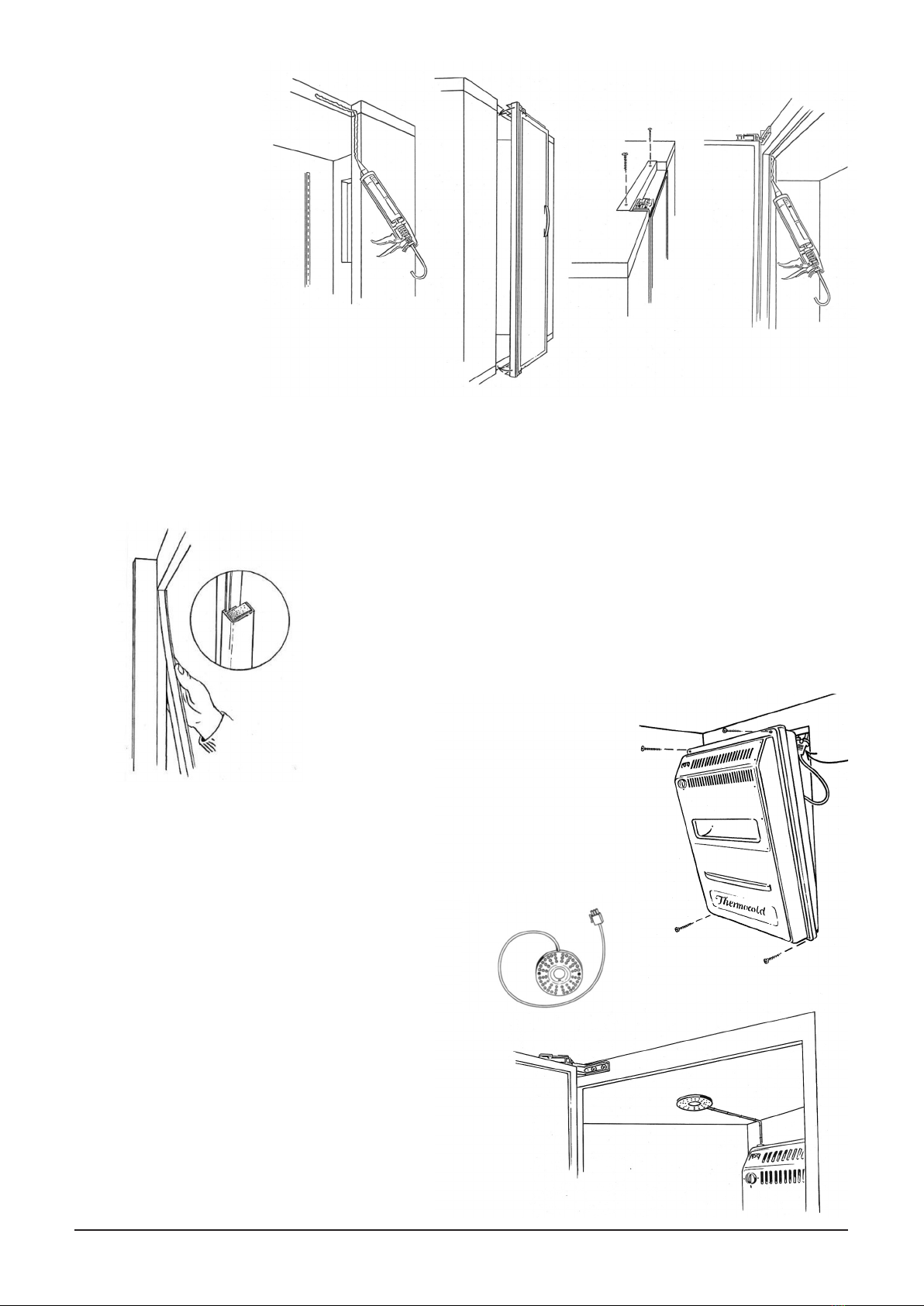
Step 5
Fit the long plastic profile with insulation into the groove on the door frame and
press it into place so that the lip lies against the side wall on both sides. (Fig. 5).
Step 4
Select the hinge
side on the door by
turning the door
frame with the door.
Place the door with the
frame into the opening to
ensure that it fits.
Remove it again and apply
a thick strip of sealant
(cartridge supplied) in the
opening approximately 1cm from
the edge and internally around the
entire door opening.
Insert the door frame with the door and screw
the door frame securely to the ceiling on the upper side.
Seal around the whole frame from the inside,
make sure that it is tight. (Fig. 4).
Step 6
Remove the packaging from the compressor unit and pull
out the power cord.
Lift the unit into the opening, and at the same time pass
the power cord up between the cover on the back.
Carefully screw the unit securely at each corner so that
the gasket on the flange is pressed neatly against the
element wall.
NOTE: Secure the power cord over the ceiling with the
clips supplied, to prevent it from falling into the noise
channel and damaging the fan. (Fig. 6).
Fig. 4
Fig. 5
Fig. 6

6
Step 7
Screw the LED lamp securely to the ceiling at a point about 25 cm in from
the door frame.
Remove the protective tape on the cable conduit/connector bar and press it
securely in place on the ceiling as far as the female connector on the unit.
Then press the cable into the conduit and insert the contact.
Step 8
Place the shelves at the bottom of the cabinet, with the 2 shortest on top (Fig. 8.).
Fit the uprights/brackets onto the back wall using the screws supplied.
Lift the top shelf into the desired position in the cabinet and
then attach the shelf brackets to the uprights just below
the shelf. Repeat the process for the remaining three shelves.
Press the shelves down into the groove to secure them.
Make sure that the second top shelf does not come into
conflict with the dust filter tray on the unit.
NOTE: If the cold room is to be integrated, this should
be done before the shelves are placed in position.
See Step 9.
Step 9 - Integration
The depth of the cover panels and the worktop will determine the distance from the wall at which the cold room must be
positioned.
First fit the finishing panel securely onto the door in the correct position using the Velcro hooks and loops fasteners
supplied.
Drill eight 5 mm holes in the Cold Room door. Screw the finishing panel in place using the 5 mm long screws supplied.
Screwing is done from the inside outwards. Use the plastic discs and decorative cups supplied to conceal the screws.
For integration of the side walls, repeat the procedure omitting the hook and loop fasteners.
NOTE: Screw in the integration screws
carefully, so that they do not pass through
the finishing panel.
Apply the sealing foam strip supplied between
the Cold Room and the wall on the top edge, but
avoiding sealing where the air channel from the
unit comes up (this must not be blocked). (Fig. 9)
Place a ventilation grille in the base plate under
the door. In the case of ceiling-height integration,
two ventilation grilles must be installed above the
Cold Room too as shown.
Fig. 7
Fig. 8
Fig. 9

7
Cleaning and Maintenance
The Refrigeration Unit
The refrigeration unit is equipped with a dust filter, which can be pulled out easily and should be vacuum cleaned
approximately every other month or as required. Failure to do this will cause the temperature to rise gradually, and
the service life of the compressor will be reduced. The Charcoal filter should be replaced at least every 5 years.
The Cold Room
To avoid the formation of mould, odours etc. it is very important to clean the Cold Room at regular intervals.
Wipe the door seal every 4 weeks to keep in good condition.
Outer Facings
> A neutral detergent product is recommended. (Mild soapy water containing a little chlorine should be used to
prevent fungal growth when cleaning the inside of your Cold Room.)
> Rinse carefully
> Do not use abrasive products
> Never use bleach, even if highly diluted.
Inner Facings
> Use a sponge with a mild cleaning product added to warm water. Should there be unpleasant smells or in order
to disinfect, a deodorising product may be used.
> Rinse with warm water and then dry the inner cabinet thoroughly.
NOTE: After any cleaning, dry the door seals
Adjusting the Temperature
The temperature is reduced by turning the knob in the clockwise direction, and it becomes cooler inside the larder.
The temperature is adjusted according to a thermometer placed in a glass of water at about 5°C.
Warranty Information
The Cold Room from the Corner Fridge Company is supplied with a 2 years manufacturer’s warranty from the date
of delivery. (UK Mainland)
A two-year parts only warranty is provided for other areas
Trade purchases
Trade purchases include everything that is not a consumer purchase, for example if the product is installed in a
business, café, institution, nursery, catering establishment, etc. The right to make a claim in this case applies for
two years, and the guarantee on wearing parts is one year under the terms of the Sale of Goods Act.
Operation of your Cold Room

T00 44 (0) 1302 759308
F00 44 (0) 1302 751233
Wcornerfridge.com
Unit 4 Brunel Close,
Harworth, Doncaster,
South Yorkshire,
DN11 8QA
Table of contents
Other The Corner Fridge Refrigerator manuals


