The Louvre Lounge ShadeTec User manual
www.louvrelounge.co.nz
ShadeTec Instruction Manual
(4x4m)

CONTENTS
Required Tools & Man Force1.
Parts List2.
Layout3.
Safety Disclaimers4.
Preassembly Tips5.
Installation6.
Remote Setup7.
Foundation Installation8.
Storage & Disposal9.
Maintenance10.
3
4-5
6
7-8
9
10-25
26
15, 16 & 27
28
29
ATTENTION: Read this instruction manual
thoroughly before starting installation.
First of all, thank you for choosing Louvre Lounge to
spice up your outdoor space. Please make sure you've
thoroughly studied the instruction manual before
starting installation.
If you have any questions during the installation
process, please email us at [email protected].
www.louvrelounge.co.nz | 2

REQUIRED TOOLS & MAN FORCE
Man Force
Tools:
Ladder1.
Tape Measure2.
Pencil3.
Spirit Level4.
Rubber Mallet5.
Electric Drill (10mm drill bit)6.
13mm Hex Wrench7.
17mm Hex Wrench8.
We recommend installing the Louvre Lounge with 2-3
people although having a third person would make the
installation quicker.
www.louvrelounge.co.nz | 3

www.louvrelounge.co.nz | 4
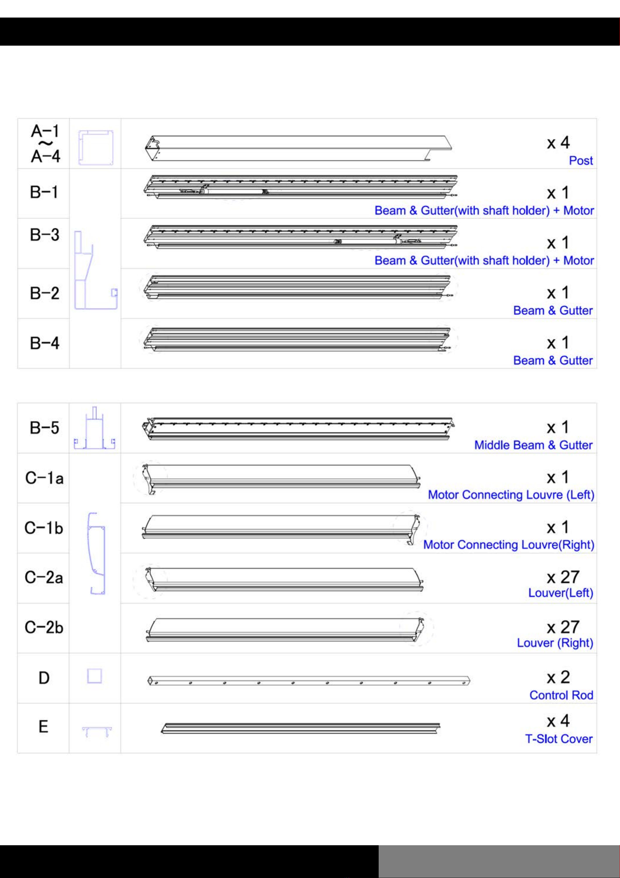
PARTS LIST
Before commencing the installation, please confirm all
parts are present. Email us at [email protected]
if you have any issues.
www.louvrelounge.co.nz | 5
PARTS LIST

www.louvrelounge.co.nz | 6
LAYOUT

SAFETY DISCLAIMER'S
WARNING: For the safety of yourself and others, it is
essential to follow all instructions and obey warnings.
Definitions:
This warning triangle calls attention to hazards that
that can lead to death, severe injuries or which are
important for the functioning of the Pergola.
This symbol identifies important notes.
Safety Disclaimer's
To install this pergola technical knowledge is necessary. Do not
install this pergola yourself instead, contact a professional if:
You are unsure if the pergola can be installed in the chosen spot
for installation.
1.
You do not understand the instruction manual or parts of it.2.
You do not have the necessary tools available.3.
You do not have the necessary technical knowledge4.
A minimum of three healthy adults are required to move and install
the pergola as the product is big and heavy. Do not try to install the
pergola alone. If the pergola falls, it could cause serious injuries and
damages! Contact us or a professional for help.
www.louvrelounge.co.nz | 7

Do not install the pergola when you find damaged parts or parts that
are missing. Contact us.
Keep children and pets out of the working area during assembly and
adjustments.
This product and its fixing parts are only suitable for installation on a
plain flat cement pad. If the concrete pad shows cracks or you
require installation on a wooden deck, please consult a professional
before installation.
Nobody is permitted to change the pergolas’ design and structure
without the permission of us (Louvre Lounge Limited)
Nobody is allowed to climb onto the Pergola. Hanging anything on
the Pergola is forbidden.
The sheeting used to protect the paint must be removed after installation. This
structure is a non-permanent structure, the warranty does not cover damage
incurred under extreme weather conditions including heavy rain, high winds or
if exposed to high heat from heaters or BBQs. Please refer to the warranty
policy for more information.
Safety precautions should always be followed when assembling and using this
product to reduce the risk of personal injury and damage to equipment. Never
leave children unattended around/under this pergola. Do not attempt to
assemble or use the pergola in moderate or heavy wind conditions.
Always secure the pergola and keep the louvres open during heavy winds or
extreme weather to avoid damage to the pergola or personal injury.
www.louvrelounge.co.nz | 8

To ensure the optimal placement of the power plug
that supplies the pergola with electricity, it is
recommended that the following guidelines be taken
into consideration:
The motor will be mounted specifically on beam B-1
and B-3. Consequently, the most suitable location for
the plug would be the posts (A-1 and A-4) which are
nearest to the motor mounting point.
www.louvrelounge.co.nz | 9
PREASSEMBLY TIPS
Wiring Placement
This kit includes base plate covers. While not a
mandatory component, the covers offer a neat
appearance once the pergola has been secured to its
foundation. If blinds are intended to be installed, base
plate covers must be installed.
To install, simply slide a post cover along all four
disassembled posts prior to attaching the base plates.
Post Covers
We recommend sealing all gutters with Silicone
sealant to ensure longevity and maximum water
protection.
Silicone Sealant
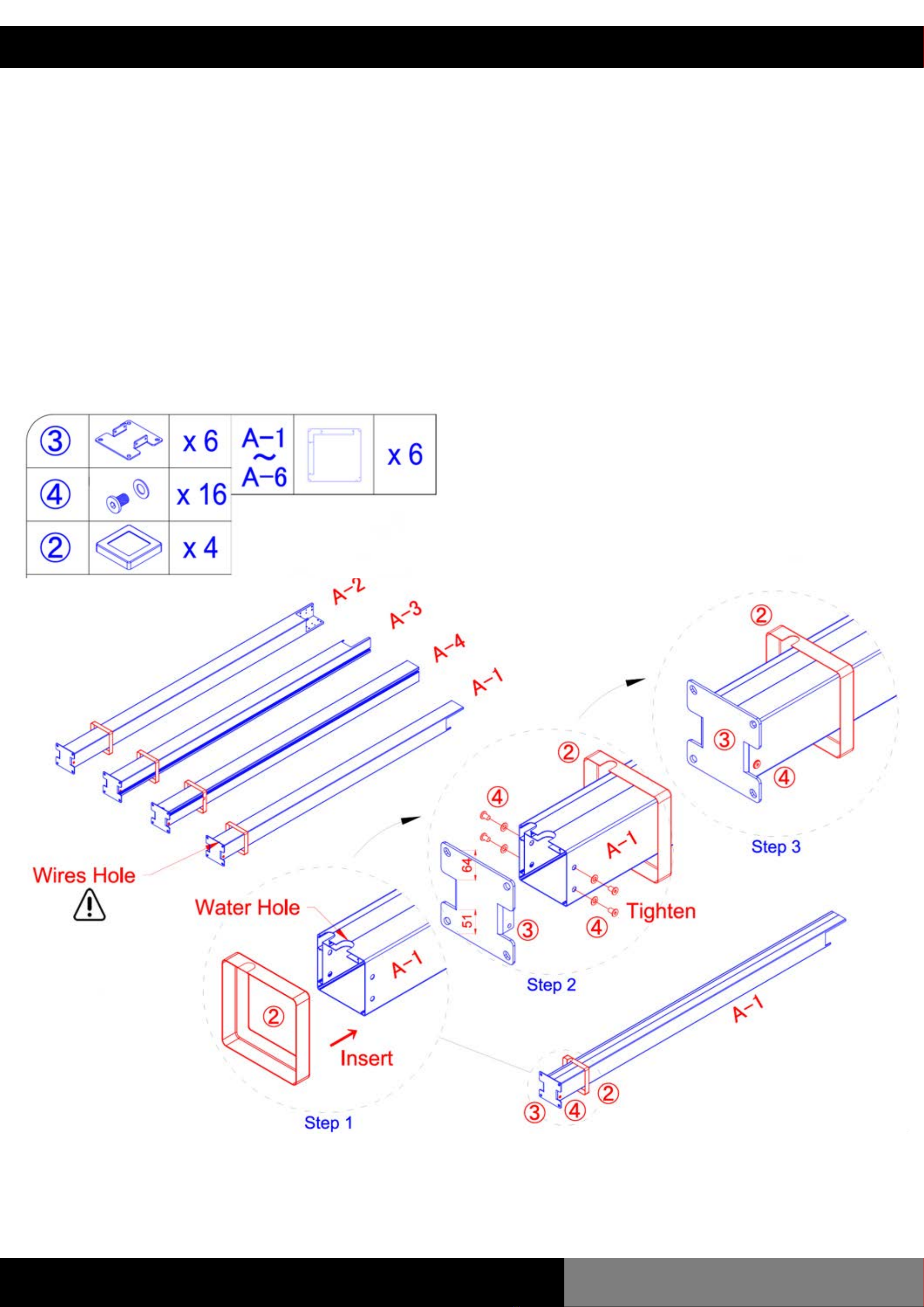
INSTALLATION
Step 1:
a. Insert the all 6 Base Plate Covers (2) on to each post.
b. Align each Base Plate (3) with the x4 holes on each
post. Fix the Base Plates in place with x4 M8*12 Hex
Screws (4) per post.
www.louvrelounge.co.nz | 10
NOTE: Ensure drainage
holes match that of the
diagram.
NOTE: On posts with plugs, thread through base plate
cover before attaching base plate.
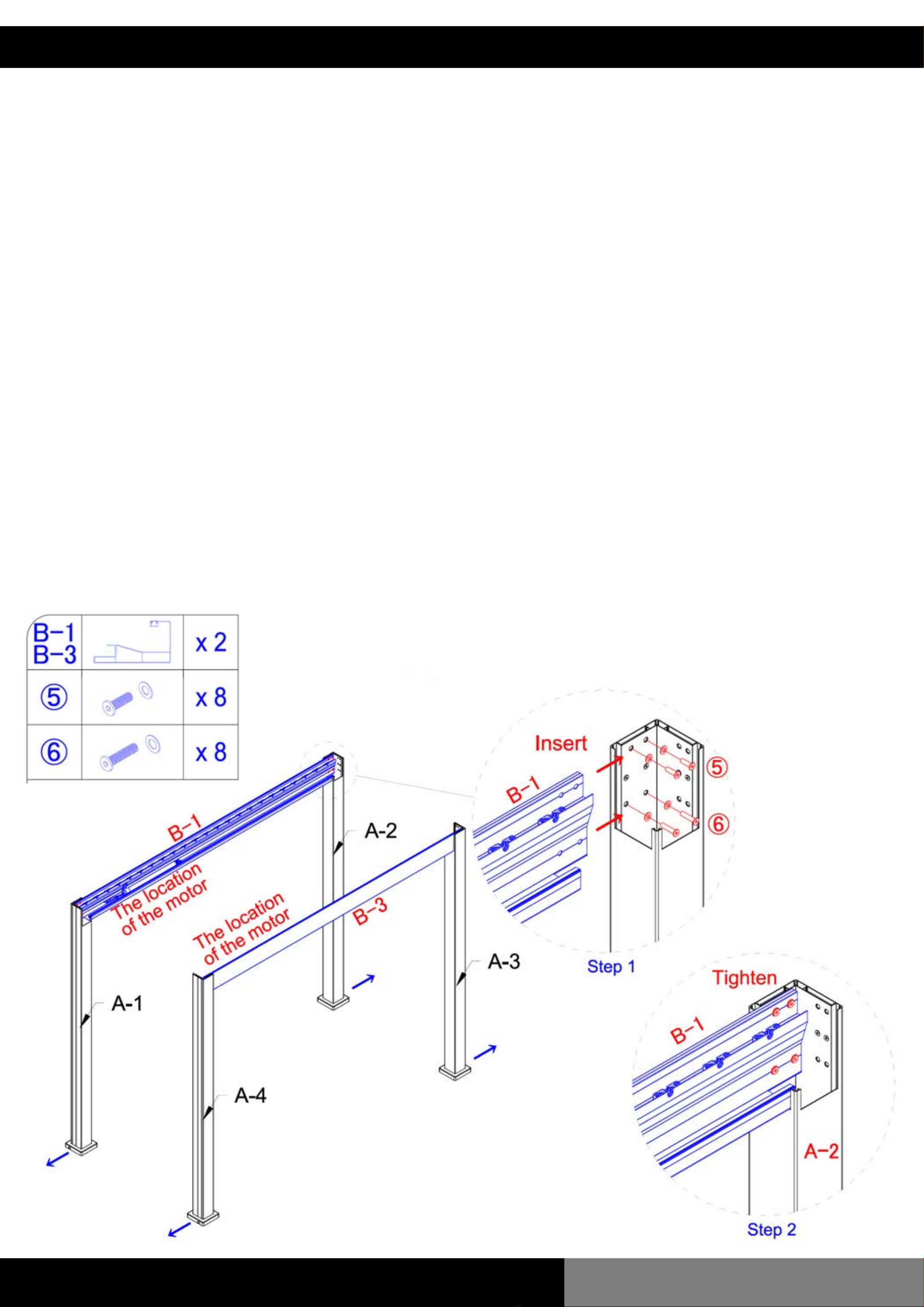
www.louvrelounge.co.nz | 11
Insert the Beam and Gutter (B-1 and B-3) into the posts
as per the diagram below.
Fix the Beam and Gutters to the posts using both M8*25
Hex Screws (5) and M8*35 Hex Screws (6). Tighten to
secure in place.
Note: Hex Screws (5) are screwed in the top two holes
while Hex Screws (6) are screwed in the bottom two
holes of each post.
INSTALLATION
Step 2:

www.louvrelounge.co.nz | 12
Insert the Beam and Gutter (B-2 and B-4) into the
posts.
Fix the Beam and Gutters to the posts as per the
diagram using both M8*25 Hex Screws (5) and M8*35
Hex Screws (6). Tighten to secure in place.
Note: Hex Screws (5) are screwed in the top two holes
while Hex Screws (6) are screwed in the bottom two
holes of each post.
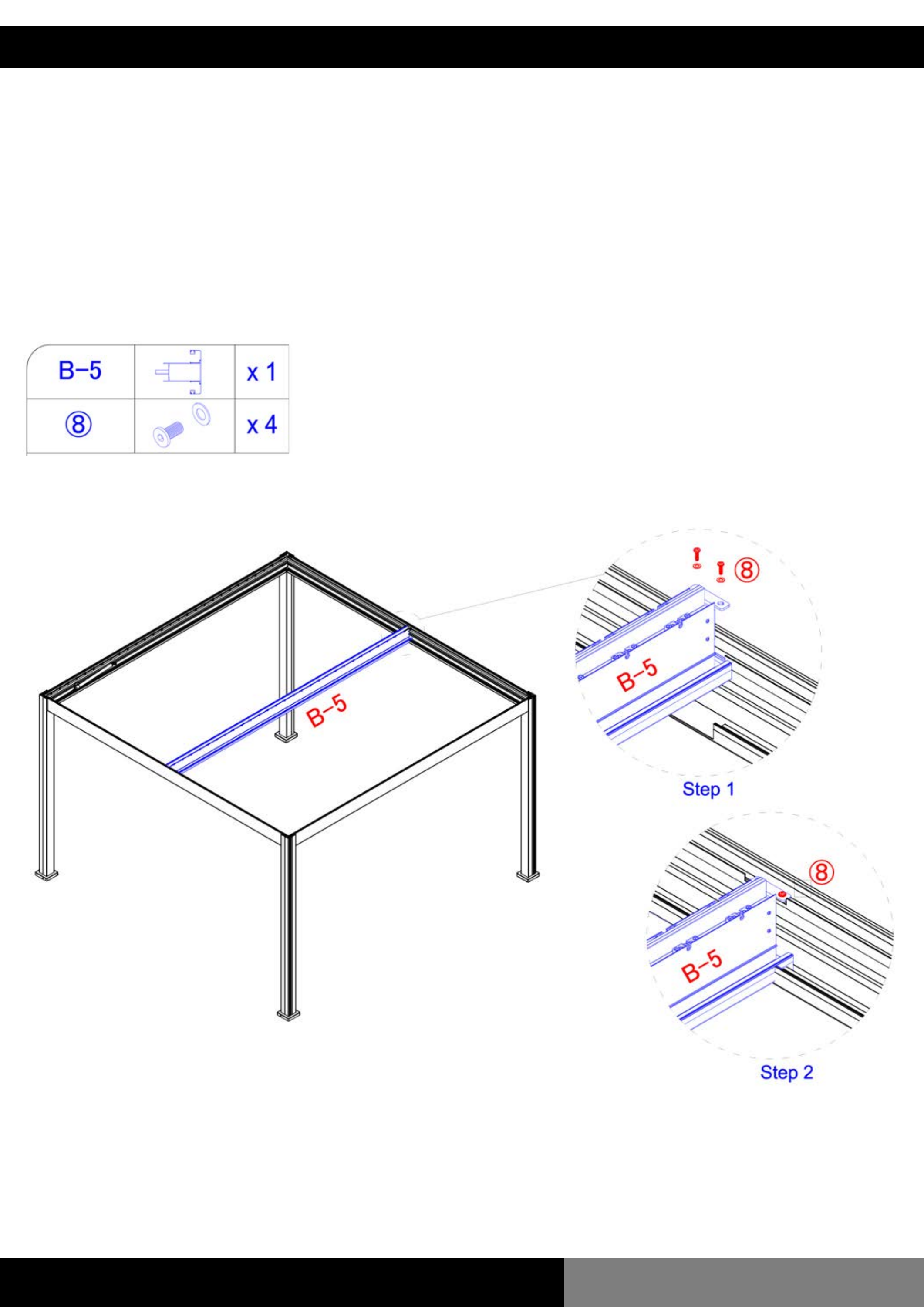
INSTALLATION
Step 3:
www.louvrelounge.co.nz | 13
Fix the Centre Beam and Gutter (B-5) to Beam and
Gutters (B-2 and B-4) using M8*20 Screws (8). Tighten
to secure in place.
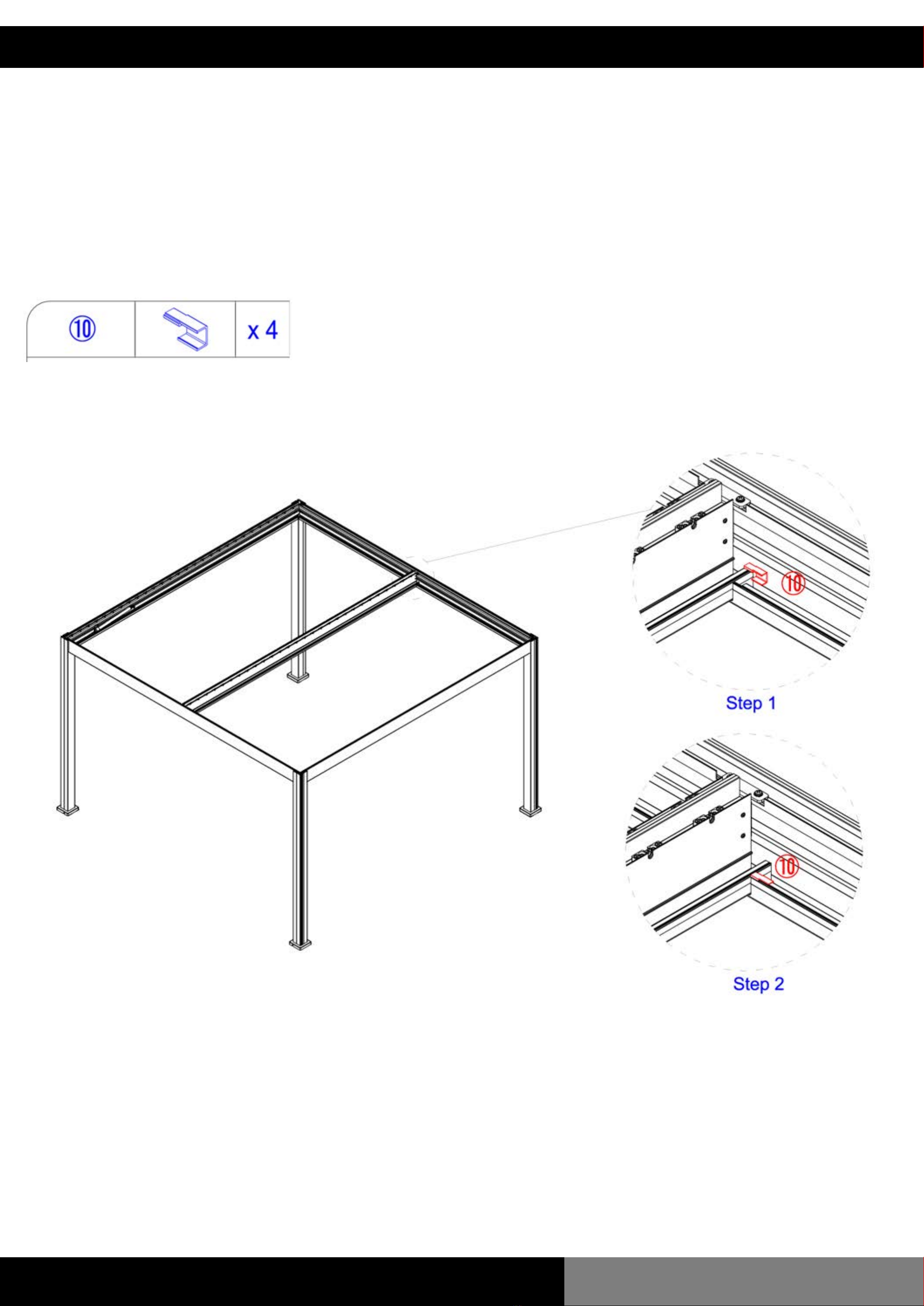
INSTALLATION
Step 4:
www.louvrelounge.co.nz | 14
Slide the Beam Corner Extension Piece (10) into the
side of the beam corner.
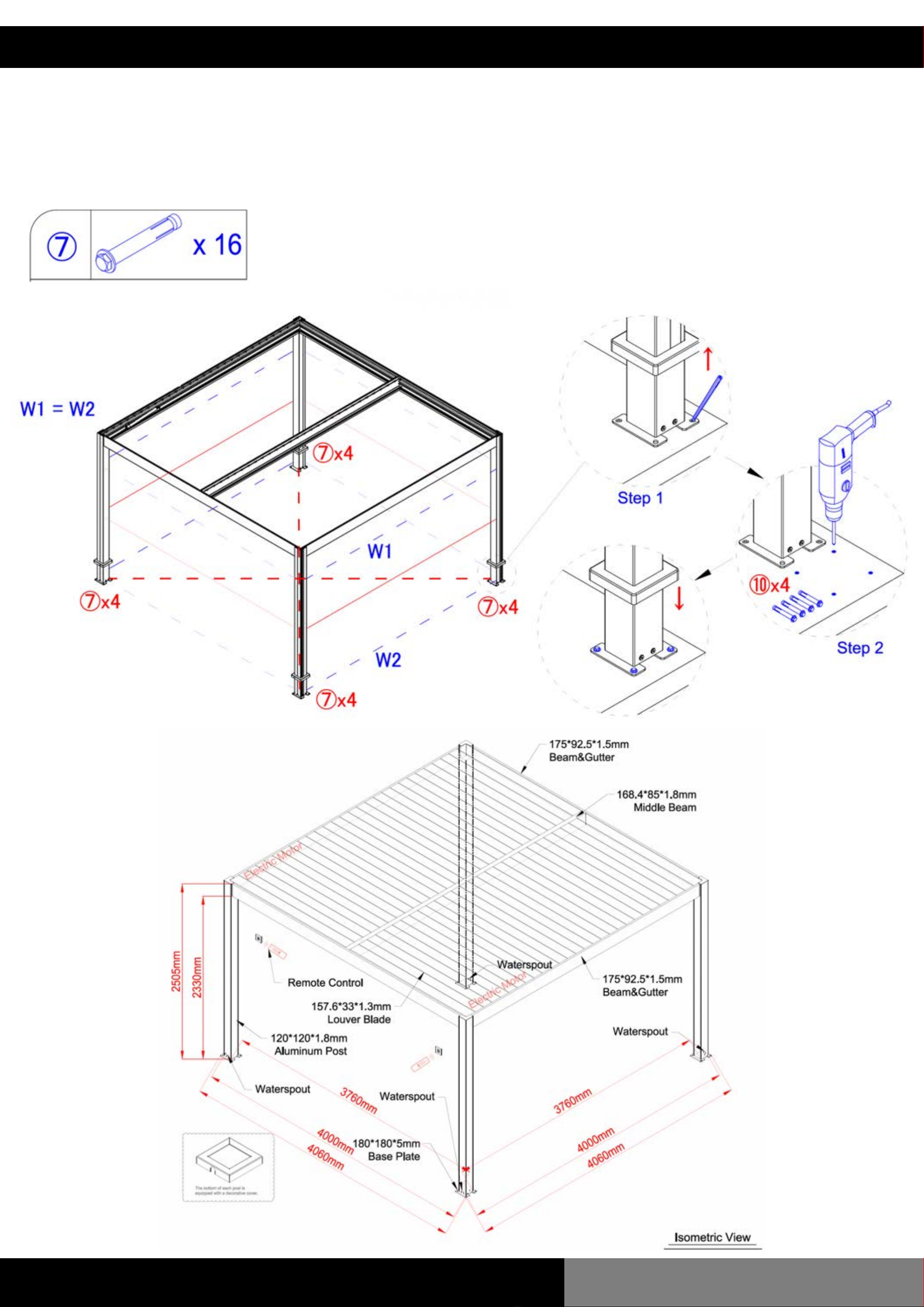
INSTALLATION
Step 5:

www.louvrelounge.co.nz | 15
At this point, we recommend securing the louvre
system to the foundation. We provide instructions to
install into a concrete pad although you must seek
professional advice to ensure the pergola is installed
correctly to all local regulations.
Once the pergola is in place and square, mark 4 holes
for each post then move aside and drill all 16 holes.
Move the pergola back into place and fasten to the
concrete slab by tightening the nuts of the 4 M8*80
Expansion Screws (7) for each post.
Note: Ensure the diagonals of each of the 6 posts are
the same lengths before fixing into place.
For installation into timber decking, please refer to the
diagram on page 26.
INSTALLATION
Step 6:
It is the responsibility of the user to ensure that the louvre system is
fixed down. We (Louvre Lounge Limited) are not responsible for any
damages caused by the louvre system detaching from its foundation.
Any louvre system that is not fixed may be blown away and cause
damage, this responsibility will not be attributed to us (Louvre Lounge
Limited). Check the louvre system regularly to ensure it remains stable
and firmly attached to the ground. Refer to our warranty policy and our
terms and conditions for more information.
www.louvrelounge.co.nz | 16
INSTALLATION
Step 6: (Continued)

www.louvrelounge.co.nz | 17
Connect the LED lighting to the motor power cable by
connecting the male and female plugs (DC24V to
DC24V) between each gutter.
It is essential to make sure the thread nut is tightened
to secure the connection.
DO NOT INSERT THE POWER PLUG INTO AN OUTLET AT
THIS TIME.
Note: Do not place plug near water.
INSTALLATION
Step 7:
Plug voltage: AC220-240V
Light power: 30W

www.louvrelounge.co.nz | 18
a. Slide the Post Corner Extension Piece (9) into place
on the each post corner as per the diagram below.
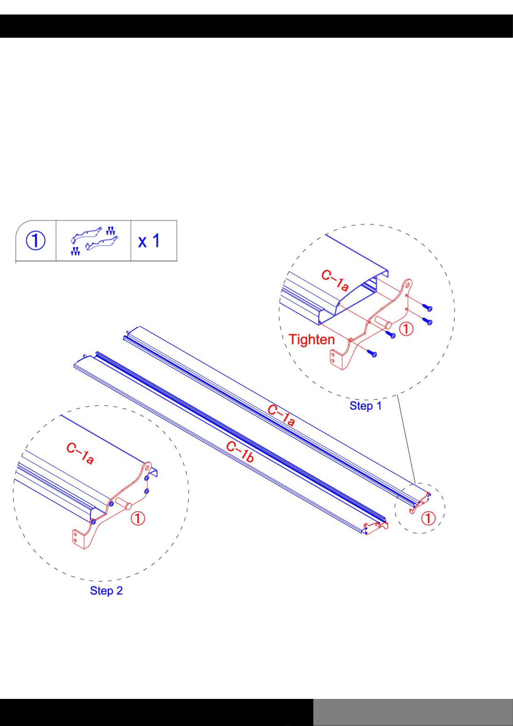
INSTALLATION
Step 8:
www.louvrelounge.co.nz | 19
Fix the Driving Louvre Cover (1) to both driving louvres
(C-1a and C-1b) using x4 4.2*20 Flat Head Screws.
INSTALLATION
Step 9:

www.louvrelounge.co.nz | 20
a. Install each Driving Louvre (C-1a and C-1b) by simply
placing it into the 9th groove of each bay. Ensure the
Driving Louvre Cover installed in the previous step
aligns with the motor arm bracket.
b. Fix the Driving Louvre to the motor arm bracket using
the two screws and bolts already attached to the
motor arm bracket.
Refer to the diagram below.
INSTALLATION
Step 10:
Table of contents
Popular Tent manuals by other brands

Sunstream
Sunstream SWIFTSHIELD A Series ASSEMBLY, INSTALLATION AND USE MANUAL

Rowlinson Garden Products
Rowlinson Garden Products SS229G Assembly instructions

GUIDESMAN
GUIDESMAN 9301718 Assembly instructions

Bell Tent
Bell Tent Standard manual

Vango
Vango WOBURN 400 instructions

Magellan Outdoors
Magellan Outdoors SwiftRise 6P instruction manual


