The t.mix Mix 1832 FX User manual

Owner‘sManual
Mix 1832 Fx
COMpaCt 18-Channel Mixer
Mix 1832 FX
2
www.thomann.de
Important safety notes
Read all safety notes and all instructions. Failure to follow the notes and instructions may result in electric
shock, re or serious injury.
Save this manual for future reference.
DANGER
Electric shock caused by high voltages inside!
Within the unit there are areas where high voltages may be present. To reduce the risk
of electric shock do not remove any covers unless the AC mains power cord is removed.
Covers should be removed by qualied service personnel only.
There are no user-serviceable parts inside.
DANGER
Electric shock caused by short circuit!
Always use proper ready-made insulated mains cabling (power cord) with a protective con-
tact plug. Do not modify the mains cable or the plug. Failure to do so could result in electric
shock/death or re. If in doubt, seek advice from a registered electrician.
DANGER
Electric shock caused by short circuit!
This device has been designed for indoor use only. Do not expose the device to any liquid,
rain or moisture. Do not use the device near water.
Power supply
Notice
Malfunction or damage to equipment!
Ensure that the input voltage (AC outlet) matches the voltage rating of the product. Failure to
do so could result in damage to the product and possibly the user.
Unplug the unit before electrical storms occur and when unused for long periods of time.
Operating conditions
Always install and use the device in accordance with these instructions.
Notice
Malfunction or damage to equipment!
Do not install the unit near any direct heat source. Keep the unit away from naked ames.
Do not block areas of ventilation. Failure to do so could result in re.

Mix 1832 FX
www.thomann.de 3
Contents
Important safety notes ............................................................................................... 2
Introduction ................................................................................................................. 4
Features ....................................................................................................................... 4
Useful information ...................................................................................................... 4
Front side ..................................................................................................................... 5
Quick start ................................................................................................................... 6
Control elements ......................................................................................................... 8
Installation and connection ....................................................................................... 16
Audio connections..................................................................................................... 17
Operation instructions for music player..................................................................... 19
Preset list.................................................................................................................... 20
Technical specifications .............................................................................................. 21
Protecting the environment ....................................................................................... 22
Notes ......................................................................................................................... 23

Mix 1832 FX
4
www.thomann.de
Introduction
Thank you for purchasing the 12-inputs THOMANN Mix 1832 FX compact mixer. Your Mix 1832 FX is a re-
markable compact mixer that doesn‘t nd many equals in the market today, with 6 MIC and 4 Stereo line-level
inputs for serious live performances. Your Mix 1832 FX includes a 24-bit digital multi-effect with 16 factory
presets and 16 variations for every preset, for a total of 256 different digital effects. It has a 3-band sweepable
MID EQ on mono input channels, 4-band EQ on stereo input channels. It also features music player function, it
can connect with the external USB interface, insert the music and WAV le of the music USB disk for playback,
and it supports root directory reading and storing functions. All the above features and its audio quality, make
it perfect for piano bar, karaoke, as well as xed PA installation. Enjoy your Mix 1832 FX and please carefully
read this manual before operation!
Features
6 MIC inputs with gold plated XLR and balanced TRS jack
4 Stereo input channels with balanced TRS jacks
Ultra-low noise discrete MIC preamps with +48 V Phantom Power
SUB1-2, SUB3-4 & MAIN L-R signal assignment switches
4 AUX Sends per channel: 2 PRE/POST faders switchable for monitoring application effects & sound
processor input; 2 POST faders as external send or for internal digital DFX
3-band EQ with sweepable MID on mono inputs; 4-band EQ on stereo inputs
Channel Inserts and Direct Outputs on each mono channel plus Main Inserts for exible connection of
outboard equipment
24-bit internal DSP with 256 effects, 16 presets by 16 variations with DSP Mute switch and Peak LED
2-TRACK IN assignable to Main Mix, Control Room/Headphone outputs
Music player functions
Useful information
Please note important information for future reference:
Serial number:
Date of purchase:
Purchased at:
•
•
•
•
•
•
•
•
•
•
Mix 1832 FX
www.thomann.de 5
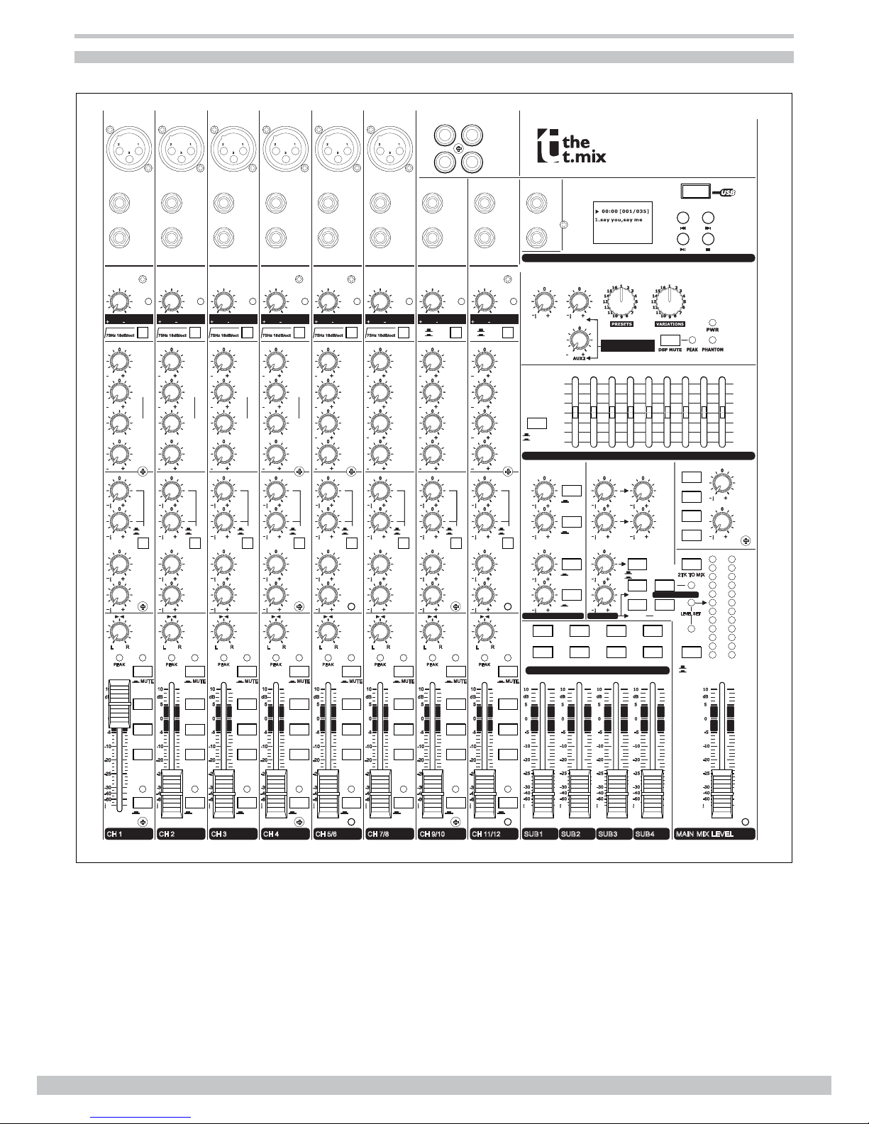
Front side
RIGHT
OUTPUT LEVEL
SOLO MODE
AFL
PFL
TO AUX
TO AUX
MAIN MIX
LEFT LEFT
SUB 3/4
MAIN MIX
R/CTRL
SEND2
-15
STEREO AUX RETURNS
SEND1
0
+15
63 500250125 2K
1K
SOLO ACTIVE
2TK TO MIX
CTRL ROOM
SUB 3-4
2TK IN
-15
MAIN MIX
SUB 1-2 PHONES
CTRL ROOM SOURCE
0
+15
16K
8K
4K
L R
4
SUB 1/2
LEFT LEFT
RIGHT RIGHT RIGHT
AUX SENDS
R-MA N L
¡
10
dB
-5
-10
-20
-25
-30
-40
-60
0
5
¡
10
dB
-5
-10
-20
-25
-30
-40
-60
0
5
¡
10
dB
-5
-10
-20
-25
-30
-40
-60
0
5
¡
10
dB
-5
-10
-20
-25
-30
-40
-60
0
5
¡
10
dB
-5
-10
-20
-25
-30
-40
-60
0
5
DFX2(INT) RETURNS
EFFECTS TO MONITOR
1.warm hall
2.bright hall
3.warm room
4.bright room
5.warm vocal
6.bright vocal
7.plate reverb
8.stereo delay
9.mono delay
10.chorus
11.anger
12.vibrato
13.rev + delay
14.rev + chorus
15.rev + anger
16.rev + vibrate
LEVEL SET
-2
-4
-10
-20
-7
-30
10
CLIP
2
4
7
0
SOLO
SOLO
SOLO
SOLO
EQ OFF
EQ ON
¡
15
EFFECTS OUT AUX1
1
2
¡
15
¡
15
1
2
¡
15
¡
15
1
2
¡
15
¡
15
3
¡
15
¡
15
¡
15
¡
15
4
3
¡
15
¡
15
4-DFX2 SEND
4-DFX2 RETURN
AUX RETURNS SOLO
15 15
LINE
MUSIC
15 15 15 15 15 15 15 15
HI-MID
3kHz
HI-MID
3kHz
HI-MID
3kHz
HI-MID
3kHz
MID-LOW
500Hz
MID-LOW
500Hz
MID-LOW
500Hz
MID-LOW
500Hz
15 15 15 15 15 15 15 15
4
PRE
POST
LEVEL SET
١-٢ UB
٣-٤ UB
R-MA N L
¡
10
dB
-5
-10
-20
-25
-30
-40
-60
0
5
PE A K
MIC 1
LOW
80Hz
EQ
TRIM
HIGH
12KHZ
INSERT
LINE IN 1
BAL
UNBAL
1
LOW CUT
DF X 1
(EXT)
DF X 2
(I N T )
PAN
MUTE
SOLO
MID
FREQ
15 15
100Hz
8KHz
AUX
2
3
RL
CH 1
15 15
15 15
¡
15
¡
15
¡
15
¡
15
50dB0dB LINE
MIC
15dB 35dB
4
PRE
POST
LEVEL SET
١-٢ UB
٣-٤ UB
R-MA N L
¡
10
dB
-5
-10
-20
-25
-30
-40
-60
0
5
PE A K
MIC 2
LOW
80Hz
EQ
TRIM
HIGH
12KHZ
INSERT
LINE IN 2
BAL
UNBAL
1
LOW CUT
DF X 1
(EXT)
DF X 2
(INT)
PAN
MUTE
SOLO
MID
FREQ
15 15
100Hz
8KHz
AUX
2
3
RL
CH 2
15 15
15 15
¡
15
¡
15
¡
15
¡
15
50dB0dB LINE
MIC
15dB 35dB
4
PRE
POST
LEVEL SET
١-٢ UB
٣-٤ UB
R-MA N L
¡
10
dB
-5
-10
-20
-25
-30
-40
-60
0
5
PE A K
MIC 3
LOW
80Hz
EQ
TRIM
HIGH
12KHZ
INSERT
LINE IN 3
BAL
UNBAL
1
LOW CUT
DF X 1
(EXT)
DF X 2
(INT)
PAN
MUTE
SOLO
MID
FREQ
15 15
100Hz
8KHz
AUX
2
3
RL
CH 3
15 15
15 15
¡
15
¡
15
¡
15
¡
15
50dB
0dB LINE
MIC
15dB 35dB
4
PRE
POST
LEVEL SET
١-٢ UB
٣-٤ UB
R-MA N L
¡
10
dB
-5
-10
-20
-25
-30
-40
-60
0
5
PE A K
MIC 4
LOW
80Hz
EQ
TRIM
HIGH
12KHZ
INSERT
LINE IN 4
BAL
UNBAL
1
LOW CUT
DFX1
(EXT)
DF X 2
(INT)
PAN
MUTE
SOLO
MID
FREQ
15 15
100Hz
8KHz
AUX
2
3
R
L
CH 4
15 15
15 15
¡
15
¡
15
¡
15
¡
15
50dB0dB LINE
MIC
15dB 35dB
4 4 4 4
PRE
POST PRE
POST PRE
POST PRE
POST
LEVEL SET LEVEL SET LEVEL SET LEVEL SET
١-٢ UB ١-٢ UB ١-٢ UB ١-٢ UB
٣-٤ UB ٣-٤ UB ٣-٤ UB ٣-٤ UB
R-MA N L R-MA N L R-MA N L R-MA N L
¡¡ ¡ ¡
10 10 10 10
dB dB dBdB
-5 -5 -5 -5
-10 -10 -10 -10
-20 -20 -20 -20
-25 -25 -25 -25
-30 -30 -30 -30
-40 -40 -40 -40
-60 -60 -60 -60
0 0 0 0
5 5 5 5
PE A K PEA K P EAK P E AK
MIC 5 MIC 6
LOW
80Hz
LOW
80Hz
LOW
80Hz
LOW
80Hz
EQ EQ EQ EQ
TRIM TRIM LINE
GAIN
HIGH
12KHZ
HIGH
12KHZ
HIGH
12KHZ
HIGH
12KHZ
RIGHT
LINE IN 5/6 LINE IN 7/8
BAL
UNBAL
1 1 1 1
LOW CUT LOW CUT
DF X 1
(EXT)
DFX1
(EXT)
DFX1
(EXT)
DFX1
(EXT)
DFX2
(INT)
DFX2
(INT)
DF X 2
(INT)
DFX2
(INT)
BAL BAL BAL BA L
MUTE MUTE MUT E MUT E
SOLO SOLO SOLO SOLO
15 15 15 15 15 15 15 15
AUX AUX AUX AU X
2 2 2 2
3 3 3 3
RR R RL L L L
CH 5/6 CH 7/8 CH 9/10 CH 11/12
15 15 15 15 15 15 15 15
¡
15
¡
15
¡
15
¡
15
¡
15
¡
15
¡
15
¡
15
¡
15
¡
15
¡
15
¡
15
¡
15
¡
15
¡
15
¡
15
40dB0dB LINE
MIC
20dB 20dB 40dB0dB LINE
MIC
20dB 20dB LINE
20dB 20dB LINE
20dB 20dB
LEFT
(MONO)
LEFT
(MONO)
BAL
UNBAL
RIGHT
TAPE IN TAPE OUT
L
R
L
R
LINE IN 9/10
LEFT
(MONO)
RIGHT
LINE IN 11/12
LEFT
(MONO)
BAL
UNBAL
RIGHT
PHONES
A
B
LINE
GAIN
LINE
USB
SUBGROUPS ASSIGN TO MAIN MIX
MAIN GRAPHIC EQ
SUB1 SUB2 SUB3 SUB4 MAIN MIX LEVEL
DFX PRESETS
¡
15
BAL
UNBAL
MUSIC PLAYER
1
2
3
12
3
1
2
3
1
2
3
1
2
3
12
3Professional Mixer
MIX 1832 FX
RIGHT
OUTPUT LEVEL
SOLO MODE
AFL
PFL
TO AUX
TO AUX
MAIN MIX
LEFT LEFT
SUB 3/4
MAIN MIX
R/CTRL
SEND2
-15
STEREO AUX RETURNS
SEND1
0
+15
63 500250125 2K
1K
SOLO ACTIVE
2TK TO MIX
CTRL ROOM
SUB 3-4
2TK IN
-15
MAIN MIX
SUB 1-2 PHONES
CTRL ROOM SOURCE
0
+15
16K
8K
4K
L R
4
SUB 1/2
LEFT LEFT
RIGHT RIGHT RIGHT
AUX SENDS
R-MA N L
¡
10
dB
-5
-10
-20
-25
-30
-40
-60
0
5
¡
10
dB
-5
-10
-20
-25
-30
-40
-60
0
5
¡
10
dB
-5
-10
-20
-25
-30
-40
-60
0
5
¡
10
dB
-5
-10
-20
-25
-30
-40
-60
0
5
¡
10
dB
-5
-10
-20
-25
-30
-40
-60
0
5
DFX2(INT) RETURNS
EFFECTS TO MONITOR
1.warm hall
2.bright hall
3.warm room
4.bright room
5.warm vocal
6.bright vocal
7.plate reverb
8.stereo delay
9.mono delay
10.chorus
11.anger
12.vibrato
13.rev + delay
14.rev + chorus
15.rev + anger
16.rev + vibrate
LEVEL SET
-2
-4
-10
-20
-7
-30
10
CLIP
2
4
7
0
SOLO
SOLO
SOLO
SOLO
EQ OFF
EQ ON
¡
15
EFFECTS OUT AUX1
1
2
¡
15
¡
15
1
2
¡
15
¡
15
1
2
¡
15
¡
15
3
¡
15
¡
15
¡
15
¡
15
4
3
¡
15
¡
15
4-DFX2 SEND
4-DFX2 RETURN
AUX RETURNS SOLO
15 15
LINE
MUSIC
15 15 15 15 15 15 15 15
HI-MID
3kHz
HI-MID
3kHz
HI-MID
3kHz
HI-MID
3kHz
MID-LOW
500Hz
MID-LOW
500Hz
MID-LOW
500Hz
MID-LOW
500Hz
15 15 15 15 15 15 15 15
4
PRE
POST
LEVEL SET
١-٢ UB
٣-٤ UB
R-MA N L
¡
10
dB
-5
-10
-20
-25
-30
-40
-60
0
5
PE A K
MIC 1
LOW
80Hz
EQ
TRIM
HIGH
12KHZ
INSERT
LINE IN 1
BAL
UNBAL
1
LOW CUT
DF X 1
(EXT)
DF X 2
(I N T )
PAN
MUTE
SOLO
MID
FREQ
15 15
100Hz
8KHz
AUX
2
3
RL
CH 1
15 15
15 15
¡
15
¡
15
¡
15
¡
15
50dB0dB LINE
MIC
15dB 35dB
4
PRE
POST
LEVEL SET
١-٢ UB
٣-٤ UB
R-MA N L
¡
10
dB
-5
-10
-20
-25
-30
-40
-60
0
5
PE A K
MIC 2
LOW
80Hz
EQ
TRIM
HIGH
12KHZ
INSERT
LINE IN 2
BAL
UNBAL
1
LOW CUT
DF X 1
(EXT)
DF X 2
(INT)
PAN
MUTE
SOLO
MID
FREQ
15 15
100Hz
8KHz
AUX
2
3
RL
CH 2
15 15
15 15
¡
15
¡
15
¡
15
¡
15
50dB0dB LINE
MIC
15dB 35dB
4
PRE
POST
LEVEL SET
١-٢ UB
٣-٤ UB
R-MA N L
¡
10
dB
-5
-10
-20
-25
-30
-40
-60
0
5
PE A K
MIC 3
LOW
80Hz
EQ
TRIM
HIGH
12KHZ
INSERT
LINE IN 3
BAL
UNBAL
1
LOW CUT
DF X 1
(EXT)
DF X 2
(INT)
PAN
MUTE
SOLO
MID
FREQ
15 15
100Hz
8KHz
AUX
2
3
RL
CH 3
15 15
15 15
¡
15
¡
15
¡
15
¡
15
50dB
0dB LINE
MIC
15dB 35dB
4
PRE
POST
LEVEL SET
١-٢ UB
٣-٤ UB
R-MA N L
¡
10
dB
-5
-10
-20
-25
-30
-40
-60
0
5
PE A K
MIC 4
LOW
80Hz
EQ
TRIM
HIGH
12KHZ
INSERT
LINE IN 4
BAL
UNBAL
1
LOW CUT
DFX1
(EXT)
DF X 2
(INT)
PAN
MUTE
SOLO
MID
FREQ
15 15
100Hz
8KHz
AUX
2
3
R
L
CH 4
15 15
15 15
¡
15
¡
15
¡
15
¡
15
50dB0dB LINE
MIC
15dB 35dB
4 4 4 4
PRE
POST PRE
POST PRE
POST PRE
POST
LEVEL SET LEVEL SET LEVEL SET LEVEL SET
١-٢ UB ١-٢ UB ١-٢ UB ١-٢ UB
٣-٤ UB ٣-٤ UB ٣-٤ UB ٣-٤ UB
R-MA N L R-MA N L R-MA N L R-MA N L
¡¡ ¡ ¡
10 10 10 10
dB dB dBdB
-5 -5 -5 -5
-10 -10 -10 -10
-20 -20 -20 -20
-25 -25 -25 -25
-30 -30 -30 -30
-40 -40 -40 -40
-60 -60 -60 -60
0 0 0 0
5 5 5 5
PE A K PEA K P EAK P E AK
MIC 5 MIC 6
LOW
80Hz
LOW
80Hz
LOW
80Hz
LOW
80Hz
EQ EQ EQ EQ
TRIM TRIM LINE
GAIN
HIGH
12KHZ
HIGH
12KHZ
HIGH
12KHZ
HIGH
12KHZ
RIGHT
LINE IN 5/6 LINE IN 7/8
BAL
UNBAL
1 1 1 1
LOW CUT LOW CUT
DF X 1
(EXT)
DFX1
(EXT)
DFX1
(EXT)
DFX1
(EXT)
DFX2
(INT)
DFX2
(INT)
DF X 2
(INT)
DFX2
(INT)
BAL BAL BAL BA L
MUTE MUTE MUT E MUT E
SOLO SOLO SOLO SOLO
15 15 15 15 15 15 15 15
AUX AUX AUX AU X
2 2 2 2
3 3 3 3
RR R RL L L L
CH 5/6 CH 7/8 CH 9/10 CH 11/12
15 15 15 15 15 15 15 15
¡
15
¡
15
¡
15
¡
15
¡
15
¡
15
¡
15
¡
15
¡
15
¡
15
¡
15
¡
15
¡
15
¡
15
¡
15
¡
15
40dB0dB LINE
MIC
20dB 20dB 40dB0dB LINE
MIC
20dB 20dB LINE
20dB 20dB LINE
20dB 20dB
LEFT
(MONO)
LEFT
(MONO)
BAL
UNBAL
RIGHT
TAPE IN TAPE OUT
L
R
L
R
LINE IN 9/10
LEFT
(MONO)
RIGHT
LINE IN 11/12
LEFT
(MONO)
BAL
UNBAL
RIGHT
PHONES
A
B
LINE
GAIN
LINE
USB
SUBGROUPS ASSIGN TO MAIN MIX
MAIN GRAPHIC EQ
SUB1 SUB2 SUB3 SUB4 MAIN MIX LEVEL
DFX PRESETS
¡
15
BAL
UNBAL
MUSIC PLAYER
1
2
3
12
3
1
2
3
1
2
3
1
2
3
12
3Professional Mixer
MIX 1832 FX

Mix 1832 FX
6
www.thomann.de
Quick start
This is the fastest way to get something out from your Mix 1832 FX, if you have a keyboard and a microphone
.
Plug the microphone into Channel 1 MIC IN.
Turn down AUX and LEVEL controls on the input channel.
Put the EQ controls on center position.
Connect 2 active speakers to the rear main out connectors.
Turn on your Mix 1832 FX.
Sing or speak into the microphone with normal volume and adjust the channel LEVEL control of half.
If you like, you can adjust the EQ at this stage.
The LED on the Master LED meter should ash only occasionally, otherwise you will hear distortion.
If this LED is not active and you still hear distortion, please turn down a little the input LEVELControl.
Connect your stereo keyboard into channel 5/6 and repeat the sequence.
Here you are. It is your rst gig with your Mix 1832 FX.
1.
2.
3.
4.
5.
6.
7.
8.
9.
Mix 1832 FX
www.thomann.de 7
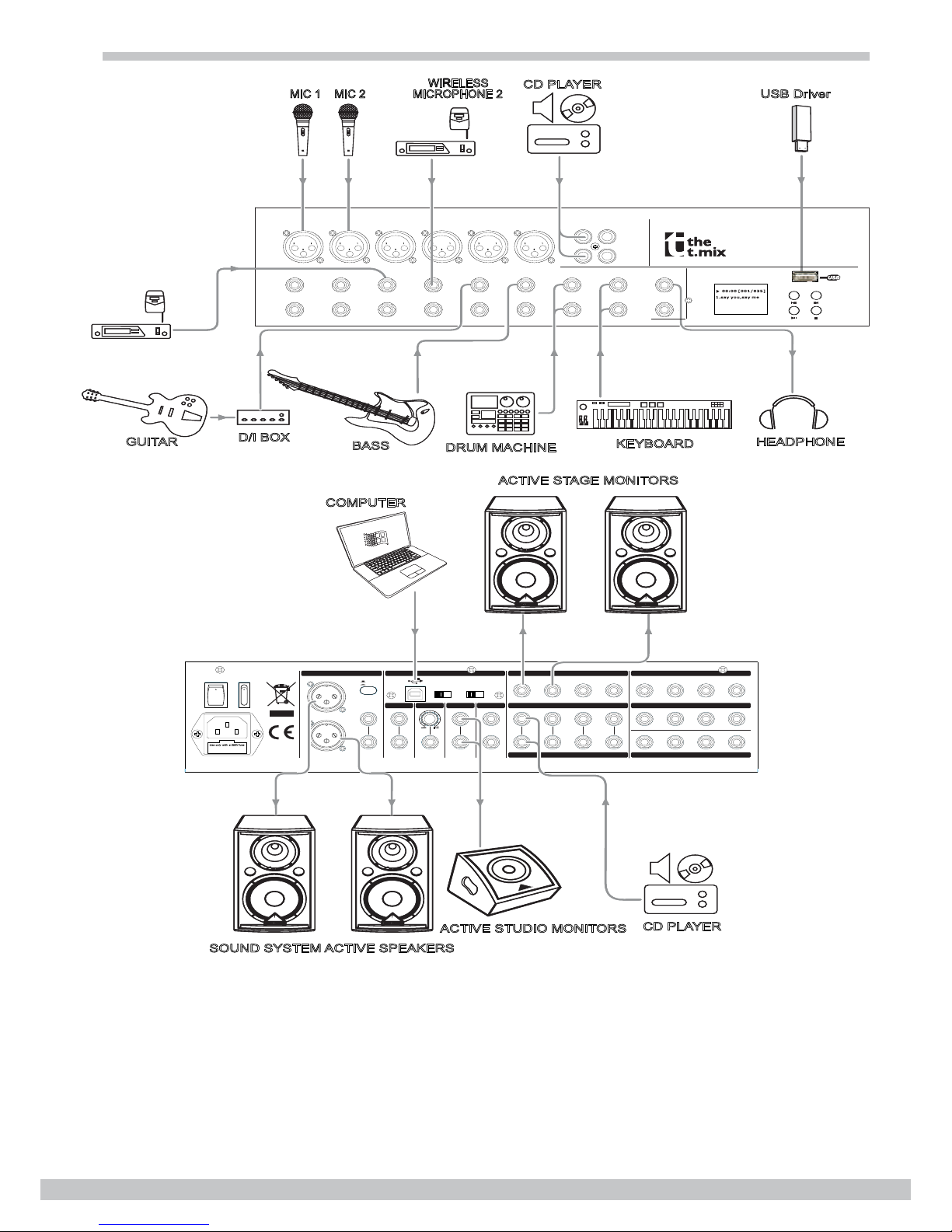
Small gig hookup diagram
Professional Mixer
MIX 1832 FX
RING RETURN FOOT SWITCH
)UNBAL/BAL(
?
L L
?
?
??
?
RR
LL
LL
??
TIP SEND
R R
RR
L
LEVEL
OUTPUT
MAIN
R
PHANTOM
POWER
ON
OFF
??
?
?
+15
-
8
0
+4dBu
-30dBu
RECORD PLAY BACK
SUB
1/2
CH
11/12
MAIN
MIX.
MAIN
MIX.
?CH?CH?CH?CH
??? ?
L
R
CTRL OUT DFX OUTMONO
MAIN INSERT
RATED POWER CONSUMPTION:45W
FUSE: T1.25AH 250V
AC INPUT¡ ¡
100-240V
UNBA /BA (MAIN X OUTPUT( USB AUX SENDS UNBAL/ AL(D CT OUTS(
AUX RETURNS SUBGROUPS OUT
SUBGROUPS INSERT
Use only with a 250V fuse
WIRELESS
MICROPHONE 1
GUITAR D/I BOX BASSKEYBOARD
DRUM MACHINE HEADPHONE
CD PLAYER USB Driver
MIC 1 MIC 2
WIRELESS
MICROPHONE 2
ACTIVE STUDIO MONITORS
ACTIVE STAGE MONITORS
COMPUTER
SOUND SYSTEM ACTIVE SPEAKERS
CD PLAYER
MIC 1
INSERT
LINE IN 1
BAL
UNBAL
MIC 2
INSERT
LINE IN 2
BAL
UNBAL
MIC 3
INSERT
LINE IN 3
BAL
UNBAL
MIC 4
INSERT
LINE IN 4
BAL
UNBAL
MIC 5 MIC 6
RIGHT
LINE IN 5 LINE IN 6
BAL
UNBAL
LEFT
(MONO)
LEFT
(MONO)
BAL
UNBAL
RIGHT
TAPE IN TAPE OUT
L
R
L
R
LINE IN
LEFT
(MONO)
RIGHT
LINE IN
LEFT
(MONO)
BAL
UNBAL
RIGHT
PHONES
A
B
BAL
UNBAL
MUSIC PLAYER
12
3
1
2
3
12
3
12
3
12
3
12
3

Mix 1832 FX
8
www.thomann.de
Control elements
Mono MIC/LINE channels 1
MIC 1
INSERT
LINE IN 1
BAL
UNBAL
1
2
3
1
3
Your Mix 1832 FX is equipped with 4 low-noise microphone preampliers with optional
phantom power, 50 dB of Gain and over 115 dB of S/N ratio. You can connect almost
any type of microphone. Dynamic microphones do not need phantom power. Use
phantom power for condenser microphones only, but make sure that the phantom
power button is disengaged before connecting the microphone. Phantom power will
not damage your dynamic balanced microphones, so make sure to read the MIC in-
structions manual before engaging phantom power. Use switch (48) to activate/deac-
tivate phantom power. These channels are also equipped with ¼-inch TRS balanced/
unbalanced LINE-IN plugs to connect line-level instruments such as keyboards, drum
machines and effect devices.
Mono channel insert 3
This is where you connect external sound processors such as compressor-limiter, equalizers, etc. The insert
point is available on the rst 4 mono MIC channels only.
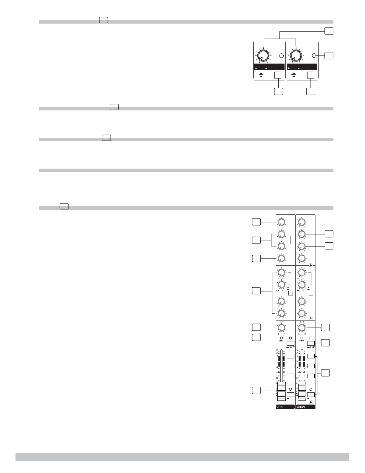
Stereo inputs 2
2
MIC 5
RIGHT
LINE IN 5
BAL
UNBAL
LEFT
(MONO)
1122
33
Die Eingangskanäle 5 bis 12 sind als Stereopaare mit zwei 6,35-mm-Klinkenbuchsen
und XLR-Buchsen ausgeführt. Wenn Sie nur die linke Buchse anschließen, ar-
beitet der Eingang im Mono-Betrieb, d.h., das Mono-Signal, wird auf beiden
Eingangskanälen übertragen. Sie können diese Eingänge mit einem Stereo-
Keyboard, einem Drum-Computer, etc. verwenden.
These are channels 5 through 12. They are organised in stereo pairs and provided
TRIM 4
LEVEL SET
TRIM
LOW CUT
50dB0dB LINE
MIC
15dB 35dB
LEVEL SET
TRIM
LOW CUT
40dB0dB LINE
MIC
20dB 20dB
5
6
7
4
The TRIM control is applied in the mono MIC and stereo input channels. It
provides with 2 different indications: One is for the MIC and the other for LINE
levels. When you use a microphone, you shall read the MIC ring (0 ~ 50) for
mono MIC input, 0 ~ 40 for stereo channels); when you use a line level instrument,
you shall read the LINE ring (+15 ~ -35 dB for mono MIC input, +20 ~ -20 dB for
stereo channels). For optimum operation, you shall set this control in a way
that the PEAK LED (17) blinks only occasionally in order to avoid input channel
distortion.
LINE GAIN 5
When you use a line level instrument, you shall read the ring (-20 ~ +20 dB). For optimum operation, you shall
set this control in a way that the PEAK LED (17) signal peaks only, thus avoiding input channel distortion.
LEVEL SET LED 6
This LED will help you to easily detect the input level, thus making much faster the research of distorted
signals.
Mix 1832 FX
www.thomann.de 9
LOW-CUT button 7
LINE
MUSIC
LEVEL SET LEVEL SET
LINE
GAIN
LINE
20dB 20dB LINE
20dB 20dB
LINE
GAIN
LINE
USB
5
6
89
By pressing this button, you will activate a 75 Hz low frequency lter with
a slope of 18 dB per octave. You can use this facility to reduce the hum
noise infected by the mains power supply, or the stage rumble while using a
microphone.
LINE/MUSIC button 8
By pressing this button, it will switch to the music mode, then the music signal can be sent to this channel or
the main mix channel; by releasing this button, the LINE IN inputs signal will be sent to the line input channels.
LINE/USB button 9
By pressing this button, it will switch to the USB mode, then the USB signal can be sent to this channel or the
main mix channel; by releasing this button, the LINE IN inputs signal will be sent to the line input channels.
Equalizer
There are 3-band EQ with sweepable MID on all mono input channes 1-4: HI, MID and LOW band. There are
4-band xed frequency EQ on the stereo channels 5-12: HI, HI-MID, MID-LOW and LOW band. All bands pro-
vide up to 15 dB of boost or cut.
HIGH 10
4
PRE
POST
LOW
80Hz
EQ
HIGH
12KHZ
1
DFX1
(EXT)
DFX2
(INT)
PAN
MI D
FREQ
15 15
100Hz
8KHz
AUX
2
3
RL
15 15
15 15
∞
15
∞
15
∞
15
∞
15
4
PRE
POST
LOW
80Hz
EQ
HIGH
12KHZ
1
DFX1
(EXT)
DFX2
(INT)
BAL
HI-MID
3k H z
15 15
100Hz
8KHz
AUX
2
3
RL
15 15
15 15
∞
15
∞
15
∞
15
∞
15
SUB 1-2
MAIN L-R
∞
10
dB
-5
-10
-20
-25
-30
-40
-60
0
5
PEA K
MUTE
SOLO
CH 4
∞
10
dB
-5
-10
-20
-25
-30
-40
-60
0
5
PEAK
MUTE
SOLO
CH 5/6
10
11
12
13
14
15
16
17
18
19
20
MID-LOW
500kHz
16
SUB 1-2
SUB 3-4 SUB 3-4
MAIN L-R
If you turn this control up, you will boost all the frequencies above 12 kHz (shelv-
ing lter). You will add transparency to vocals and guitar and also make cymbals
crispier. Turn the control down to cut all frequencies above 12 kHz. In such way,
you can reduce human voice sibilances or reduce a tape player hiss.

Mix 1832 FX
10
www.thomann.de
MID 11
This is a peaking lter and it will boost/cut frequencies from 100 Hz to 8 kHz depending on the position of the
MID freq control. Setting the frequency control on lower frequencies, this control will affect the range of fun-
damental frequencies of most instruments, including human voices, as well as some harmonics when set to
higher frequencies.
HI-MID 12
This control gives you up to 15 dB boost or cut at 3 kHz. It is useful for controlling voice. Making the perform-
ance brighter.
MID-LOW 13
This control gives you up to 15 dB boost or cut at 500 Hz.
LOW 14
Turning this control up, all the frequencies below 80 Hz will be boosted. You will give more punch to bass drum
and bass guitar and make the vocalist more ”macho”. Turning it down, you will cut all the frequencies below
80 Hz. In this way, you can avoid low-frequency vibrations and resonance thus preserving the life of your
woofers.
AUX sends level control 15
These four controls are used to adjust the level of the respective signal sent to the AUX bus. AUX1 and AUX2
can be switched to PRE/POST-FADER via the PRE/POST button, so, generally, they‘re used PRE-FADER
for monitor application and POST-FADER for effect units. AUX3 and AUX4 are congured as POST-Faders.
Generally speaking, the users of this unit will use the onboard DSP effect module setting AUX send 4.
Alternatively, it‘s possible to connect an external effect unit input to EFX2 SEND connector.
PAN/BAL control 16
Abbreviation of PANORAMA control for mono channels, allowing to set the stereo signal front. Keeping
this control in central position, the signal will be equal in both left and right speakers. Stereo channels have
BALANCE control, similar to your hi- set control.
PEAK LED 17
Inside your Mix 1832 FX mixer, the audio signal is treated in several different stages and then sent to the
PEAK LED. When the LED is red illuminated, it warns you that you are reaching signal saturation and possible
distortion. To avoid distortion you should reduce the GAIN, EQ, or LEVEL settings.
MUTE button & LED 18
Each channel is equipped with a MUTE button. Pressing this button is equal to turning the fader down, which
can mute the corresponding channel output except for the channel INSERT send and SOLO (in Pre-Fader-
Liste mode, PFL). And the MUTE LED will illuminate.
ASSIGNMENT controls 19
Each channel provides four push-buttons: SUB1-2, SUB3-4, MAIN L-R and SOLO. Pressing the SOLO button,
the corresponding SOLO LED will illuminate and the SOLO signal will replace other signals send to the head-
phone/control room and meters. Usually use the SOLO function in live work to preview channels before they
are let into the mix. It is useful to set an instrument‘s input level and EQ, and you can also solo any channel
that you want to. The SOLO switch never affects any mix other than the control room. The other three buttons
are signal assignment switches. Pressing the SUB1-2 will assign the channel signal to subgroup 1/2, using
the PAN knob you can adjust the amount of channel signal sent to the SUB1 versus SUB2, completely turning
the PAN to left, the signal will be adressed to subgroup1 only and vice -versa. In the same way, pressing the
SUB3-4 or MAIN L/R will assign the channel signal to subgroup 3/4 or main mix L/R, and this setting too will be
affected by PAN.
FADER 20
This fader will adjust the overall level of this channel and set the amount of signal send to SUB1-2, SUB3-4,
and main L-R outputs.

Mix 1832 FX
www.thomann.de 11
Control Room Source 21
RIGHT
OUTPUT LEVEL
SOLO MODE
AFL
PFL
TO AUX
TO AUX
MAIN MIX
LEFT LEFT
SUB 3/4
MAIN MIX
R/CTRL
SEND2
STEREO AUX RETURNS
SEND1
SOLO ACTIVE
2TK TO MIX
CTRL ROOM
SUB 3-4
2TK IN
MAIN MIX
SUB 1-2 PHONES
CTRL ROOM SOURCE
L R
4
SUB 1/2
LEFT LEFT
RIGHT RIGHT RIGHT
AUX SENDS
∞
10
dB
-5
-1 0
-20
- 25
-30
- 40
- 60
0
5
∞
10
dB
-5
-1 0
-2 0
- 25
-30
-40
-60
0
5
∞
10
dB
- 5
-1 0
-20
- 25
- 30
- 40
- 60
0
5
∞
10
dB
-5
- 10
- 20
- 25
- 30
- 40
- 60
0
5
∞
10
dB
- 5
- 10
- 20
-2 5
-30
- 40
- 60
0
5
LEVEL SET
-2
-4
-10
-20
-7
-30
10
CLIP
2
4
7
0
SOLO
SOLO
SOLO
SOLO
1
2
∞
15
∞
15
1
2
∞
15
∞
15
1
2
∞
15
∞
15
3
∞
15
∞
15
∞
15
∞
15
4
3
∞
15
∞
15
4-DFX2 SEND
4-DFX2 RETURN
AUX RETURNS SOLO
SUBGROUPS ASSIGN TO MAIN MIX
MAIN GRAPHIC EQ
SUB1 SUB2 SUB3 SUB4 MAIN MIX LEVEL
2122
23 24 25
26
27
28
29
30
31 32
33
34
35
You can choose to monitor any combination of MAIN MIX, SUB1-
2, SUB 3-4 and 2TK IN via these Matrix switches. Engaging these
switches, the stereo signals will be delivered to the Phones, Control
Room and Meters display.
NOTE: When any SOLO switch was engaged, the SOLO signal will
replace other signals, and that signal will be present to Control Room,
Phones, and Meters.
PHONES/CTRL room controls 22
Rotate these knobs to independently adjust the stereo level of CTRL ROOM and PHONES. These levels can
be adjusted from –∞to MAX.
Master AUX SENDS controls 23
These four controls are used to determine the master AUX SEND levels, which can be varied from –∞to
+15 dB. Connecting to your mixer an external effect units with no input gain control, you can get a further
+15 dB gain available from these Aux Send outputs. In the same way, the AUX4 master control will provide the
needed level adjustment for the internal effect unit.
SOLO Button 24
The function of these SOLO buttons is similar to channel SOLO buttons. Pressing any SOLO button, the cor-
responding AUX send will be routed to the ctrl room/phones outputs and meters display.
Master STEREO AUX RETURNS controls 1–4 25
These four controls set the level of effects received by stereo AUX RETURN connectors, which can be varied
from –∞ to +15 dB. They are used to provide the further gain for low level effects.
TO AUX SEND 1/2 26
Both these rotary knobs assign the AUX RETURN signals to their respective AUX SEND outputs: The
“TO AUX SEND1” assigns the signal from AUX RETURN1 to AUX SEND1 bus, and “TO AUX SEND2” assigns
the signal from AUX RETURN2 to AUX SEND2 bus. The adjustable range goes from –∞ to +15 dB.
MAIN MIX & CTRL/R button 27
AUX RETURN3 is equipped with the Main Mix & Ctrl/R button. Release the button to send the stereo signal from
AUX RETURN3 to MAIN MIX buses. Engage the button, then the stereo signal will be sent to CTRL/R output.
SUB1-2/SUB3-4/MAIN MIX buttons 28
These three buttons are congured for AUX RETURN4, they can be regarded as the signal assignment switch-
es. When engaging the SUB1-2, the stereo signal from AUX RETURN4 will be assigned to subgroup1/2; in
the same way, pressing SUB3-4 the signal will be assigned to Subgroup3/4, and pressing MAIN MIX it will be
assigned to MAIN MIX buses.
Mix 1832 FX
12
www.thomann.de
AUX RETURNS SOLO button 29
The function of AUX RETURN SOLO is like the channel SOLO button. Engaging this switch signal from AUX
RETURN (1-4) will be sent to CTRL OUT, PHONES outputs and Meters display. Pressing this button, the LED
next to the button will light. This feature is affected by SOLO mode button (n.35).
SUBGROUPS ASSIGN TO MAIN MIX 30
Through these switches, you can operate the subgroup faders as master controls assigning the subgroup
signals to MAIN MIX. Engage the LEFT switch to send the corresponding subgroup signal to MAIN MIX L, and
the RIGHT switch for MAIN MIX R. When engaging both switches, the signal will be sent to L/R of MAIN MIX.
SUBGROUPS fader 31
These faders are used to control the levels of the signal send to the SUBGROUPS OUT, the adjustable range
goes from –∞ to +10 dB. Any channel that is assigned to the subgroups, not muted and not turned down will
be assigned to the SUBGROUPS OUT.
MAIN MIX LEVEL fader 32
This fader sets the amount of signal send either to the main mix output and to the Tape output.
OUTPUT LEVEL LED meter 33
The stereo 12-segment LED meter shows the level of signal sent to ctrl room and phones outputs.
2TK TO MIX button 34
Engaging this switch allows you to combine the 2-track output with the main mix. In other words, it feeds the
2-track In signals into main L/R output.
SOLO MODE button 35
This button provides two modes: up for PFL (pre-fader-listen) mode, down for AFL (after-fader-listen) mode.
After the Level control, otherwise, release the button will output the soloed signal before the level control.
NOTE: The SOLO function will never affect sound output to main recording output, and also can‘t be affected
by channel‘s MUTE switch.
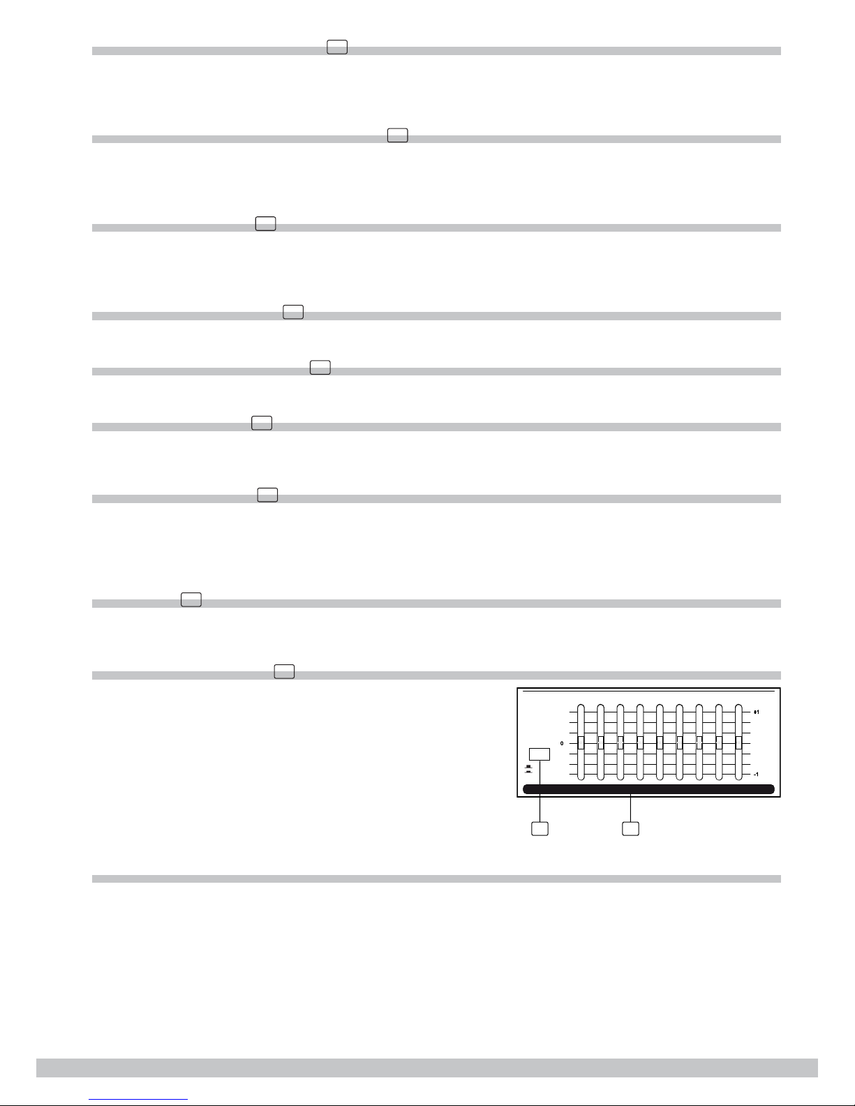
EQ switch 36
Engage this button to include the stereo graphic EQ in ST OUT output circuit. It can be used to modify the
overall sound character of your mix. If you release the button, the stereo graphic EQ will be bypassed.
STEREO GRAPHIC EQ 37
3637
-15
0
+15
63 5002501252K
1K
-15
0
+15
16K
8K4K
EQ OFF
EQ ON
MAIN GRAPHIC EQ
Each one of these faders will boost or attenuate (+/-15 dB) the se-
lected frequency at a preset bandwidth. When all the faders are in
center position, the output of the equalizer is at response.
DSP SECTION
There is a powerful 24-bit/256 preset multi-effects included in your Mix 1832 FX. Effects include reverbs, cho-
rus, anger, delay and combinations of the above.

Mix 1832 FX
www.thomann.de 13
PRESETS 38
38 39
40
41
42
43
44
DFX2(INT) RETURNS
EFFECTS TO MONITOR
∞
15
EFFECTS OUT AUX1
15 15
∞
15
Adjust this knob to select the effect you wish to perform. There are
16 options for you: several kinds of reverb, mono and stereo delay,
effects with modulation, and versatile two-effect combination.
VARIATIONS 39
Once you have selected the desired PRESET effect type, then you can choose among the 16 variations the
one which suits best for performance/song.
DSP MUTE Switch & PEAK LED 40
This switch is used to activate/deactivate the effect facility. This LED lights up when the input signal is too
strong. This LED is lit also when the digital effect module has been muted.
EFFECTS OUT Control 41
Rotate this knob to adjust the level of effect signal generated by the internal digital signal processor and sent
to DFX OUT. The adjustable range is from –∞ to +15 dB.
DFX2 (INT) RETURN EFFECTS TO MONITOR 42
The AUX1 and AUX2 controls are used to set the signal level from AUX RETURN4, whose signal will be sent
to AUX SEND1 and AUX SEND2. The adjustable range is from –∞ to +15 dB.
POWER LED 43
The LED indicates when the power is ON.
PHANTOM LED 44
This LED indicates when the phantom power is switched on.
MUSIC PLAYER
For detailed information refer to section “Operation instructions for music player”.
2-TRACK IN/OUT 45
46
45
MUSIC PLAYER
TAPE IN Use the tape input to listen the playback signal from a tape recorder
or DAT device.
TAPE OUT These RCA jacks will route the main mix signal to a tape
recorder.
PHONES jacks 46
These jacks will be used to send the signal to your headphones.
•
•

Mix 1832 FX
14
www.thomann.de
POWER switch 47
This switch is used to turn the main power on and off.
RING RETURN FOOT SWITCH
)UNBAL/BAL(
4
L L
3
2
41
3
RR
L
LL L
12
TIP SEND
R R
RR
L
LEVEL
OUTPUT
MAIN
R
PHANTOMPOWER
ON
OFF
4
3
2
1
+15
-
8
0
+4dBu
-30dBu
RECORD PLAY BACK
SUB
1/2
CH
11/12
MAIN
MIX.
MAIN
MIX.
CH1
CH2CH3
CH4
4
3
12
L
R
CTRL OUT DFX OUTMONO
MAIN INSERT
RATED POWER CONSUMPTION:45W
FUSE: T1.25AH 250V
100-240V
MAIN MIX OUTPUT (BAL/UNBAL) USB AUX SENDS DIRECT OUTS (BAL/UNBAL)
AUX RETURNS SUBGROUPS OUT
SUBGROUPS INSERT
Use only with a 250V fuseUse only with a 250V fuse
49 50 55
56
57
58
60 62 65 64
63
61
59
51 52 54
53
47 48
AC~ INPUT :
PHANTOM switch 48
It is available only to the XLR MIC sockets. Never plug in a microphone when phantom power is already on.
Before turning phantom power on, make sure that all faders are totally down. In this way, you will protect your
stage monitors and main loudspeakers.
AC inlet with fuse holder 49
Use it to connect your Mix 1832 FX mixer to the main AC with the supplied AC cord. Please check the voltage
available in your country and how the voltage for your Mix 1832 FX mixer is congured before attempting to
connect your Mix 1832 FX mixer to the main AC.
MAIN MIX OUTPUT 50
These stereo outputs are supplied with both the XLR and ¼-inch phone jacks and these outputs are controlled
by the main mix level.
MAIN OUTPUT LEVEL button 51
This button sets the main mix output level to match the input of the device that you are going to connect.
Engage this button to reduce the output level from MAIN MIX OUTPUT by 30 dBu, it is used to match a micro-
phone input @ –30 dBu, or a pro unit input @ +4 dBu.
USB port 52
This USB port is used to connect the unit to a PC in a bi-directional way. The output signal can be choosen be-
tween the SUB1-2 or MAIN MIX output, while the input signal can be addressed to CH11/12 or MAIN MIX input.
USB RECORD switch 53
You can select between SUB1/2 or MAIN MIX the signal to be recorded in your PC.
USB PLAYBACK switch 54
You can select CH11/12 or MAIN MIX track to listen to PC audio signal.
MAIN INSERT 55
These two ¼-inch phone jacks are stereo insert points and used to connect external processors such as com-
pressors, equalisers etc. When inserting an external processor into the jack, the main stereo signal will be sent
out after the EQ and returned into the MAIN MIX output before the MAIN MIX fader.
Mix 1832 FX
www.thomann.de 15
MONO Level control 56
This knob sets the level of mono mix output signal, which can be varied from –∞ to +15 dB.
MONO (BAL/UNBAL) output jack 57
This ¼-inch phone jack is balanced/unbalanced mono mix output connector, it can be regarded as a sum out-
put of the left and right of MAIN MIX.
CTRL OUT jacks 58
These ¼-inch phone jacks will be used to send the control room signal to the studio monitor speakers or a sec-
ond set of PA.
DFX OUT jack 59
This ¼-inch phone jack is used to output the effect signal generated from the internal DSP module. The DSP
output signal level can be controlled by the EFFECTS OUT (41) control.
FOOT SWITCH jack 60
This ¼-inch phone jack can be used to connect an external footswitch to turn on/off the onboard effect module.
AUX SENDS jacks 1–4 61
These ¼-inch phone jacks are used to send out the signal from the AUX bus to external devices such as effect
units and/or stage monitors.
AUX RETURNS jacks 1–4 62
Use these stereo ¼-inch phone jacks to return the stereo signal of an effect unit to the main mix. Alternatively
you can also use them as an extra auxiliary input via using the AUX RETURN level control as volume control.
The signal will be sent directly to main mix control.
DIRECT OUTS jacks 1–4 63
Each mono MIC/LINE channel (CH1-CH4) is equipped with a ¼-inch phone jack for direct output signal. These
jacks are used to send the signal from the channel path to external device for recording function etc.
SUBGROUPS OUT jacks 1–4 64
These ¼-inch phone jacks are used to to record or to connect another sound system, using different levels and
signals from MAIN MIX OUT.
SUBGROUPS INSERT jacks 1–4 65
These ¼-inch TRS phone jacks are insert points. They are congured in a standard way (tip send/ring return)
to be used to connect external processors, such as compressor, limiter, EQ etc. Inserting a “Y” shaped cable
in these jacks, the subgroup signal path will be sent to external unit, then returned before subgroups fader.
Connect the external unit input to “Y” shaped cable tip, and external unit output to “Y” shaped cable ring.

Mix 1832 FX
16
www.thomann.de
Installation and connection
Ok, you have got to this point and you are now in the position to successfully operate your Mix 1832 FX.
However, we advise you to read the following section carefully to be the real master of your own mix. Not
paying enough attention to the input signal level, the routing of the signal and the assignment of the signal
will result in unwanted distortion, a corrupted signal or no sound at all. So you should follow this procedure for
every single channel:
Turn down all input and output gain controls.
Connect phantom powered microphones before switching on the +48 Volt phantom power switch.
Set the output level of your Mix 1832 FX mixer as „0”, and the connected power amplier at no more than
75%.
Now, set the CONTROL ROOM/PHONES level at no more than 50%. In this way, you will be able to hear
later what you are doing connecting a pair of headphones or a pair of powered studio monitor speakers.
Position EQ controls on middle position allowing to set the stereo signal front. Keep this control.
Position panoramic (PAN/BAL) control on center position.
With a pair of headphones or studio monitor speakers connected, apply a line level input signal so that the
PEAK LED does not light up.
Increase the input gain properly for maintaining the good headroom and ideal dynamic range.
Depending on the actual application, turn slowly the input and output level controls for obtaining the
maximum gain before distortion.
Now repeat the same sequence for all input channels. The main LED meter could move up into the red
section. In this case you can adjust the overall output level through the main mix control.
1.
2.
3.
4.
5.
6.
7.
8.
9.
10.

Mix 1832 FX
www.thomann.de 17
Audio connections
You can connect unbalanced equipment to balanced inputs and outputs. Simply follow these schematics.
Y-Stereo lead for insert Connection
2=Hot(+)
3=Cold(-)
1=Ground/Screen
(seen from soldering side)
Use for Balanced Mic Inputs
(For unbalanced use, connect pin 1 to 3)
3-pin XLR Male Plug
2=Hot(+)
3=Cold(-)
1=Ground/Screen
3-pin XLR Line Socket
(seen from soldering side)
1
2
3
1
2
3
Use for Main output
(For unbalanced use, leave pin3 unconnected)
Sleeve=Ground/Screen
Tip=Signal
Sleeve=Ground/Screen
Ring=Return Signal (Connected together)
To Channel Insert
To Tape or FX Input
'Tapped' Connection Direct Output Lead
(Enables the Insert to be used as a Direct Output
while maintaining the channel signal flow)
Sleeve
Sleeve=Ground/Screen
Ring=Return Signal
Tip=Send Signal
To Channel Insert
To Processor Input
To Processor Output
Ring
Tip
(To be used when the processor does not employ a
single jack connection for the In/Out Connections)
USB Connection

Mix 1832 FX
18
www.thomann.de
Operation instructions for music player
Note
USB Memory Format: FAT16, FAT32
Playing type: MP3 only
It can read up to 7 rank folders of your USB ash drive.
Operation Instruction
1. When no USB ash drive is inserted, your Mix 1832 FX display will show the
following screen:
INSERT USB KEY
2. When the the USB ash drive is inserted, the music player starts to search the
music songs in your USB ash drive, and the display shows “Searching”. At the
end of the search, the display will show the following screen. Using “<<” or “>>”
keys, you can select one of following three menu options (“Playing”, “Program”,
and “Folder List”). Pressing “Play”, the unit will enter into the corresponding op-
eration mode.
PLAYING
PROGRAM
FOLDER LIST
MENU:
3. “Playing” mode – single song play
Selecting the “Playing” mode, you will recall the following screen. This screen
displays the name of all the folders containing music les. Using the “<<” or “>>”
keys, you can scan the folders, then press “Play” to open the corresponding
folder. Press “Stop” to return to the main menu.
FOLDER:
POP MUSIC
JAZZ MUSIC
CLASSIC
4. “Program” mode
Select “Program” to enter into the following screen:
“Playlist Set”: Set the playing list
“Playing List”: Play list
Press “<<” or “>>” keys to select, press “Stop” to return to the main menu.
After entering into the “Play List Set”, the display will show the folders con-
taining songs.Selecting the desired folder, the display will show the following
screen. This screen will show all the music les, the selected song will be in-
serted into the playing list and a mark will appear. Pressing again you‘re going
to delete the song from the playing list, and the mark will disappear. Pressing
the “Stop” key, you will return to the main menu. The playing list can accept
up to 20 songs, and it will display the list according to song insert order.
•
•
PLAYLIST SET
PLAYING LIST
The screen will display the following screen. Pressing the “<<” or “>>” keys
you can select the starting song, then pressing the “Play” key the selected
song playback will start. Pressing “Play” again, or pressing “Stop”, the play-
back will stop. Pressing “Play” again, or pressing “Stop”, the playback will start
again from the same point. Twice pressing “Stop” the music player will return
to the main window.
•
CLASSICMUSIC
PLENAPOP03.MP
PLENAPOP02.MP
PLENAPOP
5 Folder List:
The display shows the music les in the current folder or subfolders. Use
“<<” or “>>” keys to navigate. Press „Play“ to play a song or to enter into the
corresponding subfolder. Press “Stop” to return to the main menu.
•
03.PLENAPOP04.MP
03.PLENAPOP06.MP
LENAPOP02.
01.
[ . ] 00 :20
1.
2.
3.

Mix 1832 FX
www.thomann.de 19
Preset list
No. Preset Description Controllable
Parameter
Parameter
Variable range
1WARM HALL Simulates a small acoustic space of the sound. Decay time
Pre-delay
1.0 ~ 2.9s
20 ~ 45ms
2BRIGHT HALL Simulates a large acoustic space of the sound. Decay time
Pre-delay
3.6 ~ 5.4s
23 ~ 55ms
3 WARM ROOM Simulates a bright studio room Decay time
Pre-delay
0.7 ~ 2.1s
20 ~ 45ms
4 BRIGHT ROOM Simulates a studio room with many early reections. Decay time
Pre-delay
2.9 ~ 4.5s
23 ~ 55ms
5 WARM VOCAL Simulates a room with small delay time Decay time
Pre-delay
0.8 ~ 1.1s
0 ~ 79ms
6 BRIGHT VOCAL Simulates a small space with slight decay time Decay time
Pre-delay
0.8 ~ 2.5s
0 ~ 79ms
7PLATE REVERB Simulates the transducers sound like classic bright vocal plate Decay time
Pre-delay
0.6 ~ 6.1s
10ms
8STEREO DELAY Recreates the input sound on the stereo output with different
time
Period
Feedback
210 ~ 400ms
37 ~ 73%
9MONO DELAY Reproduces the sound input on the after a lapse of time Period 60 ~ 650ms
10 CHORUS Recreates the illusion of more than one instrument from a
single instrument sound Rate 0.5 ~ 5Hz
11 FLANGER Simulates to play with another person carrying out same the
notes on the same instrument Rate 0.16 ~ 2.79Hz
12 VIBRATO Vibrato delay with the analog transducers‘ springs lightly
stretched sound
Decay time
Pre-delay
1.3 ~ 5.4s
0 ~ 35ms
13 REV + DELAY Delay with room effect Decay period
Rev.decay time
211 ~ 375ms
1.0 ~ 2.9ms
14 REV + CHORUS Stereo chorus and large room reverb Decay period
Rev.decay time
0.5 ~ 4.74Hz
1.5 ~ 2.9s
15 REV + FLANGER Stereo anger and large room reverb Flanger Rate
Rev.decay time
0.16 ~ 5.52Hz
1.5 ~ 2.9s
16 REV + VIBRATE Simulates a record head and multiple playback heads at
intervals along the tape
Decay time
Pre-delay
1.3 ~ 5.4s
0 ~ 84ms

Mix 1832 FX
20
www.thomann.de
Technical specifications
Input channels Mono channels
Microphone input Electronically balanced, discrete input conguration
Frequency response 10 Hz to 55 kHz, ± 3 dB
Distortion (THD+N) 0.005% at +4 dBu, 1 kHz
Gain range 0 dB to 50 dB (MIC)
SNR (signal to noise ratio) 115 dB
Line input Electronically balanced
Frequency response 10 Hz to 55 kHz, ± 3 dB
Distortion (THD+N) 0.005% at +4 dBu, 1 kHz
Sensitivity Range +15 dBu to –35 dBu
Stereo channels
Line input Balanced/unbalanced
Frequency response 10 Hz to 55 kHz, ± 3 dB
Distortion (THD+N) 0.005% at +4 dBu, 1 kHz
Impedance Microphone input 1.4 kΩ
Channel insert return 2.5 kΩ
All other inputs 10 Ω or greater
Tape out 1 kΩ
All other outputs 120 kΩ
Equalization Hi-shelving ± 15 dB @ 12 kHz
Mid bell (mono) ± 15 dB, frequency range 100 Hz to 8 kHz
Hi-Mid (stereo) ± 15 dB @ 3 kHz
Mid-Low (stereo) ± 15 dB @ 500 Hz
Low-shelving ± 15 dB @ 80 Hz
Low cut lter 75 Hz, 18 dB/Oct.
DSP section A/D and D/A converters 24 bit
DSP resolution 24 bit
Type of effects HALL, ROOM, VOCAL & PLATE REVERB, MONO & STEREO DELAY
(MAX DELAY TIME 650 MS), CHORUS, FLANGER & REVERB MODULATIONS,
REVERB+DELAY, REVERB+CHORUS, REVERB+FLANGER COMBINATIONS
Presets 256
Controls 16-position PRESET/VARIATION selector
DSP MUTE SWITCH with PEAK LED indicator
MUTE switch with LED indicator
Main mix section Noise (bus noise) Fader 0 dB, channels muted: –100 dBr (ref.: +4 dBu)
Fader 0 dB, all input channels assigned and set to
unity gain: –90 dBr (ref.: +4 dBu)
Max output +22 dBu balanced XLR; +22 dBu unbalanced, ¼-inch jacks
AUX returns gain range –∞ to +15 dB
AUX sends max out +22 dBu
Power Supply Main voltage 100 to 240 VAC, 50/60 Hz
Power consumption 40 W
Fuse T1.25 A, 250 VL
Main Connection Standard IEC receptacle
Physical Dimension (W × D × H) 415 mm × 400 mm × 35/115 mm (16.3 in × 15.8 in × 1.49/4.53 in)
Net weight 6.7 kg (14.8 lbs)
Table of contents
Other The t.mix Music Mixer manuals


