AVE Andante 8 User manual

User guide Andante 8 October 2019
Audio Vertriebs
Entwicklungsgesellschaft
mbH
Andante 8
Digital Mixer
with 8 mic/line inputs and 4 outputs
User Guide

User guide Andante 8 page 2
Table of contents
Introduction....................................................................................................................................3
Safety instructions .........................................................................................................................3
Scope of delivery ...........................................................................................................................3
Section 1 (user)
Operation of the Andante 8 in user mode......................................................................................4
Section 2 (qualified personnel)
Installing the software....................................................................................................................5
Programming the Andante 8..........................................................................................................6
Detailed description of automatic mixer and anti-feedback.........................................................16
Section 3 (Admin)
Operation of the Andante 8 in admin mode.................................................................................21
Technical Specifications..............................................................................................................23
Notice...........................................................................................................................................26

User guide Andante 8 page 3
Introduction
Thank you for choosing the 16-channel digital mixer “Andante 8” from AVE.
No matter what your requirements are, due to its advanced technical design, it ensures trouble-free use with
sound exposure in a variety of facilities such as churches, courtrooms, government offices, conference
rooms, schools, universities, etc.
The following information relates to Andante 8. It is also applicable for Andante 8 because only the
number of inputs and outputs are different.
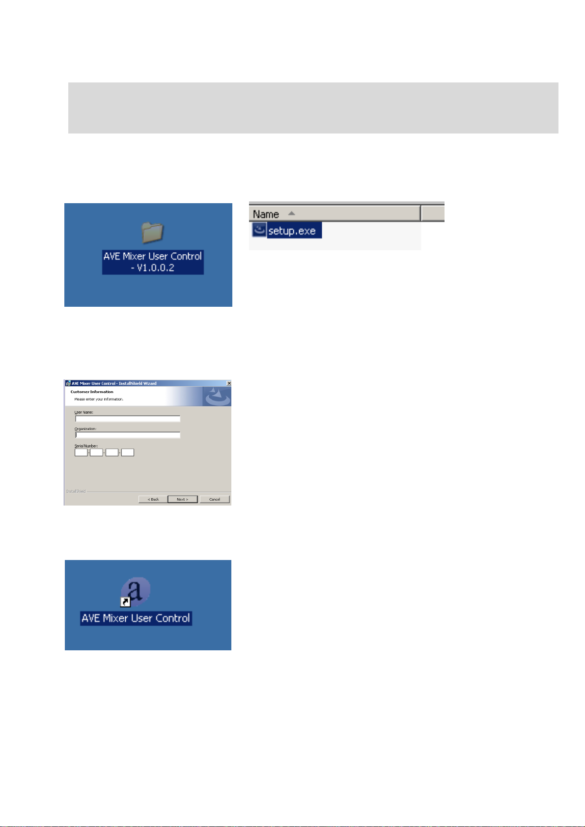
The Andante 8 is equipped with its own software. This makes the programming via laptop or PC easily and
conveniently.
Safety instructions
Located inside the unit are hazardous voltages. Do not remove the cover. Internal modifications or
service work should only be conducted by qualified service personnel.
The Andante 8 is supplied with a proper power supply cable. At one end of this cable is a three-pronged AC
power connector (IEC plug) and at the other end of a CE-standard-compliant Schuko-plug for connection to
a 230 V / 50 Hz AC voltage source. Please ensure that this power supply cable is not damaged. Do not use
defective or damaged power cables!
Scope of delivery
Please check immediately upon receipt the package integrity, the contents for completeness and proper
delivery of the unit.
The delivery scope of the unit includes:
- The “Andante 8”
- USB - cable
- Power supply cable
Please keep the operating instructions in a safe place and make them available to qualified personnel for
making necessary changes to the device.

User guide Andante 8 page 4
This user guide is divided into 3 sections:
Section 1
The first section explains how the user can easily and comfortably change the overall volume and retrieve the
presets (up to 20) directly on the “Andante 16” device without using the laptop or PC.
The volume control in "user mode" is restricted in order to prevent operating errors. If the protection is activated,
the volume is adjusted by pressing and turning the v/v button and to select a preset by pressing and turning the
p/p button.
Control of the entire volume
By turning the v/v button the total volume will be increased or decreased (master volume).
Select preset
With the p/p button a desired preset is selected.
Input level 1-8
Press the select (Sel) button and turn v/v key, to increase or to decrease the volume.
Output level 1-4
Press the select (Sel) button and turn v/v key, to increase or to decrease the volume.
Press the v/v button to return to the main menu.
Power socket RSC 232 Aux Out Outputs 1-4 CD / Aux Input Inputs 1 –8
8 inputs
Each input has the same
functions
Matrix
LED Display:
Input, Clip, Signal, Select
Select button
LED display Select
Matrix Select buttons for assigning
inputs to the outputs
4 outputs
Each input has the same
functions
LED Display:
Output, Clip, Signal, Select
Select button
Display
Volume/Value
Power
switch
Preset/Parameter USB connection

User guide Andante 8 page 5
Section 2
The second section is intended for qualified personnel, which adjusts the settings via PC or laptop and the
programming of the parameters, the automatic, the matrix and the delays, etc. The following modifications
must to be carried out by qualified personnel.
Installing the software
Start the installation program by clicking on the appearing
desktop folder and then clicking on setup.exe.
Then follow the installation instructions.
Enter your user name, your organization name and the license
number that was included.
After installation is complete you will have the following
shortcut on the desktop

User guide Andante 8 page 6
Programming of the Andante 8
Restart your PC or your laptop, so the program can be executed properly. Use the supplied connector cable
between your laptop and Andante 16. Start the program and click with the left mouse bottom on File
and then on New Project.
Specify the type of device and confirm by pressing OK.
This window shows all the functions of the mixer. With the
zoom on the bottom right you can adjust all commands on the
monitor
Click with the left mouse button on Setup and then on Remote
Connection, confirm with OK. After a short time.the display
shows Remote Connected.
Now you can use all the functions you want to program.

User guide Andante 8 page 7
If you use a DHPC router connection make sure that the IP
number of the router is correct. For this purpose press the
preset bottom twice. Then turn the knob until the IP number
appears. Press with the left mouse bottom Setup and then
Remote Connection afterwards Remote Server. Enter the IP
adress and confirm with OK. On the display appears Remote
Connected.
When you click File in the menu bar, a pull-down menu with following
selection options is opened:
New Project A new project is created
Open Project An existig project is opened
Save Projekt The project is saved
Save Project As The project can be saved under a different name
Close Project The project will be closed
Recent Projects Saved projects can be considered
When you click Tools in the menu bar, a pull-down menu with following
selection options is opened:
Operation Mode Choice between Online and Offline
Preset Store Storing presets
Preset Retrieve Retrieve presets
Preset Copy Copying of presets
Other Functions Store Without Sending
allows corrections during a live transmission
without switching in mute mode.

User guide Andante 8 page 8
When you click Windows you can select between Layout control, Preset Manager and System Manager.
Der Preset Manager
Before you save a configuration you have
to give the preset a name to retrieve it
again via Preset Retrieve.
Der System Manager
Start-Up Preset
Choice of the start preset
Main VU-Meter
Choice of the VU meters
Knobs Protection
By pressing and turning the volume control you can
adjust the volume on the device.
PIN Protection
Activation of the PIN of the Admin Mode
PIN Code
Enter of an own PIN Code (Admin Mode)
System Reset

User guide Andante 8 page 9
Layout Control
Peak meters (Input)
Clipping indicator
Peak level indicator
Input On/Out
Input on/out
Phantom power
Analog Gain [dB]
Parametric Equalizer
(Input)
Hum filter 160 Hz
Lowpass/highpass filter
8 band parametric equalizer
8 parameters are available for each input and each output. The settings can be copied to each other input and
output. The same applies to the highpass/lowpass filters.
.
Band Selection
Frequency [Hz)
Gain [dB]
Bandwidth [Oct]
Equalizer Copy

User guide Andante 8 page 10
Noise Gates (Input)
Noise Gate On/Out
Threshold [dB]
Hold time [ms]
Compressor (Input)
On/Out
Threshold [dB]
Ratio
Post Gain [dB]
Attack time [ms]
Release time [ms]
Faders (Input)
Level Setting
Input option for programmer
to change the volume at the input

User guide Andante 8 page 11
Automixer (Eingang)
Select
Automixer on/out
Hold time [ms]
Attenuation [dB]
NOM Gain on/out
Reducing the level when microphones
are activated simultaneously
Priority
Detailed description of the automixer on page 16
Matrix
Matrix on/out
Level Setting [dB]
After pressing the right mouse
bottom a pull-down menu opens.
It allows the activation of all
matrix nodes or different rows or
columns of nodes.
Routing of all inputs and outputs
with additional level setting.
.

User guide Andante 8 page 12
Level setting
Input option for
programmer
to change the volume
at the output.
Level (Output)
Delay (Output)
Delay [m]
Phase
Equalizer (Output)
Parametric EQ
GraphicEQ
Lowpass-/Highpass filter

User guide Andante 8 page 13
Each output has a 31 band graphic
equalizer.
All parameters can be copied to the
other EQs or individually
adjusted for each output.

User guide Andante 8 page 14
Anti-Feedbacks (Outputs)
Detailed description of the
antifeedback functions on page 16
Noise Gates
(Output)
On/Off
Threshold [dB]
Hold time [ms]

User guide Andante 8 page 15
Compressor
(Output)
On/Off
Schwelle [dB]
Ratio
Post Gain [dB]
Attack time [ms]
Release time [ms]
Limiter
(Output)
Limiter On/Off
Output On/Off
Output On/Off

User guide Andante 8 page 16
Peakmeter (Output)
Clipping
Peak Level
Overview adaptive automixer
Automixer processing is useful in situations where multiple microphones are used, such as in churches, board
rooms, conference rooms or courtrooms. Automixer solves the typical problems that occur when multiple mics are
used.
In fact, the voice signal picked up by multiple microphones suffers from multi-path interference, also called comb
filtering. This multi-path interference affects the quality of the sound source by emphasizing sound at some
frequencies and canceling the sound at others
Moreover, multiple opened microphones could easily create multiple potential feedback loops and consequently
input gain must be limited.
Automixer is a real-time sound algorithm that automatically reduces the level of a microphone's audio signal when
it is not being used and maintain a steady limit on the overall signal level of the opened microphones.
Automixer has the following benefits:
Lowering hiss, rumble, reverberation and other extraneous noise that occur when several microphones operate
simultaneously.
Improving gain before feedback.
Reducing the comb-filtering effect.
Automixer is ideally suited for applications such as churches, board rooms, conference rooms or courtrooms.

User guide Andante 8 page 17
Gating
The automixer unit controls the microphone’s state as following:
If the RMS level is above the current adaptive threshold, the microphone’s state is open i.e. the block applies no
attenuation to the signal.
If the RMS level is below the current adaptive threshold, the microphone’s state is attenuated i.e. the block
applies an off attenuation to the signal.
Adaptive Threshold
The internal algorithm dynamically sets the gate threshold level in accordance with the ambient noise. For
example, in a noisy room the automixer would increase the threshold level to prevent any of the microphone
channels from being triggered on by the noise. On the other hand, in a quiet environment, the threshold level
must be lowered.
Last Microphone Hold
Die Funktion „Last Microphone Hold“ lässt das zuletzt aktivierte Mikrofon offen,
auch wenn der Schallpegel unter den eingestellten Schwellenwert fällt.
Selecting
This LED is on when the microphone channel is gated on.
For those input channels with automixer mode disabled, this LED is always off.
Insert I/O
Turns on/off channel gating. When disabled, the microphone state for this
channel remains bypassed (no automixer mode) at all times and its level
does not contribute to adaptive threshold computing or NOM attenuation.
Hold Time
Sets the minimum time an microphone stays open after the user stops talking
(i.e. RMS input level drops below the adaptive threshold level).
Use this control to prevent the gate from opening and closing due to
momentary pauses in speech.
Typical values are comprised between 1 second and 2 seconds.
Attenuation
The off attenuation parameter allows attenuation of inactive inputs from 0 dB to -60 dB.
When hold time is elapsed, the off attenuation is smoothly inserted.
Practical experience has shown that a 15 dB –20 dB attenuation is a good compromise.
NOM GAIN
When NOM GAIN is active for a channel, the automixer will reduce
the gain for the given channel by 3 dB
for every doubling of open channels (-10log(NOM) rule).
The NOM GAIN, if enabled,
is singularly applied on each channel.
Priority
has relevance to assign preference on opening channels.
Compatibly with the actual number of open microphones, the channels with higher priority
will be opened before of the lowest ones.
It does not mean strictly that microphones with higher priority can override ones with lower priority.
Generally, each time two or more channels must be opened, priority level is used to give a precedence order.
Priority increases from 1 (lowest) to 5 (highest).
A special case of priority behavior regards the highest priority that serve to disable all other channels.
With PRIORITY equal to 5, use the additional parameter RESET TIME to determines how long to wait for channel restoring.
Typical values of RESET TIME are between 1 second and 5 seconds.
Application example:
The highest priority reveals useful inside churches during organ playing, where a separate
microphone with PRIORITY equal to 5, placed close to the organ pipes, gates off all
microphones in presbyter.
NOTE:
When you set up your mixing system, make sure you get the right gain on the analog input
gain control. Automixer works better when the gain has been properly set to give the
algorithm adequate signal.
For automixer proper working, best microphone level range is between -40 dB and -10 dB on Peak Level Meter.
NOM
NOM GAIN
1
0 dB
2
-3 dB
3
-3 dB
4
-6 dB
5
-6 dB
6
-6 dB

User guide Andante 8 page 18
Overview Antifeedback
Audio feedback (also known as acoustic feedback, simply as feedback, or the Larsen effect) is a special kind of
positive feedback which occurs when a sound loop exists between an audio input (for example, a microphone or
guitar pickup) and an audio output (for example, a loudspeaker).
When acoustical feedback occurs in a sound system, it is because the gain of the system is too high. Feedback
will occur at specific frequencies before others; these are the frequencies with the most gain. If the gain at only
these specific frequencies is reduced, then the system can operate with more overall gain before it feeds back,
without a perceptible difference in tonal quality.
The antifeedback algorithm inside the mixer unit discriminates accurately between feedback and non-feedback
sounds (speech and music). When this algorithm detects feedback, it inserts a -3 dB, 1/11 octave (Q = 16) notch
filter into the audio path to reduce the gain at the frequency which is feeding back. If the feedback does not stop,
the filter depth is increased in -0.5 dB steps (up to -20 dB) until the feedback stops.
The antifeedback algorithm could assign up to 5 notch filters for each one of first four output channel.
The antifeedback filtering chain is composed by two typologies of notch filters: AUTO and MANUAL.
AUTO Filters
AUTO filters are managed automatically by the identification feedback algorithm, which inserts them at detected
feedback frequencies. AUTO filters have fixed bandwidth equal to 1/11 octave, narrow enough to remove
feedback effectively and preserve audio quality.
In case of all AUTO notch filters are set and a new feedback frequency is detected, the antifeedback will remove
the oldest AUTO filter to reassign it at the new critical frequency.
AUTO filters can be locked switching their filter mode from AUTO to MANUAL. In such case, their setup is saved
with preset storing operation.
AUTO filters would be appropriate in a system that has several non-stationary wired/wireless microphones.
MANUAL Filters
MANUAL filters are settable by user, typically at the end of “Ring-Out” setup procedure (see below), and their
configuration is saved with preset storing operation.
Notch attenuation is choosable in the range from 0 dB to -20 dB while notch bandwidth is selectable between
6,67 and 0,014 octaves (Q = 0,1 and Q = 100 respectively).
MANUAL filters would be suitable in a sound system which has fixed microphone and loudspeaker locations. In
this type of system, the most feedback frequencies are defined by the room size and the microphone and
loudspeaker placement, and will not change appreciably.
Setup Procedures for Feedback Control
There are two basic ways in which to setup the antifeedback: the “Ring Out” and the "Be Alert" procedures.
Ring Out” Procedure
The “Ring Out” method is a precautionary measure in which the preset volume is raised beyond the normal
setting to deliberately make the system feed back. The antifeedback will then set its notch filters. Then, the preset
volume is reduced slightly to restore sound system stability.
This setup procedure is commonly used for sound systems which are operated near the feedback point where a
perceptive annoying “metallic” sound is noticed as well as an altered tone quality.

User guide Andante 8 page 19
Follow these steps:
1. Place speakers and microphones in performance positions.
2. Adjust the analog gain for each microphone channel. Try to set each microphone as close as possible to the
desired performance level while remaining under the point of feedback. If feedback occurs, slightly reduce the
analog gain or the channel fader until the feedback disappears.
3. Adjust for the desired tonal qualities using the parametric or graphical equalizer panels (eventually after tonal
compensations correct the Fader Level or Output Level channel).
4. Reduce the mixer’s preset volume (about -20 dB) respect the level at which the system will be operated and mute
all other mixer channels which you do not intend to ring out.
5. Active antifeedback pushing INSERT I/O button (green light) and leave all filters in AUTO mode.
6. Slowly raise the mixer’s preset volume until the antifeedback eliminates the first few feedback tones (all AUTO
filters are engaged in magnitude panel). You should be a few dB above the nominal preset volume.
7. Restore preset volume to the level at which the system will be operated.
8. Finally, for sound system with:
stationary microphones: set each notch filter to MANUAL mode
wireless microphones: leave each notch filter in AUTO mode.
hybrid microphones or to improve protection against unexpected feedbacks: arrange the first three or four
Be Alert” Procedure
For the “Be Alert” method, the antifeedback is simply activated in the sound system and all filters are left in AUTO
mode. If the feedback occurs, the antifeedback is ready to delete it.
This setup procedure is used for those systems, which already have sufficient gain-before-feedback margin but
need protection from sudden feedbacks, due mainly to non-stationary microphones or erroneous preset volume
adjusting by user during performance.
Follow these steps:
1. Place speakers and microphones in performance positions.
2. Adjust the analog gain for each microphone channel. Set each microphone to the desired performance level while
remaining under the point of feedback.
3. Adjust for the desired tonal qualities using the parametric or graphical equalizer panels (eventually after tonal
compensations correct the Fader Level or Output Level channel).
4. Active antifeedback pushing INSERT I/O button (green light) and leave all filters in AUTO mode.

User guide Andante 8 page 20
Antifeedback Bedienfeld
Dies ist die Haupt-Bedienoberfläche des Antifeedbacks. Sie stellt die eingesetzten Sperrfilter grafisch dar. Die
automatische Aktualisierung ermöglicht eine Echtzeitkontrolle über die gerade ablaufende Antifeedback
Anwendung.
1 2 3 4 5 6 7 8
1
INSERT I/O
switches antifeedback on or out. If it is disabled this channel remains completely unaffected. (no
antifeedback mode) This button shows a green light if the antifeedback channel is on.
WARNING!
Make sure that the adjusted volume is decreased before the antifeedback applification is switched off.
2
FILTER SELECTION
Select the blocking filter within the antifeedback filter chain.
3
FILTER MODE
Auto: If the system detects a feedback frequency the blocking filter is automatically deployed. If in rare
particular cases the autofilter is used in some feedback frequencies this frequencies are reduced in
steps of 0.5 dB.
In auto mode the bandwidth of the notch filter is 0.09 octaves (Q=16) This bandwidth is a good
combination of response time and fidelity.
Manual: The notch filter is set by the user with fixed frequency, attenuation and bandwidth independent
of a feedback detection.
Important remarks:
Filter in auto mode are not saved in the adjusted configuration. When the system was switched off and
switched on again all auto filters are placed in their standard frequencies with 0 dB attenuation.
Filter in manual mode are saved in the adjusted configuration. When the system was switched off and
switched on again all manual filters are reset to the previous settings
4
FREQUENCY
AUTO Filter Mode: shows the current notchfilter frequeny.
MANUAL Filter Mode: sets a fixed notchfilter frequeny.
5
ATTENUATION
In AUTO-Filter mode the current notchfilter attenuation is displayed.
In Manual Filter mode a fixed notchfilter attenuation is set.
6
BANDWIDTH
In AUTO-Filter mode the current notchfilter bandwidth is displayed.
In Manual Filter mode a fixed notchfilter bandwidth is set.
A higher bandwidth offers a better protection. A lower bandwidth uses a narrow frequency range and
changes less signal tones.
7
RESET
deletes all antifeedback settings of the channel.,
8
CLOSE
closes the antifeedback panel
Other manuals for Andante 8
1
Table of contents
Other AVE Music Mixer manuals