TheLoudest.com Competition Pro TL-1092 User manual

All content © Copyright TheLoudest.com 2004
OWNER’S
MANUAL
HIGH PERFORMANCE
2-CHANNEL MOSFET
CAR POWER AMPLIFIER
1500 Watts
SAFETY GUIDELINES | TECHNICAL SPECIFICATIONS
FEATURES | INSTALLATION AND OPERATION INSTRUCTIONS
OWNER’S MANUAL
Contents
Page
Introduction .................................................................. 2
Control Panel Functions ................................................... 3
Mounting Instructions ..................................................... 4
Installation ................................................................... 5
Safety .......................................................................... 8
Troubleshooting ............................................................. 9
Technical Specifications ................................................ 10
Features ..................................................................... 10
OWNER’S MANUAL
Introduction
Congratulations on your purchase of the Competition Pro TL-1092 amplifier.
After huge amounts of careful and detailed research, design, development and
testing, TheLoudest.com are able to present a revolutionary range of premium
car audio products.
The Competition Pro range have a durable, precision-engineered, robust
heavy-duty build that delivers a daringly high degree of fidelity and realism
throughout the entire audible frequency range.
Not only does the Competition Pro range deliver fantastic audio reproduction,
but can maintain such clear signal reproduction at uncompromisingly high
power levels.
We strongly advise you to read through this manual before operating the
amplifier. This will ensure correct configuration and operation.
While this manual details generally how to install the amplifier, if you do not
have sufficient experience or tools, it is best to have it professionally installed.
This amplifier functions best with a good quality source unit. Connecting it up
to a poor quality source unit (such as a standard, factory fitted one) may not
give good results.
Keep this manual in a safe place so it is accessible for future reference.
OWNER’S MANUAL
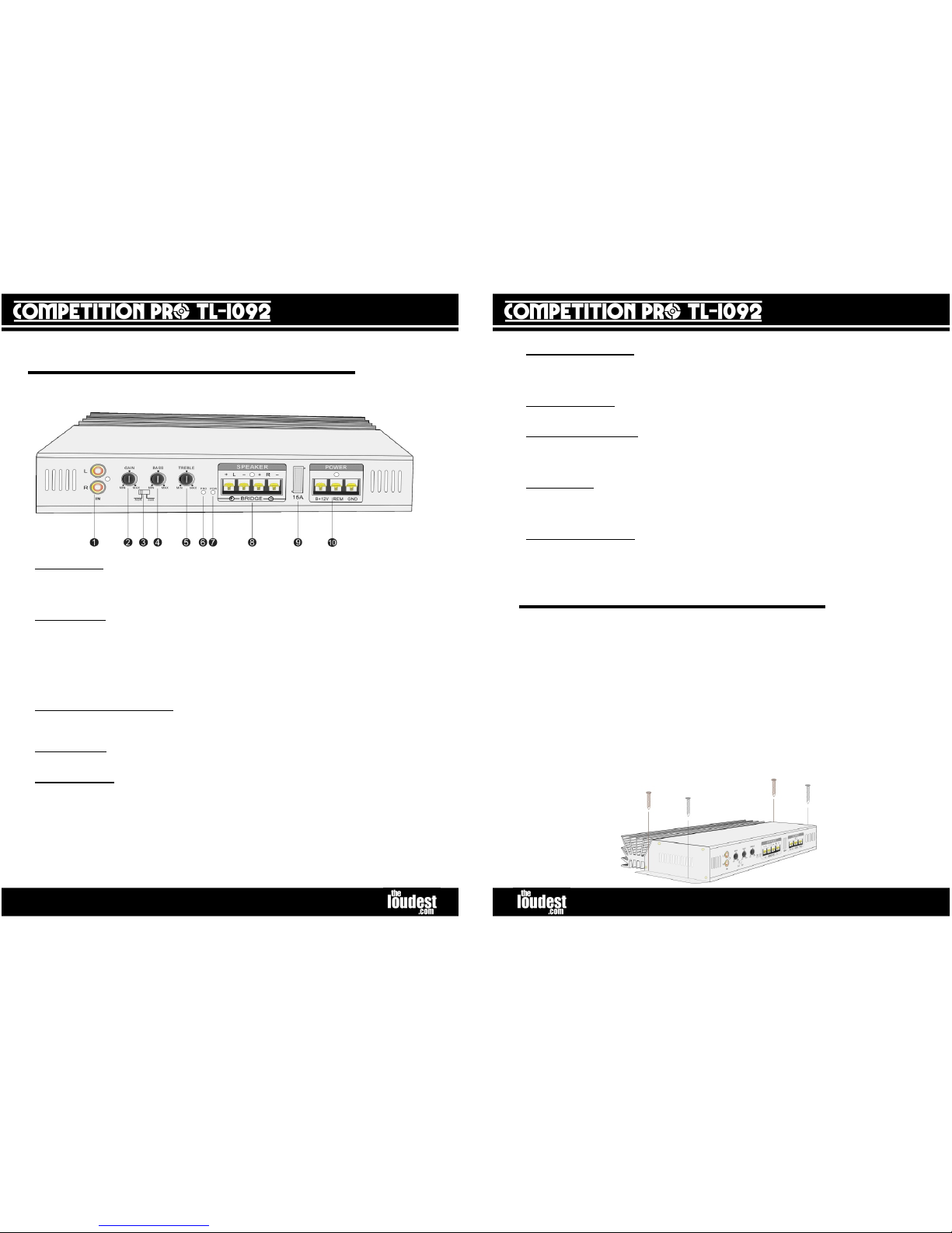
Control Panel Functions
1. Audio Input
- A source unit that supplies a “line level” (pre amp) audio output in the
form of RCA phono plugs is required to connect here (via a phono extension lead). A high
quality shielded lead is recommended as this will help reduce the possibility of noise
entering the system.
2. Gain Control - Turning the knob to the right (clockwise) will increase the volume, and
to the left (anti-clockwise) will reduce the volume. It is important to understand that
the amount of gain needed is proportional to the level of the signal coming from the
source unit. For example, it is possible for the gain knob to be at only a quarter of its
maximum, but the amplifier is actually outputting to its full potential. This could be
because the source unit is supplying slightly more power than normally expected.
Please see “Installation” section for how to calibrate the amplifier to the output of the
source unit using the gain knob.
3. Normal/Subwoofer Switch - When powering a subwoofer, it is advisable to switch to
subwoofer mode. The amplifier employs a low-pass filter which cuts out the frequencies
other than bass. This enables the subwoofer to function more efficiently.
4. Bass Control - This knob controls the level of the bass. Turn to the right (clockwise) to
increase the bass volume, or turn to the left (anti-clockwise) to decrease the bass volume.
5. Treble Control - This knob controls the level of the treble (the high frequencies). Turn
to the right (clockwise) to increase the treble volume, or turn to the left (anti-clockwise) to
decrease the treble volume. This can be used in conjunction with the bass control to tailor
the output to the surroundings of the car, or listening preference.
If more than one amplifier is used, one could be used to reproduce the bass frequencies
through a subwoofer and the other one used to play only treble through midrange
speakers or tweeters.
The control panel for the TL-1092 is as follows:
OWNER’S MANUAL
6. Protection Indicator
- This LED will light if the amplifier has detected a fault and has
shut down to protect itself from permanent damage. This will be due to one of the
following: excessive heat, DC offset, short circuit or input overload. If this happens
disconnect the amplifier and investigate the problem.
7. Power Indicator - This LED will light when power, remote and earth are all connected
to the amplifier. If this LED is not on, there is a problem with one of these connections.
8. Speaker Connections - These are screw terminals for attaching the speaker cables.
Undo the screw head enough to slot a stripped end of speaker cable into the terminal, and
then tighten the screw. Please see wiring diagrams in the “Installation” section for how to
connect speakers to the amplifier.
9. Power Fuse - This ATC fuse is to protect the amplifier against overdrive. In the event
that the fuse blows, it would be advisable to replace it with one of the same value.
An additional fuse is required between the battery and the amplifier. This comes as
standard in amplifier wiring kits.
10. Power Connections – This is where all the power leads are connected to the
amplifier. Particular care must be taken when connecting, NOT to cross any of the cables.
“B+12” is the positive connection from the battery. “GND” is the negative or earth
connection and “REM” is the remote or ignition connection.
Mounting Instructions
Before mounting, please read the “Installation” section. The best place to mount the
amplifier is somewhere where it will not get damaged by the feet of passengers or by
items in the boot of the vehicle. The amplifier dissipates heat using its heat sink;
somewhere with sufficient space and air would be fine. Therefore placing the amplifier in
between items, placing items on top of it, or mounting it upside down is not advisable.
Examples of surfaces are: the floor of the boot, fake floor of boot (MDF), side of subwoofer
box, side of boot, high in the passenger footwell or under a front seat. Never mount the
amplifier outside of the car, in the engine bay or anywhere where it has a risk of getting
wet. Normally it is best to attach the amplifier to a board, and then attach the board to
the car body. This is good practice to avoid noise problems.
Before mounting, make sure that the surface is suitable and free from any obstructions.
Use the amplifier as a template and mark where the holes are to be drilled with a pencil or
pen. Drill the pilot holes with a drill bit of diameter smaller than that of the screws.
Then place the amplifier on the surface and tighten the screws (as illustrated below) until
they are holding the amplifier securely in place.

OWNER’S MANUAL
Installation
Installation for a single speaker such as a subwoofer is nearly identical to the
above; however the speaker outputs are bridged, as illustrated below:
The completed installation for the TL-1092 powering two speakers is as
follows:
OWNER’S MANUAL
If you do not have sufficient experience or tools to carry out the installation, it is
strongly advised that you seek the assistance of someone who does, or have the
amplifier professionally installed.
Before starting the installation it is advisable to disconnect the negative terminal of
the vehicle battery. This ensures the battery will not short if the wires are accidentally
crossed during installation, and is generally good practice when making electrical changes.
Please be warned that after disconnecting the battery, your control unit (head unit) may
require a code to be entered, some car alarms may also sound. Therefore it is best to
disable the alarm before installation and enable it again after installation is complete.
To complete the installation, an “Amplifier Wiring Kit” is needed (not supplied with the
amplifier); this supplies all necessary cables:
- Power cable (fused)
- Ground Cable
- RCA (phono) cable
- Remote turn on wire
- Speaker cable
Connect the power (+) cable (normally thick red wire) directly to the positive terminal
of your vehicle battery by unscrewing the nut on positive terminal and slipping on the
power lead connector, before replacing and tightening the nut. There should be a fuse
holder and fuse already installed on this wire if purchased as part of a wiring kit. If not,
you will need to install one.
This power cable then needs to be run to where the amplifier will be mounted. Look
around the engine bay for a place to run the cable through to the inside of the vehicle.
Suitable points are usually bonnet pull grommets or air intake holes. This positive wire
needs to be protected from damage. Failure to protect it from damage could lead to a
vehicle fire. When you have been able to feed the cable to the inside of the car, try to
hide the cable as well as possible on its way to the amplifier (under carpet, or inside
panels).
The wiring kit should have supplied connectors to crimp on to the end of the power cable
for connecting it to the amplifier. If you are sure of the positioning of the amplifier, cut
the power cable to length and attach the connector. Un-tighten the power (B+) terminal
of the amplifier, slide the connector in, and then tighten. If there are no connectors
supplied or they are unsuitable, strip the end of the cable and slide the end into the power
(B+) terminal of the amplifier.
Competition Pro amplifiers are capable of delivering extremely high power levels.
Therefore tight, reliable and clean power connections at both ends are very important, and
ensure maximum performance.
Connect the earth (-) (or ground) cable (normally thick black wire) to a solid, bare
metal point on the vehicle’s chassis. A common place for this is the boot catch; however
any existing bolt or screw that makes contact with the car’s body near the amplifier is
sufficient. If there is no existing point, you can make one by drilling into the car’s body.
This should be done carefully as a last resort, ensuring that none of the car’s electronics or
any other component is going to be damaged. A clean connection is required, so scraping
away the paint for the connection is required. Run the cable to the amplifier and cut it to
length. Connect the power cable to the “GND” terminal on the amplifier using connectors
or the stripped end, as described for the power cable.

OWNER’S MANUAL
Connect the remote cable (normally thin blue wire) from the source unit (head unit)’s
remote output. This is called a variety of things including “remote”, “aerial”, “electric
antenna”, “REM” and “remote turn on”. To do this you will need to have access to the
back of the source unit; it will need pulled out. Please refer to the source unit’s manual to
find the right cable.
When the remote cable is attached to the remote output of the source unit, leave the
source unit pulled out for the moment, and run the remote cable to where the amplifier is,
down the same side of the vehicle as the power cable. As with the power cable, try to hide
it under panels and carpet. Again, the wiring kit should have been supplied with
connectors, so cut the cable to length and connect it to the “REM” terminal on the
amplifier, with or without a connector, in the same manner as the power and ground
cables were connected.
Connect the audio signal lead (RCA phono lead) to the “line level” or “pre-out” of the
source unit. The pre-out of the source unit should be in the form of two RCA phono
sockets. Simply plug your lead into the sockets, ensuring red goes to red, and white (or
black) goes to white (or black).
Then run the lead all the way to the amplifier. To minimise noise, please ensure that the
audio signal lead is run well away from the power leads. It is normally best to run it
down the opposite side of the car. If the cables are too close, a high pitched
whine can get into the system; this is engine noise.
If your source unit has no pre-outs, it is probable that it is not of sufficient quality to work
well with an amplifier; if it is giving poor quality audio then the amplifier will simply
amplify this poor quality audio. However, if a line output converter is purchased, it would
convert speaker outputs to a line level and enable you to operate the amplifier. As
mentioned, the output may not be of a great quality.
Connect the speaker cable from your speaker(s) to the amplifier. Negative should go to
negative and positive to positive, as illustrated on page 5. It is advisable to cut the
speaker cable to size. However, make sure that the same length is used for each speaker.
Never connect or disconnect speakers when the amplifier is on; you risk
permanently damaging the speakers.
Once you have checked that all the connections are good and solid, re-connect the
negative terminal of the battery. If anything goes wrong, disconnect it immediately and
investigate. The amplifier’s power LED should be lit. If not, or the protection LED is lit,
please refer to the “Troubleshooting” section.
Finally, all that is left to do is calibrate the amplifier with the source unit:
1. Turn the gain knob on the amplifier all the way down
2. Play a CD or similar of music or audio that will be typically played
3. Turn the gain control on the source unit to around 70 – 80% of it’s maximum
4. Slowly increase the gain knob on the amplifier until you can hear distortion
5. Turn the gain knob on the amplifier to just before this distortion occurs
6. Test the system and make any equalisation changes on the source unit or the
amplifier according to taste
7. If any equalisation changes are made, repeat stages 1 to 7 until satisfied
8. Never exceed the source unit gain that you used to calibrate the system
Remember: It is possible for the gain knob to be at only a quarter of its maximum, but
the amplifier is actually outputting to its full potential. This could be because the source
unit is supplying slightly more power than normally expected.
OWNER’S MANUAL
Safety
Health Warning
The Competition Pro range of car audio is built for very high power handling. Listening to
music at such high powers is potentially capable of causing physical side effects such as
nausea or even permanent side effects such as hearing loss. It is therefore absolutely
essential that conservatism and a high sense of judgement is observed when in operation.
TheLoudest.com accepts no liability for hearing disorders, nausea or other side effects
caused by this equipment.
General Safety
Playing loud music in a vehicle can hinder your sense of what is going on around you on
the road, including your ability to hear your own, and other vehicles. We recommend
listening at low or moderate levels while driving.
TheLoudest.com accepts no liability for injury, property damage or otherwise resulting
from the use or misuse of this equipment.
Do not use any chemicals when cleaning this equipment. Please use a clean dry cloth.
Do not install this unit outside the car, or anywhere where it could become damp or humid,
or where it can become exposed to the sun. It should be installed in a dry and ventilated
area inside the car.
Never connect or disconnect speakers when the amplifier is on; this can permanently
damage the speakers. Always do this when it is off.
Never open the amplifier up. Doing so would put you at risk of an electric shock. None of
the internal parts are serviceable by the user. In the case of the unit needing repair or
maintenance, please take it to a qualified professional.

OWNER’S MANUAL
Troubleshooting
Problem
Possible Cause(s) Solution
Power LED off No (or poor) power, remote
or ground connections
Blown fuse
Verify connections both at amplifier
and at other ends
Replace Fuse
No Output
(Power LED on)
Speakers not connected
Gain down on either
amplifier or source unit
Speaker(s) blown
Verify speaker connections at
amplifier, and also at the speakers
Verify gain/eq controls
Disconnect speakers one at a time to
pinpoint defective speaker
No Output
(Protect LED on)
Amplifier is overheated
Vehicle’s battery is
supplying something other
than 12V
Review mounting position and
conditions
Check vehicle’s battery and charging
system
Distorted output Source unit/amplifier gain
set too high
Source unit is not capable of
good audio reproduction
Speaker(s) blown
Re-calibrate amplifier
Replace/upgrade source unit
Disconnect speakers one at a time to
pinpoint defective speaker
Bass is weak Speakers wired out of phase
Eq settings are reducing
bass power
Check the + and – connections all
match
Return all eq settings on amplifier and
source unit to default
Blowing fuses Excessive output levels Lower gain
If your amplifier is still not functioning correctly after checking through the
“troubleshooting” section, please contact our support team at:
support@theloudest.co.uk
OWNER’S MANUAL
Technical Specifications
Maximum output power 2 x 750 Watts @ 2 ohms
2 x 500 Watts @ 4 ohms
Maximum output power (bridged) 1 x 1000 Watts @ 4 ohms
Frequency response 20Hz ~ 20KHz ± 1 dB
Input sensitivity < 200 mV
Signal/Noise Ratio 98 dB
Separation Scale > 50 dB
Speaker impedance Stereo output: 2 ~ 16 Ω
Bridged output: 4 ~ 16 Ω
Treble control: 10 KHz ± 10 dB
Bass control: 100 Hz ± 10 dB
Power supply DC 12V
Dimensions:
(length x width x height)
280 x 200 x 50 mm
Features
2 channel input
2 channel output
Stereo/bridged output
Gold plated low level input terminals
Treble/bass/gain control circuit
Normal/Super subwoofer output transition control switch
Aluminium heat-sink
Protection indicator
Thermal overheat/overload/short circuit protection functions
External fuse
Field-effect high performance power supply circuit
Power supply indicator
12V power supply
Table of contents
Other TheLoudest.com Car Amplifier manuals


Popular Car Amplifier manuals by other brands


Diamond Audio Technology
Diamond Audio Technology D7054 installation manual

MB QUART
MB QUART FORMULA FX1.400 installation manual

Kenwood
Kenwood KAC-PS810D instruction manual

Focal
Focal FPS 4160 Characteristics

Competition Pro
Competition Pro TL-2092 owner's manual

Sony
Sony XM-D1000P5 Marketing Specifications operating instructions