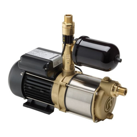
Theralux Theraflo TVS 1hp User manual

Instrucon
Manual
1hp & 1.5hp
This user manual shall not be reproduced without the
prior permission of Internaonal Quadracs.
Internaonal Quadracs
www.theralux.com.au
1300 131 788

2
THERAFLO REPLACEMENT PARTS DIAGRAM THERAFLO REPLACEMENT PARTS TABLE
REF NO. PART NO. DESCRIPTION
1 & 2 THERAF4320 Hand Knob Kit for Strainer Cover (inc Hand Knob &
Swivel Nut)
3 THERAF4304 Strainer Cover, Hand Knob Style - Clear
4 THERAF4303 Strainer Cover O-Ring
5 THERAF4302 Basket
6 THERAF4301B Pump Housing/Strainer - 50mm, w/Drain Plugs, threaded
external
7 & 8 THERAF4318 Drain Plug with O-Ring
9 THERAF4317 Mounting Foot Cap Screw (set of 2)
10 THERAF4316B Mounting Bracket, hps style
11 THERAF4323 Spacer for motor support (required only for 1hp model)
12, 13, 14 THERAF4321 Union Kit (set of 2) suit 40mm & 50mm w/Gasket (T-Seal)
15 THERAF4322 Union Gasket (T-Seal)
16 THERAF4305 Housing Gasket
17 THERAF4323B Diffuser Gasket
18 THERAF4306C Diffuser
19 THERAF4307B Impeller Ring
20 THERAF4308K Impeller 1HPVS (required only for 1hp model)
21 THERAF4309B Seal Assembly (inc, Mechanical Seal and Slinger)
22 THERAF4312B Slinger
23 THERAF4310B Seal Plate
24 THERAF4311B Motor Cap Screw (4 required)
25 THERAF4313B Motor Mounting Plate
26 THERAF4315K Motor 1HPVS (required only for 1hp model)
27 THERAF4314 Housing Cap Screw (6 required)
THERAF4308H Impeller 1.5HPVS (required only for 1.5hp model)
THERAF4315L Motor 1.5HPVS (required only for 1.5hp model)

3
THERAFLO REPLACEMENT PARTS DIAGRAM THERAFLO REPLACEMENT PARTS TABLE
REF NO. PART NO. DESCRIPTION
1 & 2 THERAF4320 Hand Knob Kit for Strainer Cover (inc Hand Knob &
Swivel Nut)
3 THERAF4304 Strainer Cover, Hand Knob Style - Clear
4 THERAF4303 Strainer Cover O-Ring
5 THERAF4302 Basket
6 THERAF4301B Pump Housing/Strainer - 50mm, w/Drain Plugs, threaded
external
7 & 8 THERAF4318 Drain Plug with O-Ring
9 THERAF4317 Mounting Foot Cap Screw (set of 2)
10 THERAF4316B Mounting Bracket, hps style
11 THERAF4323 Spacer for motor support (required only for 1hp model)
12, 13, 14 THERAF4321 Union Kit (set of 2) suit 40mm & 50mm w/Gasket (T-Seal)
15 THERAF4322 Union Gasket (T-Seal)
16 THERAF4305 Housing Gasket
17 THERAF4323B Diffuser Gasket
18 THERAF4306C Diffuser
19 THERAF4307B Impeller Ring
20 THERAF4308K Impeller 1HPVS (required only for 1hp model)
21 THERAF4309B Seal Assembly (inc, Mechanical Seal and Slinger)
22 THERAF4312B Slinger
23 THERAF4310B Seal Plate
24 THERAF4311B Motor Cap Screw (4 required)
25 THERAF4313B Motor Mounting Plate
26 THERAF4315K Motor 1HPVS (required only for 1hp model)
27 THERAF4314 Housing Cap Screw (6 required)
THERAF4308H Impeller 1.5HPVS (required only for 1.5hp model)
THERAF4315L Motor 1.5HPVS (required only for 1.5hp model)
CONTENTS
THERAFLO INTRODUCTION 8
THERAFLO INSTALLATION 9
THERAFLO START UP 10
THERAFLO CONTROL PANEL 11
THERAFLO TRUE VARIABLE SPEED CONTROL 12
THERAFLO REPLACEMENT PARTS DIAGRAM 15
INTRODUCTION
The Theraflo TVS swimming pool pump has been specifically designed with the
consumer in mind. With the Australian electricity and water usage costs always
increasing, it was necessary to provide our users with a swimming pool pump
that is manually adjustable to the speeds they desired. By ulising this feature,
our users can save money on their electricity and water bills, as well as
experience an efficient, longer lasng life on their pool pump motor.
The Theraflo TVS is a great combinaon of tried and tested wet end technology
with the smart innovaon of TVS (True Variable Speed) motor adjustment.
At first glance, the large and robust wet end exemplifies high quality. Australian
made from high tensile plasc, our wet end is extremely tough and is designed
for longer lasng life. Our revoluonary clamp and screw down clear lid provide
for easy access to the hair and lint basket which makes maintenance a breeze.
Our motor is designed for maximum energy efficiency and is controlled by a
simple to use control pad that provides total adjustment at the push of a buon.
The Theraflo TVS swimming pool pump is part of the unique Australian designed
Theralux swimming pool sanitaon system, which focuses on providing the
healthiest swimming pool environments possible for our users. This is achieved
through the calibraon of hundreds of years industry experience, allowing us to
challenge the realms of industry normality.
SHAFT SEAL REPLACEMENT 13
SEAL, IMPELLER AND DIFFUSER INSTALLATION 14
IMPORTANT SAFETY INSTRUCTIONS 4
THERAFLO REPLACEMENT PARTS TABLE 16
THERAFLO CARE AND MAINTENANCE 17
THERAFLO WARRANTY 18

4
THERAFLO REPLACEMENT PARTS DIAGRAM THERAFLO REPLACEMENT PARTS TABLE
REF NO. PART NO. DESCRIPTION
1 & 2 THERAF4320 Hand Knob Kit for Strainer Cover (inc Hand Knob &
Swivel Nut)
3 THERAF4304 Strainer Cover, Hand Knob Style - Clear
4 THERAF4303 Strainer Cover O-Ring
5 THERAF4302 Basket
6 THERAF4301B Pump Housing/Strainer - 50mm, w/Drain Plugs, threaded
external
7 & 8 THERAF4318 Drain Plug with O-Ring
9 THERAF4317 Mounting Foot Cap Screw (set of 2)
10 THERAF4316B Mounting Bracket, hps style
11 THERAF4323 Spacer for motor support (required only for 1hp model)
12, 13, 14 THERAF4321 Union Kit (set of 2) suit 40mm & 50mm w/Gasket (T-Seal)
15 THERAF4322 Union Gasket (T-Seal)
16 THERAF4305 Housing Gasket
17 THERAF4323B Diffuser Gasket
18 THERAF4306C Diffuser
19 THERAF4307B Impeller Ring
20 THERAF4308K Impeller 1HPVS (required only for 1hp model)
21 THERAF4309B Seal Assembly (inc, Mechanical Seal and Slinger)
22 THERAF4312B Slinger
23 THERAF4310B Seal Plate
24 THERAF4311B Motor Cap Screw (4 required)
25 THERAF4313B Motor Mounting Plate
26 THERAF4315K Motor 1HPVS (required only for 1hp model)
27 THERAF4314 Housing Cap Screw (6 required)
THERAF4308H Impeller 1.5HPVS (required only for 1.5hp model)
THERAF4315L Motor 1.5HPVS (required only for 1.5hp model)
IMPORTANT SAFETY INSTRUCTIONS
WARNING – Risk of Electric Shock. All electrical
wiring must be performed by a qualified electrical
contractor, and must conform to Local/State/Federal
electrical regulaons and the Latest Edion of AS/NZ
3000 Wiring Rules. All electrical circuits must be supplied
through a Residual Current Device - RCD (Safety Switch),
with a residual operang current not exceeding 30 mA.
Hazardous voltage can shock, burn and cause death or
serious property damage. To reduce the risk of electric
shock, do NOT use an extension cord to connect unit to
the electricity supply.
WARNING – To reduce the risk of electric shock replace damaged
wiring immediately. Locate the power cord so that it cannot be damaged by lawn
mowers, hedge trimmers and other equipment.
WARNING – Never operate the circulaon system at more than 344
kPa (50 PSI) maximum.
WARNING – Automac Restart. The pump motor is automacally
protected from overheang. If such an error occurs, the pump will automacally
restart once the temperature is at a safe level to do so without warning. If a
power failure occurs while the pump is running, it will automacally restart once
the power has been restored.
WARNING – Damaged Supply Cord. If the power supply cord is
damaged it must be replaced by the manufacturer, its service agent or similarly
qualified persons in order to avoid a hazard.
Before installing or servicing this electrical equipment, disconnect it from the power supply
WARNING – This manual contains important informaon about the
installaon, operaon, and safe use of this pump that must be transferred
through to the end user of this product.
WARNING – This product should be installed and serviced only by a
qualified professional.
WARNING – All electrical wiring MUST be performed by a qualified
electrical contractor, and must conform to Local/State/Federal electrical
regulaons and the Latest Edion of AS/NZS 3000 Wiring Rules.
WARNING – This appliance is not intended for use by persons
(including children) with reduced physical, sensory or mental capabilites, or lack
of experience and knowledge, unless they have been given supervision or
instrucon concerning use of the appliance by a person responsible for their
safety. CHILDREN SHOULD BE SUPERVISED TO ENSURE THAT THEY DO NOT
PLAY WITH THE APPLIANCE.
CAUTION – This pump is intended for use on permanently installed
swimming pools and may also be used with hot tubs and spas if so marked. Do
NOT use with storable pools. A permanently installed pool is constructed in or on
the ground or in a building such that it cannot be readily disassembled for
storage. A storable pool is constructed so that it is capable of being readily
disassembled for storage and reassembled to its original integrity. Though this
product is designed for outdoor use, it is strongly advised to protect the electrical
components from the weather. Select a well-drained area, one that will not flood
when it rains. It requires free circulaon of air for cooling. Do not install in a damp
or non-venlated locaon. If installed within an outer enclosure or beneath the
skirt of a hot tub or spa, adequate venlaon and free circulaon of air must be
provided to prevent overheang of the motor.
WARNING – Pool and spa components have a finite life. All
components should be inspected frequently and replaced at least every ten
years, or if found to be damaged, broken, cracked, missing, or not securely
aached.
Before installing or servicing this electrical equipment, disconnect it from the power supply
WARNING
Read and follow all instrucons in this owner’s manual and
on the equipment. Failure to follow instrucons can cause
severe injury and/or death.
MAXIMUM TOTAL HEAD
Model Max. Total Head Input kW Inpu t
Amps
Noise
dB(A) 1m (kg)
Weight Ingress
Protection
VS 1hp 15.5m - 152kPa 1.03kW 6.0 < 70 11 IPX5
VS 1.5hp 16.5m - 162kPa 1.08kW 7.0 < 70 12.4 IPX5

5
THERAFLO REPLACEMENT PARTS DIAGRAM THERAFLO REPLACEMENT PARTS TABLE
REF NO. PART NO. DESCRIPTION
1 & 2 THERAF4320 Hand Knob Kit for Strainer Cover (inc Hand Knob &
Swivel Nut)
3 THERAF4304 Strainer Cover, Hand Knob Style - Clear
4 THERAF4303 Strainer Cover O-Ring
5 THERAF4302 Basket
6 THERAF4301B Pump Housing/Strainer - 50mm, w/Drain Plugs, threaded
external
7 & 8 THERAF4318 Drain Plug with O-Ring
9 THERAF4317 Mounting Foot Cap Screw (set of 2)
10 THERAF4316B Mounting Bracket, hps style
11 THERAF4323 Spacer for motor support (required only for 1hp model)
12, 13, 14 THERAF4321 Union Kit (set of 2) suit 40mm & 50mm w/Gasket (T-Seal)
15 THERAF4322 Union Gasket (T-Seal)
16 THERAF4305 Housing Gasket
17 THERAF4323B Diffuser Gasket
18 THERAF4306C Diffuser
19 THERAF4307B Impeller Ring
20 THERAF4308K Impeller 1HPVS (required only for 1hp model)
21 THERAF4309B Seal Assembly (inc, Mechanical Seal and Slinger)
22 THERAF4312B Slinger
23 THERAF4310B Seal Plate
24 THERAF4311B Motor Cap Screw (4 required)
25 THERAF4313B Motor Mounting Plate
26 THERAF4315K Motor 1HPVS (required only for 1hp model)
27 THERAF4314 Housing Cap Screw (6 required)
THERAF4308H Impeller 1.5HPVS (required only for 1.5hp model)
THERAF4315L Motor 1.5HPVS (required only for 1.5hp model)
IMPORTANT SAFETY INSTRUCTIONS
WARNING – Risk of Electric Shock. All electrical
wiring must be performed by a qualified electrical
contractor, and must conform to Local/State/Federal
electrical regulaons and the Latest Edion of AS/NZ
3000 Wiring Rules. All electrical circuits must be supplied
through a Residual Current Device - RCD (Safety Switch),
with a residual operang current not exceeding 30 mA.
Hazardous voltage can shock, burn and cause death or
serious property damage. To reduce the risk of electric
shock, do NOT use an extension cord to connect unit to
the electricity supply.
WARNING – To reduce the risk of electric shock replace damaged
wiring immediately. Locate the power cord so that it cannot be damaged by lawn
mowers, hedge trimmers and other equipment.
WARNING – Never operate the circulaon system at more than 344
kPa (50 PSI) maximum.
WARNING – Automac Restart. The pump motor is automacally
protected from overheang. If such an error occurs, the pump will automacally
restart once the temperature is at a safe level to do so without warning. If a
power failure occurs while the pump is running, it will automacally restart once
the power has been restored.
WARNING – Damaged Supply Cord. If the power supply cord is
damaged it must be replaced by the manufacturer, its service agent or similarly
qualified persons in order to avoid a hazard.
Before installing or servicing this electrical equipment, disconnect it from the power supply
WARNING – This manual contains important informaon about the
installaon, operaon, and safe use of this pump that must be transferred
through to the end user of this product.
WARNING – This product should be installed and serviced only by a
qualified professional.
WARNING – All electrical wiring MUST be performed by a qualified
electrical contractor, and must conform to Local/State/Federal electrical
regulaons and the Latest Edion of AS/NZS 3000 Wiring Rules.
WARNING – This appliance is not intended for use by persons
(including children) with reduced physical, sensory or mental capabilites, or lack
of experience and knowledge, unless they have been given supervision or
instrucon concerning use of the appliance by a person responsible for their
safety. CHILDREN SHOULD BE SUPERVISED TO ENSURE THAT THEY DO NOT
PLAY WITH THE APPLIANCE.
CAUTION – This pump is intended for use on permanently installed
swimming pools and may also be used with hot tubs and spas if so marked. Do
NOT use with storable pools. A permanently installed pool is constructed in or on
the ground or in a building such that it cannot be readily disassembled for
storage. A storable pool is constructed so that it is capable of being readily
disassembled for storage and reassembled to its original integrity. Though this
product is designed for outdoor use, it is strongly advised to protect the electrical
components from the weather. Select a well-drained area, one that will not flood
when it rains. It requires free circulaon of air for cooling. Do not install in a damp
or non-venlated locaon. If installed within an outer enclosure or beneath the
skirt of a hot tub or spa, adequate venlaon and free circulaon of air must be
provided to prevent overheang of the motor.
WARNING – Pool and spa components have a finite life. All
components should be inspected frequently and replaced at least every ten
years, or if found to be damaged, broken, cracked, missing, or not securely
aached.
Before installing or servicing this electrical equipment, disconnect it from the power supply
WARNING
Read and follow all instrucons in this owner’s manual and
on the equipment. Failure to follow instrucons can cause
severe injury and/or death.
MAXIMUM TOTAL HEAD
Model Max. Total Head Input kW Inpu t
Amps
Noise
dB(A) 1m (kg)
Weight Ingress
Protection
VS 1hp 15.5m - 152kPa 1.03kW 6.0 < 70 11 IPX5
VS 1.5hp 16.5m - 162kPa 1.08kW 7.0 < 70 12.4 IPX5

6
THERAFLO REPLACEMENT PARTS DIAGRAM THERAFLO REPLACEMENT PARTS TABLE
REF NO. PART NO. DESCRIPTION
1 & 2 THERAF4320 Hand Knob Kit for Strainer Cover (inc Hand Knob &
Swivel Nut)
3 THERAF4304 Strainer Cover, Hand Knob Style - Clear
4 THERAF4303 Strainer Cover O-Ring
5 THERAF4302 Basket
6 THERAF4301B Pump Housing/Strainer - 50mm, w/Drain Plugs, threaded
external
7 & 8 THERAF4318 Drain Plug with O-Ring
9 THERAF4317 Mounting Foot Cap Screw (set of 2)
10 THERAF4316B Mounting Bracket, hps style
11 THERAF4323 Spacer for motor support (required only for 1hp model)
12, 13, 14 THERAF4321 Union Kit (set of 2) suit 40mm & 50mm w/Gasket (T-Seal)
15 THERAF4322 Union Gasket (T-Seal)
16 THERAF4305 Housing Gasket
17 THERAF4323B Diffuser Gasket
18 THERAF4306C Diffuser
19 THERAF4307B Impeller Ring
20 THERAF4308K Impeller 1HPVS (required only for 1hp model)
21 THERAF4309B Seal Assembly (inc, Mechanical Seal and Slinger)
22 THERAF4312B Slinger
23 THERAF4310B Seal Plate
24 THERAF4311B Motor Cap Screw (4 required)
25 THERAF4313B Motor Mounting Plate
26 THERAF4315K Motor 1HPVS (required only for 1hp model)
27 THERAF4314 Housing Cap Screw (6 required)
THERAF4308H Impeller 1.5HPVS (required only for 1.5hp model)
THERAF4315L Motor 1.5HPVS (required only for 1.5hp model)
IMPORTANT SAFETY INSTRUCTIONS
Before installing or servicing this electrical equipment, disconnect it from the power supply
WARNING – Hazardous Pressure. Pool and spa water circulaon
systems operate under hazardous pressure during
start-up, normal operaon, and aer pump shut-off.
Stand clear of circulaon system equipment during pump
start-up. Failure to follow safety and operaon
instrucons could result in violent separaon of the
pump housing and cover due to pressure in the system.
This separaon could cause property damage, severe
personal injury, or death. Before servicing the pool and
spa water circulaon system, all system and pump
controls must be in the off posion and the Filter Manual
Air Relief Valve must be in the open posion. Before
starng the system pump, all valves must be set in a
posion to allow system water to return back to the pool.
Do not change the Filter Control Valve posion while the
system pump is running. Before starng the system
pump, fully open the Filter Manual Air Relief Valve. Do
not close the Filter Manual Air Relief valve unl all the air
is expelled and a steady stream of water is discharged
from the valve. All sucon and discharge valves MUST BE
OPEN when starng the circulaon system. Failure to do
so could result in severe personal injury and/or property
damage.
WARNING – Separaon Hazard. Failure to follow safety and operaon
instrucons could result in violent separaon of pump
components. Strainer cover must be properly secured to
pump housing by ensuring it is firmly screwed down.
Before servicing pool and spa circulaon system, all
system and pump controls must be in off posion and
the Filter Manual Air Relief Valve must be in open
posion. Do not operate pool and spa circulaon system
if system components are not assembled properly,
damaged, or missing. Do not operate pool and spa
circulaon system unless the Filter Air Relief Valve body
is in locked posion within the filter upper body. All
sucon and discharge valves MUST BE OPEN when
starng the circulaon system. Failure to do so could
result in severe personal injury and/or property damage.
WARNING – Sucon Entrapment Hazard. The force from sucon in
sucon outlets and/or sucon outlet covers which are damaged, broken, cracked,
missing, or unsecured, can cause severe injury and/or death due to the following
entrapment hazards:
Hair Entrapment - Hair can become entangled in sucon outlet cover.
Limb Entrapment - A limb inserted into an opening of a sucon outlet
sump or sucon outlet cover that is damaged, broken, cracked, missing,
or not securely aached, can result in a mechanical bind or swelling of
the limb.
Body Sucon Entrapment - A differenal pressure applied to a large
poron of the body or limbs can result in an entrapment.
Evisceraon/Disembowelment - A negave pressure applied directly
to the intesnes through an unprotected sucon outlet sump or
sucon outlet cover which is damaged, broken, cracked, missing, or
unsecured, can result in evisceraon/disembowelment.
Mechanical Entrapment - There is potenal for jewelry, swimsuits, hair
decoraons, fingers, toes, or knuckles, to be caught in an opening of a
sucon outlet cover resulng in mechanical entrapment.
WARNING – To Reduce the risk of Entrapment Hazards:
» When outlets are small enough to be blocked by a person, a minimum of
two funconing sucon outlets per pump must be installed. Sucon outlets in
the same plane (i.e. floor or wall), must be installed a minimum of 0.91 metres
or three feet (3’) apart, as measured from near point to near point to avoid dual
blockage by a user.
» Dual sucon fings shall not be located on seang areas or on the
backrest for such seang areas.
» Never use pool or spa if any sucon outlet component is damaged,
broken, cracked, missing, or not securely aached.
» Replace damaged, broken, cracked, missing, or not securely aached
sucon outlet components immediately.
» In addion to installing two or more sucon outlets
per pump, follow all naonal, state, local regulaons
and AS 1926.3 Latest Edion.
» Installaon of a vacuum release or vent system,
which relieves entrapping sucon, is recommended.
Before installing or servicing this electrical equipment, disconnect it from the power supply

7
THERAFLO REPLACEMENT PARTS DIAGRAM THERAFLO REPLACEMENT PARTS TABLE
REF NO. PART NO. DESCRIPTION
1 & 2 THERAF4320 Hand Knob Kit for Strainer Cover (inc Hand Knob &
Swivel Nut)
3 THERAF4304 Strainer Cover, Hand Knob Style - Clear
4 THERAF4303 Strainer Cover O-Ring
5 THERAF4302 Basket
6 THERAF4301B Pump Housing/Strainer - 50mm, w/Drain Plugs, threaded
external
7 & 8 THERAF4318 Drain Plug with O-Ring
9 THERAF4317 Mounting Foot Cap Screw (set of 2)
10 THERAF4316B Mounting Bracket, hps style
11 THERAF4323 Spacer for motor support (required only for 1hp model)
12, 13, 14 THERAF4321 Union Kit (set of 2) suit 40mm & 50mm w/Gasket (T-Seal)
15 THERAF4322 Union Gasket (T-Seal)
16 THERAF4305 Housing Gasket
17 THERAF4323B Diffuser Gasket
18 THERAF4306C Diffuser
19 THERAF4307B Impeller Ring
20 THERAF4308K Impeller 1HPVS (required only for 1hp model)
21 THERAF4309B Seal Assembly (inc, Mechanical Seal and Slinger)
22 THERAF4312B Slinger
23 THERAF4310B Seal Plate
24 THERAF4311B Motor Cap Screw (4 required)
25 THERAF4313B Motor Mounting Plate
26 THERAF4315K Motor 1HPVS (required only for 1hp model)
27 THERAF4314 Housing Cap Screw (6 required)
THERAF4308H Impeller 1.5HPVS (required only for 1.5hp model)
THERAF4315L Motor 1.5HPVS (required only for 1.5hp model)
IMPORTANT SAFETY INSTRUCTIONS
Before installing or servicing this electrical equipment, disconnect it from the power supply
WARNING – Hazardous Pressure. Pool and spa water circulaon
systems operate under hazardous pressure during
start-up, normal operaon, and aer pump shut-off.
Stand clear of circulaon system equipment during pump
start-up. Failure to follow safety and operaon
instrucons could result in violent separaon of the
pump housing and cover due to pressure in the system.
This separaon could cause property damage, severe
personal injury, or death. Before servicing the pool and
spa water circulaon system, all system and pump
controls must be in the off posion and the Filter Manual
Air Relief Valve must be in the open posion. Before
starng the system pump, all valves must be set in a
posion to allow system water to return back to the pool.
Do not change the Filter Control Valve posion while the
system pump is running. Before starng the system
pump, fully open the Filter Manual Air Relief Valve. Do
not close the Filter Manual Air Relief valve unl all the air
is expelled and a steady stream of water is discharged
from the valve. All sucon and discharge valves MUST BE
OPEN when starng the circulaon system. Failure to do
so could result in severe personal injury and/or property
damage.
WARNING – Separaon Hazard. Failure to follow safety and operaon
instrucons could result in violent separaon of pump
components. Strainer cover must be properly secured to
pump housing by ensuring it is firmly screwed down.
Before servicing pool and spa circulaon system, all
system and pump controls must be in off posion and
the Filter Manual Air Relief Valve must be in open
posion. Do not operate pool and spa circulaon system
if system components are not assembled properly,
damaged, or missing. Do not operate pool and spa
circulaon system unless the Filter Air Relief Valve body
is in locked posion within the filter upper body. All
sucon and discharge valves MUST BE OPEN when
starng the circulaon system. Failure to do so could
result in severe personal injury and/or property damage.
WARNING – Sucon Entrapment Hazard. The force from sucon in
sucon outlets and/or sucon outlet covers which are damaged, broken, cracked,
missing, or unsecured, can cause severe injury and/or death due to the following
entrapment hazards:
Hair Entrapment - Hair can become entangled in sucon outlet cover.
Limb Entrapment - A limb inserted into an opening of a sucon outlet
sump or sucon outlet cover that is damaged, broken, cracked, missing,
or not securely aached, can result in a mechanical bind or swelling of
the limb.
Body Sucon Entrapment - A differenal pressure applied to a large
poron of the body or limbs can result in an entrapment.
Evisceraon/Disembowelment - A negave pressure applied directly
to the intesnes through an unprotected sucon outlet sump or
sucon outlet cover which is damaged, broken, cracked, missing, or
unsecured, can result in evisceraon/disembowelment.
Mechanical Entrapment - There is potenal for jewelry, swimsuits, hair
decoraons, fingers, toes, or knuckles, to be caught in an opening of a
sucon outlet cover resulng in mechanical entrapment.
WARNING – To Reduce the risk of Entrapment Hazards:
» When outlets are small enough to be blocked by a person, a minimum of
two funconing sucon outlets per pump must be installed. Sucon outlets in
the same plane (i.e. floor or wall), must be installed a minimum of 0.91 metres
or three feet (3’) apart, as measured from near point to near point to avoid dual
blockage by a user.
» Dual sucon fings shall not be located on seang areas or on the
backrest for such seang areas.
» Never use pool or spa if any sucon outlet component is damaged,
broken, cracked, missing, or not securely aached.
» Replace damaged, broken, cracked, missing, or not securely aached
sucon outlet components immediately.
» In addion to installing two or more sucon outlets
per pump, follow all naonal, state, local regulaons
and AS 1926.3 Latest Edion.
» Installaon of a vacuum release or vent system,
which relieves entrapping sucon, is recommended.
Before installing or servicing this electrical equipment, disconnect it from the power supply

8
THERAFLO REPLACEMENT PARTS DIAGRAM THERAFLO REPLACEMENT PARTS TABLE
REF NO. PART NO. DESCRIPTION
1 & 2 THERAF4320 Hand Knob Kit for Strainer Cover (inc Hand Knob &
Swivel Nut)
3 THERAF4304 Strainer Cover, Hand Knob Style - Clear
4 THERAF4303 Strainer Cover O-Ring
5 THERAF4302 Basket
6 THERAF4301B Pump Housing/Strainer - 50mm, w/Drain Plugs, threaded
external
7 & 8 THERAF4318 Drain Plug with O-Ring
9 THERAF4317 Mounting Foot Cap Screw (set of 2)
10 THERAF4316B Mounting Bracket, hps style
11 THERAF4323 Spacer for motor support (required only for 1hp model)
12, 13, 14 THERAF4321 Union Kit (set of 2) suit 40mm & 50mm w/Gasket (T-Seal)
15 THERAF4322 Union Gasket (T-Seal)
16 THERAF4305 Housing Gasket
17 THERAF4323B Diffuser Gasket
18 THERAF4306C Diffuser
19 THERAF4307B Impeller Ring
20 THERAF4308K Impeller 1HPVS (required only for 1hp model)
21 THERAF4309B Seal Assembly (inc, Mechanical Seal and Slinger)
22 THERAF4312B Slinger
23 THERAF4310B Seal Plate
24 THERAF4311B Motor Cap Screw (4 required)
25 THERAF4313B Motor Mounting Plate
26 THERAF4315K Motor 1HPVS (required only for 1hp model)
27 THERAF4314 Housing Cap Screw (6 required)
THERAF4308H Impeller 1.5HPVS (required only for 1.5hp model)
THERAF4315L Motor 1.5HPVS (required only for 1.5hp model)
CONTENTS
THERAFLO INTRODUCTION 8
THERAFLO INSTALLATION 9
THERAFLO START UP 10
THERAFLO CONTROL PANEL 11
THERAFLO TRUE VARIABLE SPEED CONTROL 12
THERAFLO REPLACEMENT PARTS DIAGRAM 15
INTRODUCTION
The Theraflo TVS swimming pool pump has been specifically designed with the
consumer in mind. With the Australian electricity and water usage costs always
increasing, it was necessary to provide our users with a swimming pool pump
that is manually adjustable to the speeds they desired. By ulising this feature,
our users can save money on their electricity and water bills, as well as
experience an efficient, longer lasng life on their pool pump motor.
The Theraflo TVS is a great combinaon of tried and tested wet end technology
with the smart innovaon of TVS (True Variable Speed) motor adjustment.
At first glance, the large and robust wet end exemplifies high quality. Australian
made from high tensile plasc, our wet end is extremely tough and is designed
for longer lasng life. Our revoluonary clamp and screw down clear lid provide
for easy access to the hair and lint basket which makes maintenance a breeze.
Our motor is designed for maximum energy efficiency and is controlled by a
simple to use control pad that provides total adjustment at the push of a buon.
The Theraflo TVS swimming pool pump is part of the unique Australian designed
Theralux swimming pool sanitaon system, which focuses on providing the
healthiest swimming pool environments possible for our users. This is achieved
through the calibraon of hundreds of years industry experience, allowing us to
challenge the realms of industry normality.
SHAFT SEAL REPLACEMENT 13
SEAL, IMPELLER AND DIFFUSER INSTALLATION 14
IMPORTANT SAFETY INSTRUCTIONS 4
THERAFLO REPLACEMENT PARTS TABLE 16
THERAFLO CARE AND MAINTENANCE 17
THERAFLO WARRANTY 18

9
THERAFLO REPLACEMENT PARTS DIAGRAM THERAFLO REPLACEMENT PARTS TABLE
REF NO. PART NO. DESCRIPTION
1 & 2 THERAF4320 Hand Knob Kit for Strainer Cover (inc Hand Knob &
Swivel Nut)
3 THERAF4304 Strainer Cover, Hand Knob Style - Clear
4 THERAF4303 Strainer Cover O-Ring
5 THERAF4302 Basket
6 THERAF4301B Pump Housing/Strainer - 50mm, w/Drain Plugs, threaded
external
7 & 8 THERAF4318 Drain Plug with O-Ring
9 THERAF4317 Mounting Foot Cap Screw (set of 2)
10 THERAF4316B Mounting Bracket, hps style
11 THERAF4323 Spacer for motor support (required only for 1hp model)
12, 13, 14 THERAF4321 Union Kit (set of 2) suit 40mm & 50mm w/Gasket (T-Seal)
15 THERAF4322 Union Gasket (T-Seal)
16 THERAF4305 Housing Gasket
17 THERAF4323B Diffuser Gasket
18 THERAF4306C Diffuser
19 THERAF4307B Impeller Ring
20 THERAF4308K Impeller 1HPVS (required only for 1hp model)
21 THERAF4309B Seal Assembly (inc, Mechanical Seal and Slinger)
22 THERAF4312B Slinger
23 THERAF4310B Seal Plate
24 THERAF4311B Motor Cap Screw (4 required)
25 THERAF4313B Motor Mounting Plate
26 THERAF4315K Motor 1HPVS (required only for 1hp model)
27 THERAF4314 Housing Cap Screw (6 required)
THERAF4308H Impeller 1.5HPVS (required only for 1.5hp model)
THERAF4315L Motor 1.5HPVS (required only for 1.5hp model)
THERAFLO INSTALLATION
The Theraflo TVS comes with quick release connecng unions on both the inlet
and outlet which simplifies the installaon process. It also allows the user to
remove the pump at any me by simply unscrewing each union. This is handy for
any future maintenance.
The 2 connecng unions can be plumbed with either 40mm or 50mm PVC pipe.
Ideally, the pump will operate beer with the least amount of PVC bends and in
the closest proximity to the swimming pool available. Ensure the sucon pipe is
the same size or larger than the discharge pipe.
Installaon should be made on a level concrete slab or solid even surface with
the pump either bolted or screwed down.
There should be at least 100mm clearance between the rear of the pool pump
motor to allow for venlaon & cooling.
Connect the screw-on union to the pump inlet, clean the surface area with
priming soluon, and then glue together, using pressure PVC glue, the PVC
plumbing that comes from the swimming pool skimmer box.
Please note: Do not forget to use the union gasket provided.
Connect the screw-on union to the pump outlet, clean the surface area with
priming soluon, and then glue together, using pressure PVC glue, the PVC
plumbing line that connects to the filter inlet.
Please note: Do not forget to use the union gasket provided.
Connect the electrical power cable plug into your power supply – this may be a
power point or a salt water/mineral chlorinator.
Please note: Do not turn power on at this point.
Please allow enough me for the glue to set. Please check the PVC glue used for
ming direcons. However, we recommend you allow 6-8 hours for opmum
results.
All electrical wiring must be performed by a licensed electrical contractor and
must conform to the Latest Edion AS/NZS 3000 Wiring Rules.
THERAFLO START UP
Once the glue has had the required amount of seng me, check that both the
inlet and outlet connecon points are hand ght.
At this point, it is necessary to prime the pump wet end. This can be done by
unscrewing the 2 locking knobs & removing the clear plasc lid.
Fill the hair & lint pot area up with water unl it is completely full. This can be
pool water via a bucket or tap water from your hose.
Once full, please install the clear lid and ghten the locking knobs hand ght.
Check that ALL valves are in the open posion and that your filter mulpart valve
is set to FILTER.
It is now me to turn the power on (on the pump). This will either be via a power
point or chlorinator depending on the type of swimming pool you have.
The Theraflo TVS swimming pool pump will automacally start up in priming
speed (high speed) which will last for 5 minutes. Once the pool pump is primed,
you can then select the best suited speed for your swimming pool.
Please note: You need to ensure that you have enough water flow to provide
sufficient filtraon for your pool volume & system. The water flow provided can
be adjusted by simply changing the speed of the motor (refer to TVS control
page).
If you have a salt chlorinated pool, you also need to ensure that your salt cell is
always 100% full of water whilst the pump is in operaon. If you are unsure of
the above, please consult your local swimming pool professional.

10
THERAFLO REPLACEMENT PARTS DIAGRAM THERAFLO REPLACEMENT PARTS TABLE
REF NO. PART NO. DESCRIPTION
1 & 2 THERAF4320 Hand Knob Kit for Strainer Cover (inc Hand Knob &
Swivel Nut)
3 THERAF4304 Strainer Cover, Hand Knob Style - Clear
4 THERAF4303 Strainer Cover O-Ring
5 THERAF4302 Basket
6 THERAF4301B Pump Housing/Strainer - 50mm, w/Drain Plugs, threaded
external
7 & 8 THERAF4318 Drain Plug with O-Ring
9 THERAF4317 Mounting Foot Cap Screw (set of 2)
10 THERAF4316B Mounting Bracket, hps style
11 THERAF4323 Spacer for motor support (required only for 1hp model)
12, 13, 14 THERAF4321 Union Kit (set of 2) suit 40mm & 50mm w/Gasket (T-Seal)
15 THERAF4322 Union Gasket (T-Seal)
16 THERAF4305 Housing Gasket
17 THERAF4323B Diffuser Gasket
18 THERAF4306C Diffuser
19 THERAF4307B Impeller Ring
20 THERAF4308K Impeller 1HPVS (required only for 1hp model)
21 THERAF4309B Seal Assembly (inc, Mechanical Seal and Slinger)
22 THERAF4312B Slinger
23 THERAF4310B Seal Plate
24 THERAF4311B Motor Cap Screw (4 required)
25 THERAF4313B Motor Mounting Plate
26 THERAF4315K Motor 1HPVS (required only for 1hp model)
27 THERAF4314 Housing Cap Screw (6 required)
THERAF4308H Impeller 1.5HPVS (required only for 1.5hp model)
THERAF4315L Motor 1.5HPVS (required only for 1.5hp model)
THERAFLO INSTALLATION
The Theraflo TVS comes with quick release connecng unions on both the inlet
and outlet which simplifies the installaon process. It also allows the user to
remove the pump at any me by simply unscrewing each union. This is handy for
any future maintenance.
The 2 connecng unions can be plumbed with either 40mm or 50mm PVC pipe.
Ideally, the pump will operate beer with the least amount of PVC bends and in
the closest proximity to the swimming pool available. Ensure the sucon pipe is
the same size or larger than the discharge pipe.
Installaon should be made on a level concrete slab or solid even surface with
the pump either bolted or screwed down.
There should be at least 100mm clearance between the rear of the pool pump
motor to allow for venlaon & cooling.
Connect the screw-on union to the pump inlet, clean the surface area with
priming soluon, and then glue together, using pressure PVC glue, the PVC
plumbing that comes from the swimming pool skimmer box.
Please note: Do not forget to use the union gasket provided.
Connect the screw-on union to the pump outlet, clean the surface area with
priming soluon, and then glue together, using pressure PVC glue, the PVC
plumbing line that connects to the filter inlet.
Please note: Do not forget to use the union gasket provided.
Connect the electrical power cable plug into your power supply – this may be a

power point or a salt water/mineral chlorinator.
Please note: Do not turn power on at this point.
Please allow enough me for the glue to set. Please check the PVC glue used for
ming direcons. However, we recommend you allow 6-8 hours for opmum
results.
All electrical wiring must be performed by a licensed electrical contractor and
must conform to the Latest Edion AS/NZS 3000 Wiring Rules.
THERAFLO START UP
Once the glue has had the required amount of seng me, check that both the
inlet and outlet connecon points are hand ght.
At this point, it is necessary to prime the pump wet end. This can be done by
unscrewing the 2 locking knobs & removing the clear plasc lid.
Fill the hair & lint pot area up with water unl it is completely full. This can be
pool water via a bucket or tap water from your hose.
Once full, please install the clear lid and ghten the locking knobs hand ght.
Check that ALL valves are in the open posion and that your filter mulpart valve
is set to FILTER.
It is now me to turn the power on (on the pump). This will either be via a power
point or chlorinator depending on the type of swimming pool you have.
The Theraflo TVS swimming pool pump will automacally start up in priming
speed (high speed) which will last for 5 minutes. Once the pool pump is primed,
you can then select the best suited speed for your swimming pool.
Please note: You need to ensure that you have enough water flow to provide
sufficient filtraon for your pool volume & system. The water flow provided can
be adjusted by simply changing the speed of the motor (refer to TVS control
page).
If you have a salt chlorinated pool, you also need to ensure that your salt cell is
always 100% full of water whilst the pump is in operaon. If you are unsure of
the above, please consult your local swimming pool professional.

11
THERAFLO REPLACEMENT PARTS DIAGRAM THERAFLO REPLACEMENT PARTS TABLE
REF NO. PART NO. DESCRIPTION
1 & 2 THERAF4320 Hand Knob Kit for Strainer Cover (inc Hand Knob &
Swivel Nut)
3 THERAF4304 Strainer Cover, Hand Knob Style - Clear
4 THERAF4303 Strainer Cover O-Ring
5 THERAF4302 Basket
6 THERAF4301B Pump Housing/Strainer - 50mm, w/Drain Plugs, threaded
external
7 & 8 THERAF4318 Drain Plug with O-Ring
9 THERAF4317 Mounting Foot Cap Screw (set of 2)
10 THERAF4316B Mounting Bracket, hps style
11 THERAF4323 Spacer for motor support (required only for 1hp model)
12, 13, 14 THERAF4321 Union Kit (set of 2) suit 40mm & 50mm w/Gasket (T-Seal)
15 THERAF4322 Union Gasket (T-Seal)
16 THERAF4305 Housing Gasket
17 THERAF4323B Diffuser Gasket
18 THERAF4306C Diffuser
19 THERAF4307B Impeller Ring
20 THERAF4308K Impeller 1HPVS (required only for 1hp model)
21 THERAF4309B Seal Assembly (inc, Mechanical Seal and Slinger)
22 THERAF4312B Slinger
23 THERAF4310B Seal Plate
24 THERAF4311B Motor Cap Screw (4 required)
25 THERAF4313B Motor Mounting Plate
26 THERAF4315K Motor 1HPVS (required only for 1hp model)
27 THERAF4314 Housing Cap Screw (6 required)
THERAF4308H Impeller 1.5HPVS (required only for 1.5hp model)
THERAF4315L Motor 1.5HPVS (required only for 1.5hp model)
THERAFLO INSTALLATION
The Theraflo TVS comes with quick release connecng unions on both the inlet
and outlet which simplifies the installaon process. It also allows the user to
remove the pump at any me by simply unscrewing each union. This is handy for
any future maintenance.
The 2 connecng unions can be plumbed with either 40mm or 50mm PVC pipe.
Ideally, the pump will operate beer with the least amount of PVC bends and in
the closest proximity to the swimming pool available. Ensure the sucon pipe is
the same size or larger than the discharge pipe.
Installaon should be made on a level concrete slab or solid even surface with
the pump either bolted or screwed down.
There should be at least 100mm clearance between the rear of the pool pump
motor to allow for venlaon & cooling.
Connect the screw-on union to the pump inlet, clean the surface area with
priming soluon, and then glue together, using pressure PVC glue, the PVC
plumbing that comes from the swimming pool skimmer box.
Please note: Do not forget to use the union gasket provided.
Connect the screw-on union to the pump outlet, clean the surface area with
priming soluon, and then glue together, using pressure PVC glue, the PVC
plumbing line that connects to the filter inlet.
Please note: Do not forget to use the union gasket provided.
Connect the electrical power cable plug into your power supply – this may be a
power point or a salt water/mineral chlorinator.
Please note: Do not turn power on at this point.
Please allow enough me for the glue to set. Please check the PVC glue used for
ming direcons. However, we recommend you allow 6-8 hours for opmum
results.
All electrical wiring must be performed by a licensed electrical contractor and
must conform to the Latest Edion AS/NZS 3000 Wiring Rules.
THERAFLO START UP
Once the glue has had the required amount of seng me, check that both the
inlet and outlet connecon points are hand ght.
At this point, it is necessary to prime the pump wet end. This can be done by
unscrewing the 2 locking knobs & removing the clear plasc lid.
Fill the hair & lint pot area up with water unl it is completely full. This can be
pool water via a bucket or tap water from your hose.
Once full, please install the clear lid and ghten the locking knobs hand ght.
Check that ALL valves are in the open posion and that your filter mulpart valve
is set to FILTER.
It is now me to turn the power on (on the pump). This will either be via a power
point or chlorinator depending on the type of swimming pool you have.
The Theraflo TVS swimming pool pump will automacally start up in priming
speed (high speed) which will last for 5 minutes. Once the pool pump is primed,
you can then select the best suited speed for your swimming pool.
Please note: You need to ensure that you have enough water flow to provide
sufficient filtraon for your pool volume & system. The water flow provided can
be adjusted by simply changing the speed of the motor (refer to TVS control
page).
If you have a salt chlorinated pool, you also need to ensure that your salt cell is
always 100% full of water whilst the pump is in operaon. If you are unsure of
the above, please consult your local swimming pool professional.
THERAFLO TRUE VARIABLE
SPEED CONTROL
The Theraflo TVS has 3 factory set motor speeds: ECO, MED & HIGH.The
buons for each speed can be found on the control pad and also has a
corresponding LED light to signify the current speed.
There is also the True Variable Speed LCD screen which shows you the exact
RPM speed of the motor.
Please note: The LCD screen will show the current speed for only 3 minutes and
will then enter power saving mode where the screen will be blank. The set speed
LED light will be on to let you know which seng you are currently on.
TRUE VARIABLE SPEED MODE:
If you find that the 3 factory set speeds do not provide you with the best water
flow, you can adjust each speed according to your needs. All 3 set speeds can be
manually adjusted.
To adjust any speed, press and hold the speed buon down for 5 seconds (1). You
should noce that the set speed LED light will start to flash. This means that the
pump is in Adjustment Mode. At this point it will allow you to either increase or
decrease the True Variable Speed RPM in increments of 20 RPM simply by
pressing the UP or DOWN buon (2) unl your desired speed has been reached.
If you want to return the pump control backtofactory sengs, press and hold all 3
speedbuons at once for 3-5 seconds (1).
Please note: If the power has been lost to the pool pump, it will always revert
back to the previous speed seng aer priming mode.
THERAFLO CONTROL PANEL
EXPLANATION
(1) (2)

12
THERAFLO REPLACEMENT PARTS DIAGRAM THERAFLO REPLACEMENT PARTS TABLE
REF NO. PART NO. DESCRIPTION
1 & 2 THERAF4320 Hand Knob Kit for Strainer Cover (inc Hand Knob &
Swivel Nut)
3 THERAF4304 Strainer Cover, Hand Knob Style - Clear
4 THERAF4303 Strainer Cover O-Ring
5 THERAF4302 Basket
6 THERAF4301B Pump Housing/Strainer - 50mm, w/Drain Plugs, threaded
external
7 & 8 THERAF4318 Drain Plug with O-Ring
9 THERAF4317 Mounting Foot Cap Screw (set of 2)
10 THERAF4316B Mounting Bracket, hps style
11 THERAF4323 Spacer for motor support (required only for 1hp model)
12, 13, 14 THERAF4321 Union Kit (set of 2) suit 40mm & 50mm w/Gasket (T-Seal)
15 THERAF4322 Union Gasket (T-Seal)
16 THERAF4305 Housing Gasket
17 THERAF4323B Diffuser Gasket
18 THERAF4306C Diffuser
19 THERAF4307B Impeller Ring
20 THERAF4308K Impeller 1HPVS (required only for 1hp model)
21 THERAF4309B Seal Assembly (inc, Mechanical Seal and Slinger)
22 THERAF4312B Slinger
23 THERAF4310B Seal Plate
24 THERAF4311B Motor Cap Screw (4 required)
25 THERAF4313B Motor Mounting Plate
26 THERAF4315K Motor 1HPVS (required only for 1hp model)
27 THERAF4314 Housing Cap Screw (6 required)
THERAF4308H Impeller 1.5HPVS (required only for 1.5hp model)
THERAF4315L Motor 1.5HPVS (required only for 1.5hp model)
THERAFLO TRUE VARIABLE
SPEED CONTROL
The Theraflo TVS has 3 factory set motor speeds: ECO, MED & HIGH.The
buons for each speed can be found on the control pad and also has a
corresponding LED light to signify the current speed.
There is also the True Variable Speed LCD screen which shows you the exact
RPM speed of the motor.
Please note: The LCD screen will show the current speed for only 3 minutes and
will then enter power saving mode where the screen will be blank. The set speed
LED light will be on to let you know which seng you are currently on.
TRUE VARIABLE SPEED MODE:
If you find that the 3 factory set speeds do not provide you with the best water
flow, you can adjust each speed according to your needs. All 3 set speeds can be
manually adjusted.
To adjust any speed, press and hold the speed buon down for 5 seconds (1). You
should noce that the set speed LED light will start to flash. This means that the
pump is in Adjustment Mode. At this point it will allow you to either increase or
decrease the True Variable Speed RPM in increments of 20 RPM simply by
pressing the UP or DOWN buon (2) unl your desired speed has been reached.
If you want to return the pump control backtofactory sengs, press and hold all 3
speedbuons at once for 3-5 seconds (1).
Please note: If the power has been lost to the pool pump, it will always revert
back to the previous speed seng aer priming mode.
THERAFLO CONTROL PANEL
EXPLANATION
(1) (2)

13
THERAFLO REPLACEMENT PARTS DIAGRAM THERAFLO REPLACEMENT PARTS TABLE
REF NO. PART NO. DESCRIPTION
1 & 2 THERAF4320 Hand Knob Kit for Strainer Cover (inc Hand Knob &
Swivel Nut)
3 THERAF4304 Strainer Cover, Hand Knob Style - Clear
4 THERAF4303 Strainer Cover O-Ring
5 THERAF4302 Basket
6 THERAF4301B Pump Housing/Strainer - 50mm, w/Drain Plugs, threaded
external
7 & 8 THERAF4318 Drain Plug with O-Ring
9 THERAF4317 Mounting Foot Cap Screw (set of 2)
10 THERAF4316B Mounting Bracket, hps style
11 THERAF4323 Spacer for motor support (required only for 1hp model)
12, 13, 14 THERAF4321 Union Kit (set of 2) suit 40mm & 50mm w/Gasket (T-Seal)
15 THERAF4322 Union Gasket (T-Seal)
16 THERAF4305 Housing Gasket
17 THERAF4323B Diffuser Gasket
18 THERAF4306C Diffuser
19 THERAF4307B Impeller Ring
20 THERAF4308K Impeller 1HPVS (required only for 1hp model)
21 THERAF4309B Seal Assembly (inc, Mechanical Seal and Slinger)
22 THERAF4312B Slinger
23 THERAF4310B Seal Plate
24 THERAF4311B Motor Cap Screw (4 required)
25 THERAF4313B Motor Mounting Plate
26 THERAF4315K Motor 1HPVS (required only for 1hp model)
27 THERAF4314 Housing Cap Screw (6 required)
THERAF4308H Impeller 1.5HPVS (required only for 1.5hp model)
THERAF4315L Motor 1.5HPVS (required only for 1.5hp model)
IMPORTANT - Clean all recesses and parts to be reassembled.
Inspect gaskets and replace if necessary.
SHAFT SEAL REPLACEMENT
IMPORTANT SAFETY INSTRUCTIONS – PLEASE READ AND FOLLOW ALL
INSTRUCTIONS
When servicing electrical equipment, basic safety precauons should always be
observed including the following. Failure to follow the instrucons may result in
injury.
» Disconnect the pump motor power cord from the power outlet before
beginning the sha seal replacement.
» Only qualified personnel should aempt to replace the sha seal. Contact your
local Authorised Theralux Service Centre if you have any quesons.
» Exercise extreme care in handling both the rotang and staonary secons of
the two-part replacement seal. Foreign maer or improper handling will easily
scratch the graphite and ceramic sealing surfaces.
» See the “Parts Diagram” on page 15 for the pump component locaons.
Removing the Motor Assembly
1. Remove the six (6) housing cap screws (item 27), which hold the motor
assembly to the pump housing/strainer (item 6), using a 9/16” AF spanner or
socket.
2. Slide the motor assembly out of the pump housing/strainer (item 6), exposing
the diffuser (item 18). Pull the diffuser off of the seal plate (item 23), exposing the
impeller (item 20). The diffuser may remain in the pump housing/strainer. To
remove, pull it straight out of the pump housing/strainer.
Removing the Impeller
1. To prevent the motor sha from turning:
For 1hp: Insert a flat head screw driver through the centre hole in the fan cowling,
into the socket on the end of the motor sha and hold it.
For 1.5hp: Insert a 3mm allen key into the slot at the boom of the motor and
hold it.
2. Remove the impeller (item 20) by rotang it counter-clockwise. The spring
poron of the seal assembly is now exposed. Carefully note the posion of the
spring seal, and remove it. Also remove the impeller ring (item 19) from the
impeller and note the way that it was installed.
Removing the Ceramic Seat
1. Remove the seal plate (item 23) from the motor mounng plate (item 25).
2. Press the ceramic seat with rubber cup out of the seal plate (item 23). If ght,
use a small screwdriver to tap the seal out from the back side of the seal plate.
SEAL, IMPELLER AND DIFFUSER
INSTALLATION
1. Clean and lightly lubricate the motor sha and seal recess in the seal plate
(item 23) with dilute soluon of non-granulated liquid type soap. Gently wipe the
polished face of the ceramic seal with a so, lint free coon cloth. Lubricate the
rubber cup on the ceramic seal and press it firmly into the recess of the seal plate
(item 23) with the polished ceramic surface facing towards you. Ensure the
motor sha slinger (item 22) is slid just onto the start of the sha with the
tapered end poinng outward or away from the motor.
2. Place the seal plate (item 23) onto the motor mounng plate (item 25). Align
the tabs on the seal plate with the grooves on the motor mounng plate. The
outside profile of the two parts should be the same.
3. Gently wipe the black, polished surface of the carbon spring seal assembly
(item 21) with a so, lint free coon cloth.
4. Clean and lubricate the impeller (item 20) and press the carbon spring seal
assembly (item 21) onto the impeller hub with the black, polished surface facing
away from the impeller.
5. Screw the impeller (item 20) onto the motor sha in a clockwise direcon and
ghten snugly by holding the motor sha with a flat head screw driver (for 1hp
model) or 3mm allen key (for 1.5hp model) as explained earlier. Place the impeller
ring (item 19) back onto the impeller (item 20), with its flange facing towards the
diffuser (item 18).
6. Place the diffuser (item 18) over the impeller (item 20) and onto the seal plate
(item 23), aligning the arrow to the top of the motor or the top ridge of the seal
plate. Give it a tap with the heel of your hand to make it seat into posion on the
seal plate. Ensure the diffuser gasket is fied to the outside of the diffuser inlet.
7. Replace the motor assembly into the pump/strainer housing in the reverse
order of the removal steps. Ensure the housing gasket (item 16) is lubricated and
ghten the housing cap screws (item 27) in a cross paern and evenly.
NB: Do not use petroleum-based lubricants on gaskets, O-rings or plasc
components. Use only silicone-based lubricants.

14
THERAFLO REPLACEMENT PARTS DIAGRAM THERAFLO REPLACEMENT PARTS TABLE
REF NO. PART NO. DESCRIPTION
1 & 2 THERAF4320 Hand Knob Kit for Strainer Cover (inc Hand Knob &
Swivel Nut)
3 THERAF4304 Strainer Cover, Hand Knob Style - Clear
4 THERAF4303 Strainer Cover O-Ring
5 THERAF4302 Basket
6 THERAF4301B Pump Housing/Strainer - 50mm, w/Drain Plugs, threaded
external
7 & 8 THERAF4318 Drain Plug with O-Ring
9 THERAF4317 Mounting Foot Cap Screw (set of 2)
10 THERAF4316B Mounting Bracket, hps style
11 THERAF4323 Spacer for motor support (required only for 1hp model)
12, 13, 14 THERAF4321 Union Kit (set of 2) suit 40mm & 50mm w/Gasket (T-Seal)
15 THERAF4322 Union Gasket (T-Seal)
16 THERAF4305 Housing Gasket
17 THERAF4323B Diffuser Gasket
18 THERAF4306C Diffuser
19 THERAF4307B Impeller Ring
20 THERAF4308K Impeller 1HPVS (required only for 1hp model)
21 THERAF4309B Seal Assembly (inc, Mechanical Seal and Slinger)
22 THERAF4312B Slinger
23 THERAF4310B Seal Plate
24 THERAF4311B Motor Cap Screw (4 required)
25 THERAF4313B Motor Mounting Plate
26 THERAF4315K Motor 1HPVS (required only for 1hp model)
27 THERAF4314 Housing Cap Screw (6 required)
THERAF4308H Impeller 1.5HPVS (required only for 1.5hp model)
THERAF4315L Motor 1.5HPVS (required only for 1.5hp model)
IMPORTANT - Clean all recesses and parts to be reassembled.
Inspect gaskets and replace if necessary.
SHAFT SEAL REPLACEMENT
IMPORTANT SAFETY INSTRUCTIONS – PLEASE READ AND FOLLOW ALL
INSTRUCTIONS
When servicing electrical equipment, basic safety precauons should always be
observed including the following. Failure to follow the instrucons may result in
injury.
» Disconnect the pump motor power cord from the power outlet before
beginning the sha seal replacement.
» Only qualified personnel should aempt to replace the sha seal. Contact your
local Authorised Theralux Service Centre if you have any quesons.
» Exercise extreme care in handling both the rotang and staonary secons of
the two-part replacement seal. Foreign maer or improper handling will easily
scratch the graphite and ceramic sealing surfaces.
» See the “Parts Diagram” on page 15 for the pump component locaons.
Removing the Motor Assembly
1. Remove the six (6) housing cap screws (item 27), which hold the motor
assembly to the pump housing/strainer (item 6), using a 9/16” AF spanner or
socket.
2. Slide the motor assembly out of the pump housing/strainer (item 6), exposing
the diffuser (item 18). Pull the diffuser off of the seal plate (item 23), exposing the
impeller (item 20). The diffuser may remain in the pump housing/strainer. To
remove, pull it straight out of the pump housing/strainer.
Removing the Impeller
1. To prevent the motor sha from turning:
For 1hp: Insert a flat head screw driver through the centre hole in the fan cowling,
into the socket on the end of the motor sha and hold it.
For 1.5hp: Insert a 3mm allen key into the slot at the boom of the motor and
hold it.
2. Remove the impeller (item 20) by rotang it counter-clockwise. The spring
poron of the seal assembly is now exposed. Carefully note the posion of the
spring seal, and remove it. Also remove the impeller ring (item 19) from the
impeller and note the way that it was installed.
Removing the Ceramic Seat
1. Remove the seal plate (item 23) from the motor mounng plate (item 25).
2. Press the ceramic seat with rubber cup out of the seal plate (item 23). If ght,
use a small screwdriver to tap the seal out from the back side of the seal plate.
SEAL, IMPELLER AND DIFFUSER
INSTALLATION
1. Clean and lightly lubricate the motor sha and seal recess in the seal plate
(item 23) with dilute soluon of non-granulated liquid type soap. Gently wipe the
polished face of the ceramic seal with a so, lint free coon cloth. Lubricate the
rubber cup on the ceramic seal and press it firmly into the recess of the seal plate
(item 23) with the polished ceramic surface facing towards you. Ensure the
motor sha slinger (item 22) is slid just onto the start of the sha with the
tapered end poinng outward or away from the motor.
2. Place the seal plate (item 23) onto the motor mounng plate (item 25). Align
the tabs on the seal plate with the grooves on the motor mounng plate. The
outside profile of the two parts should be the same.
3. Gently wipe the black, polished surface of the carbon spring seal assembly
(item 21) with a so, lint free coon cloth.
4. Clean and lubricate the impeller (item 20) and press the carbon spring seal
assembly (item 21) onto the impeller hub with the black, polished surface facing
away from the impeller.
5. Screw the impeller (item 20) onto the motor sha in a clockwise direcon and
ghten snugly by holding the motor sha with a flat head screw driver (for 1hp
model) or 3mm allen key (for 1.5hp model) as explained earlier. Place the impeller
ring (item 19) back onto the impeller (item 20), with its flange facing towards the
diffuser (item 18).
6. Place the diffuser (item 18) over the impeller (item 20) and onto the seal plate
(item 23), aligning the arrow to the top of the motor or the top ridge of the seal
plate. Give it a tap with the heel of your hand to make it seat into posion on the
seal plate. Ensure the diffuser gasket is fied to the outside of the diffuser inlet.
7. Replace the motor assembly into the pump/strainer housing in the reverse
order of the removal steps. Ensure the housing gasket (item 16) is lubricated and
ghten the housing cap screws (item 27) in a cross paern and evenly.
NB: Do not use petroleum-based lubricants on gaskets, O-rings or plasc
components. Use only silicone-based lubricants.
THERAFLO REPLACEMENT PARTS DIAGRAM THERAFLO REPLACEMENT PARTS TABLE
REF NO. PART NO. DESCRIPTION
1 & 2 THERAF4320 Hand Knob Kit for Strainer Cover (inc Hand Knob &
Swivel Nut)
3 THERAF4304 Strainer Cover, Hand Knob Style - Clear
4 THERAF4303 Strainer Cover O-Ring
5 THERAF4302 Basket
6 THERAF4301B Pump Housing/Strainer - 50mm, w/Drain Plugs, threaded
external
7 & 8 THERAF4318 Drain Plug with O-Ring
9 THERAF4317 Mounting Foot Cap Screw (set of 2)
10 THERAF4316B Mounting Bracket, hps style
11 THERAF4323 Spacer for motor support (required only for 1hp model)
12, 13, 14 THERAF4321 Union Kit (set of 2) suit 40mm & 50mm w/Gasket (T-Seal)
15 THERAF4322 Union Gasket (T-Seal)
16 THERAF4305 Housing Gasket
17 THERAF4323B Diffuser Gasket
18 THERAF4306C Diffuser
19 THERAF4307B Impeller Ring
20 THERAF4308K Impeller 1HPVS (required only for 1hp model)
21 THERAF4309B Seal Assembly (inc, Mechanical Seal and Slinger)
22 THERAF4312B Slinger
23 THERAF4310B Seal Plate
24 THERAF4311B Motor Cap Screw (4 required)
25 THERAF4313B Motor Mounting Plate
26 THERAF4315K Motor 1HPVS (required only for 1hp model)
27 THERAF4314 Housing Cap Screw (6 required)
THERAF4308H Impeller 1.5HPVS (required only for 1.5hp model)
THERAF4315L Motor 1.5HPVS (required only for 1.5hp model)

15
THERAFLO REPLACEMENT PARTS DIAGRAM THERAFLO REPLACEMENT PARTS TABLE
REF NO. PART NO. DESCRIPTION
1 & 2 THERAF4320 Hand Knob Kit for Strainer Cover (inc Hand Knob &
Swivel Nut)
3 THERAF4304 Strainer Cover, Hand Knob Style - Clear
4 THERAF4303 Strainer Cover O-Ring
5 THERAF4302 Basket
6 THERAF4301B Pump Housing/Strainer - 50mm, w/Drain Plugs, threaded
external
7 & 8 THERAF4318 Drain Plug with O-Ring
9 THERAF4317 Mounting Foot Cap Screw (set of 2)
10 THERAF4316B Mounting Bracket, hps style
11 THERAF4323 Spacer for motor support (required only for 1hp model)
12, 13, 14 THERAF4321 Union Kit (set of 2) suit 40mm & 50mm w/Gasket (T-Seal)
15 THERAF4322 Union Gasket (T-Seal)
16 THERAF4305 Housing Gasket
17 THERAF4323B Diffuser Gasket
18 THERAF4306C Diffuser
19 THERAF4307B Impeller Ring
20 THERAF4308K Impeller 1HPVS (required only for 1hp model)
21 THERAF4309B Seal Assembly (inc, Mechanical Seal and Slinger)
22 THERAF4312B Slinger
23 THERAF4310B Seal Plate
24 THERAF4311B Motor Cap Screw (4 required)
25 THERAF4313B Motor Mounting Plate
26 THERAF4315K Motor 1HPVS (required only for 1hp model)
27 THERAF4314 Housing Cap Screw (6 required)
THERAF4308H Impeller 1.5HPVS (required only for 1.5hp model)
THERAF4315L Motor 1.5HPVS (required only for 1.5hp model)
THERAFLO REPLACEMENT PARTS DIAGRAM
THERAFLO REPLACEMENT PARTS TABLE
REF NO. PART NO. DESCRIPTION
1 & 2 THERAF4320 Hand Knob Kit for Strainer Cover (inc Hand Knob &
Swivel Nut)
3 THERAF4304 Strainer Cover, Hand Knob Style - Clear
4 THERAF4303 Strainer Cover O-Ring
5 THERAF4302 Basket
6 THERAF4301B Pump Housing/Strainer - 50mm, w/Drain Plugs, threaded
external
7 & 8 THERAF4318 Drain Plug with O-Ring
9 THERAF4317 Mounting Foot Cap Screw (set of 2)
10 THERAF4316B Mounting Bracket, hps style
11 THERAF4323 Spacer for motor support (required only for 1hp model)
12, 13, 14 THERAF4321 Union Kit (set of 2) suit 40mm & 50mm w/Gasket (T-Seal)
15 THERAF4322 Union Gasket (T-Seal)
16 THERAF4305 Housing Gasket
17 THERAF4323B Diffuser Gasket
18 THERAF4306C Diffuser
19 THERAF4307B Impeller Ring
20 THERAF4308K Impeller 1HPVS (required only for 1hp model)
21 THERAF4309B Seal Assembly (inc, Mechanical Seal and Slinger)
22 THERAF4312B Slinger
23 THERAF4310B Seal Plate
24 THERAF4311B Motor Cap Screw (4 required)
25 THERAF4313B Motor Mounting Plate
26 THERAF4315K Motor 1HPVS (required only for 1hp model)
27 THERAF4314 Housing Cap Screw (6 required)
THERAF4308H Impeller 1.5HPVS (required only for 1.5hp model)
THERAF4315L Motor 1.5HPVS (required only for 1.5hp model)

16
THERAFLO REPLACEMENT PARTS DIAGRAM THERAFLO REPLACEMENT PARTS TABLE
REF NO. PART NO. DESCRIPTION
1 & 2 THERAF4320 Hand Knob Kit for Strainer Cover (inc Hand Knob &
Swivel Nut)
3 THERAF4304 Strainer Cover, Hand Knob Style - Clear
4 THERAF4303 Strainer Cover O-Ring
5 THERAF4302 Basket
6 THERAF4301B Pump Housing/Strainer - 50mm, w/Drain Plugs, threaded
external
7 & 8 THERAF4318 Drain Plug with O-Ring
9 THERAF4317 Mounting Foot Cap Screw (set of 2)
10 THERAF4316B Mounting Bracket, hps style
11 THERAF4323 Spacer for motor support (required only for 1hp model)
12, 13, 14 THERAF4321 Union Kit (set of 2) suit 40mm & 50mm w/Gasket (T-Seal)
15 THERAF4322 Union Gasket (T-Seal)
16 THERAF4305 Housing Gasket
17 THERAF4323B Diffuser Gasket
18 THERAF4306C Diffuser
19 THERAF4307B Impeller Ring
20 THERAF4308K Impeller 1HPVS (required only for 1hp model)
21 THERAF4309B Seal Assembly (inc, Mechanical Seal and Slinger)
22 THERAF4312B Slinger
23 THERAF4310B Seal Plate
24 THERAF4311B Motor Cap Screw (4 required)
25 THERAF4313B Motor Mounting Plate
26 THERAF4315K Motor 1HPVS (required only for 1hp model)
27 THERAF4314 Housing Cap Screw (6 required)
THERAF4308H Impeller 1.5HPVS (required only for 1.5hp model)
THERAF4315L Motor 1.5HPVS (required only for 1.5hp model)
THERAFLO REPLACEMENT PARTS DIAGRAM
THERAFLO REPLACEMENT PARTS TABLE
REF NO. PART NO. DESCRIPTION
1 & 2 THERAF4320 Hand Knob Kit for Strainer Cover (inc Hand Knob &
Swivel Nut)
3 THERAF4304 Strainer Cover, Hand Knob Style - Clear
4 THERAF4303 Strainer Cover O-Ring
5 THERAF4302 Basket
6 THERAF4301B Pump Housing/Strainer - 50mm, w/Drain Plugs, threaded
external
7 & 8 THERAF4318 Drain Plug with O-Ring
9 THERAF4317 Mounting Foot Cap Screw (set of 2)
10 THERAF4316B Mounting Bracket, hps style
11 THERAF4323 Spacer for motor support (required only for 1hp model)
12, 13, 14 THERAF4321 Union Kit (set of 2) suit 40mm & 50mm w/Gasket (T-Seal)
15 THERAF4322 Union Gasket (T-Seal)
16 THERAF4305 Housing Gasket
17 THERAF4323B Diffuser Gasket
18 THERAF4306C Diffuser
19 THERAF4307B Impeller Ring
20 THERAF4308K Impeller 1HPVS (required only for 1hp model)
21 THERAF4309B Seal Assembly (inc, Mechanical Seal and Slinger)
22 THERAF4312B Slinger
23 THERAF4310B Seal Plate
24 THERAF4311B Motor Cap Screw (4 required)
25 THERAF4313B Motor Mounting Plate
26 THERAF4315K Motor 1HPVS (required only for 1hp model)
27 THERAF4314 Housing Cap Screw (6 required)
THERAF4308H Impeller 1.5HPVS (required only for 1.5hp model)
THERAF4315L Motor 1.5HPVS (required only for 1.5hp model)

17
THERAFLO REPLACEMENT PARTS DIAGRAM THERAFLO REPLACEMENT PARTS TABLE
REF NO. PART NO. DESCRIPTION
1 & 2 THERAF4320 Hand Knob Kit for Strainer Cover (inc Hand Knob &
Swivel Nut)
3 THERAF4304 Strainer Cover, Hand Knob Style - Clear
4 THERAF4303 Strainer Cover O-Ring
5 THERAF4302 Basket
6 THERAF4301B Pump Housing/Strainer - 50mm, w/Drain Plugs, threaded
external
7 & 8 THERAF4318 Drain Plug with O-Ring
9 THERAF4317 Mounting Foot Cap Screw (set of 2)
10 THERAF4316B Mounting Bracket, hps style
11 THERAF4323 Spacer for motor support (required only for 1hp model)
12, 13, 14 THERAF4321 Union Kit (set of 2) suit 40mm & 50mm w/Gasket (T-Seal)
15 THERAF4322 Union Gasket (T-Seal)
16 THERAF4305 Housing Gasket
17 THERAF4323B Diffuser Gasket
18 THERAF4306C Diffuser
19 THERAF4307B Impeller Ring
20 THERAF4308K Impeller 1HPVS (required only for 1hp model)
21 THERAF4309B Seal Assembly (inc, Mechanical Seal and Slinger)
22 THERAF4312B Slinger
23 THERAF4310B Seal Plate
24 THERAF4311B Motor Cap Screw (4 required)
25 THERAF4313B Motor Mounting Plate
26 THERAF4315K Motor 1HPVS (required only for 1hp model)
27 THERAF4314 Housing Cap Screw (6 required)
THERAF4308H Impeller 1.5HPVS (required only for 1.5hp model)
THERAF4315L Motor 1.5HPVS (required only for 1.5hp model)
THERAFLO WARRANTY
Theraflo TVS carries a 3-year limited warranty and is structured in the following
way:
2 years warranty on motor
1 year warranty on mechanical seal
3 years on all other parts
Our warranty covers manufacturing faults, not wear and tear. We will, at our
discreon, repair or replace the faulty material or part. It is your responsibility to
nofy Theralux at the earliest possible me of any issues found within the
warranty period.
Proof of purchase is required to be presented with any warranty claim
submission.
This warranty does not apply to any misuse of the pool pump, negligence or
incorrect installaon. We will not cover any damage due to the pool pump
running dry, incorrect chemical balance of pool water, flood damage, damage
caused by running the pump off an extension cord, damage caused by foreign
material blocking the impeller (pebbles, organic maer, toys, etc.) or if the pool
pump is used for any other purpose other than a swimming pool.
We will not be liable for any incidental or consequenal damages, loss of me,
inconvenience, incidental expenses, labour or material charges in connecon
with the removal or replacement of the equipment, or costs of transporng the
goods.
We will not be liable for compensaon or damages to any person for any loss,
injury or damage to any person or property whatsoever, occasioned by or as a
result of the use of this equipment.
Please Note: Labour and service calls are not included in this warranty.
Any Theraflo TVS pool pumps found in a commercial applicaon will only carry a
12 month warranty from date of purchase.
Register your product warranty online at www.theralux.com.au
or send a copy of proof of purchase to PO BOX 395 Padstow 2211
THERAFLO CARE & MAINTENANCE
It is strongly advised that you check the hair and lint pot basket area regularly for
any debris. If debris is found within the basket, you should empty the basket, as
a full basket can result in reduced water flow and an increased chance of
blocking the impeller.
To do this, please ensure that the power to the pump is turned off before you
remove the lid. You may also need to re-prime the pool pump once the clean
basket has been returned. Please follow priming instrucons found on start-up
page 10.
Regularly check the pump for any wet areas or leaks. If you find wet areas around
the pump, please check and re-tension the 2 connecng unions on the inlet &
outlet PVC lines.
If by chance you find water accumulang at the base of the motor, this could be
a sign of seal damage and acon should be taken immediately to avoid any
further damage. It is best to consult your local swimming pool professional if this
arises.
Please do not run your Theraflo TVS pool pump off an extension lead as this
results in a drop in voltage current which can damage the motor.
Always ensure that the pump itself is free of flooding.
Always ensure that the pump itself is well venlated. The pump motor will run
hot during its normal operaon and ulises the rear mounted fan to aid in
cooling. It is essenal that the rear of the pump is clear of all debris and fixtures
within 100mm.
Do not under any circumstances run your Theraflo TVS swimming pool pump
without water as this will damage the internal components. Running the pump
dry will void any warranty so it is imperave that you maintain adequate water
levels within your swimming pool at all mes. Please also be aware when using
any small pool toys in the swimming pool that may be small enough to block the
sucon line.

18
THERAFLO REPLACEMENT PARTS DIAGRAM THERAFLO REPLACEMENT PARTS TABLE
REF NO. PART NO. DESCRIPTION
1 & 2 THERAF4320 Hand Knob Kit for Strainer Cover (inc Hand Knob &
Swivel Nut)
3 THERAF4304 Strainer Cover, Hand Knob Style - Clear
4 THERAF4303 Strainer Cover O-Ring
5 THERAF4302 Basket
6 THERAF4301B Pump Housing/Strainer - 50mm, w/Drain Plugs, threaded
external
7 & 8 THERAF4318 Drain Plug with O-Ring
9 THERAF4317 Mounting Foot Cap Screw (set of 2)
10 THERAF4316B Mounting Bracket, hps style
11 THERAF4323 Spacer for motor support (required only for 1hp model)
12, 13, 14 THERAF4321 Union Kit (set of 2) suit 40mm & 50mm w/Gasket (T-Seal)
15 THERAF4322 Union Gasket (T-Seal)
16 THERAF4305 Housing Gasket
17 THERAF4323B Diffuser Gasket
18 THERAF4306C Diffuser
19 THERAF4307B Impeller Ring
20 THERAF4308K Impeller 1HPVS (required only for 1hp model)
21 THERAF4309B Seal Assembly (inc, Mechanical Seal and Slinger)
22 THERAF4312B Slinger
23 THERAF4310B Seal Plate
24 THERAF4311B Motor Cap Screw (4 required)
25 THERAF4313B Motor Mounting Plate
26 THERAF4315K Motor 1HPVS (required only for 1hp model)
27 THERAF4314 Housing Cap Screw (6 required)
THERAF4308H Impeller 1.5HPVS (required only for 1.5hp model)
THERAF4315L Motor 1.5HPVS (required only for 1.5hp model)
THERAFLO WARRANTY
Theraflo TVS carries a 3-year limited warranty and is structured in the following
way:
2 years warranty on motor
1 year warranty on mechanical seal
3 years on all other parts
Our warranty covers manufacturing faults, not wear and tear. We will, at our
discreon, repair or replace the faulty material or part. It is your responsibility to
nofy Theralux at the earliest possible me of any issues found within the
warranty period.
Proof of purchase is required to be presented with any warranty claim
submission.
This warranty does not apply to any misuse of the pool pump, negligence or
incorrect installaon. We will not cover any damage due to the pool pump
running dry, incorrect chemical balance of pool water, flood damage, damage
caused by running the pump off an extension cord, damage caused by foreign
material blocking the impeller (pebbles, organic maer, toys, etc.) or if the pool
pump is used for any other purpose other than a swimming pool.
We will not be liable for any incidental or consequenal damages, loss of me,
inconvenience, incidental expenses, labour or material charges in connecon
with the removal or replacement of the equipment, or costs of transporng the
goods.
We will not be liable for compensaon or damages to any person for any loss,
injury or damage to any person or property whatsoever, occasioned by or as a
result of the use of this equipment.
Please Note: Labour and service calls are not included in this warranty.
Any Theraflo TVS pool pumps found in a commercial applicaon will only carry a
12 month warranty from date of purchase.
Register your product warranty online at www.theralux.com.au
or send a copy of proof of purchase to PO BOX 395 Padstow 2211
THERAFLO CARE & MAINTENANCE
It is strongly advised that you check the hair and lint pot basket area regularly for
any debris. If debris is found within the basket, you should empty the basket, as
a full basket can result in reduced water flow and an increased chance of
blocking the impeller.
To do this, please ensure that the power to the pump is turned off before you
remove the lid. You may also need to re-prime the pool pump once the clean
basket has been returned. Please follow priming instrucons found on start-up
page 10.
Regularly check the pump for any wet areas or leaks. If you find wet areas around
the pump, please check and re-tension the 2 connecng unions on the inlet &
outlet PVC lines.
If by chance you find water accumulang at the base of the motor, this could be
a sign of seal damage and acon should be taken immediately to avoid any
further damage. It is best to consult your local swimming pool professional if this
arises.
Please do not run your Theraflo TVS pool pump off an extension lead as this
results in a drop in voltage current which can damage the motor.
Always ensure that the pump itself is free of flooding.
Always ensure that the pump itself is well venlated. The pump motor will run
hot during its normal operaon and ulises the rear mounted fan to aid in
cooling. It is essenal that the rear of the pump is clear of all debris and fixtures
within 100mm.
Do not under any circumstances run your Theraflo TVS swimming pool pump
without water as this will damage the internal components. Running the pump
dry will void any warranty so it is imperave that you maintain adequate water
levels within your swimming pool at all mes. Please also be aware when using
any small pool toys in the swimming pool that may be small enough to block the
sucon line.

19
THERAFLO REPLACEMENT PARTS DIAGRAM THERAFLO REPLACEMENT PARTS TABLE
REF NO. PART NO. DESCRIPTION
1 & 2 THERAF4320 Hand Knob Kit for Strainer Cover (inc Hand Knob &
Swivel Nut)
3 THERAF4304 Strainer Cover, Hand Knob Style - Clear
4 THERAF4303 Strainer Cover O-Ring
5 THERAF4302 Basket
6 THERAF4301B Pump Housing/Strainer - 50mm, w/Drain Plugs, threaded
external
7 & 8 THERAF4318 Drain Plug with O-Ring
9 THERAF4317 Mounting Foot Cap Screw (set of 2)
10 THERAF4316B Mounting Bracket, hps style
11 THERAF4323 Spacer for motor support (required only for 1hp model)
12, 13, 14 THERAF4321 Union Kit (set of 2) suit 40mm & 50mm w/Gasket (T-Seal)
15 THERAF4322 Union Gasket (T-Seal)
16 THERAF4305 Housing Gasket
17 THERAF4323B Diffuser Gasket
18 THERAF4306C Diffuser
19 THERAF4307B Impeller Ring
20 THERAF4308K Impeller 1HPVS (required only for 1hp model)
21 THERAF4309B Seal Assembly (inc, Mechanical Seal and Slinger)
22 THERAF4312B Slinger
23 THERAF4310B Seal Plate
24 THERAF4311B Motor Cap Screw (4 required)
25 THERAF4313B Motor Mounting Plate
26 THERAF4315K Motor 1HPVS (required only for 1hp model)
27 THERAF4314 Housing Cap Screw (6 required)
THERAF4308H Impeller 1.5HPVS (required only for 1.5hp model)
THERAF4315L Motor 1.5HPVS (required only for 1.5hp model)
THERAFLO WARRANTY
Theraflo TVS carries a 3-year limited warranty and is structured in the following
way:
2 years warranty on motor
1 year warranty on mechanical seal
3 years on all other parts
Our warranty covers manufacturing faults, not wear and tear. We will, at our
discreon, repair or replace the faulty material or part. It is your responsibility to
nofy Theralux at the earliest possible me of any issues found within the
warranty period.
Proof of purchase is required to be presented with any warranty claim
submission.
This warranty does not apply to any misuse of the pool pump, negligence or
incorrect installaon. We will not cover any damage due to the pool pump
running dry, incorrect chemical balance of pool water, flood damage, damage
caused by running the pump off an extension cord, damage caused by foreign
material blocking the impeller (pebbles, organic maer, toys, etc.) or if the pool
pump is used for any other purpose other than a swimming pool.
We will not be liable for any incidental or consequenal damages, loss of me,
inconvenience, incidental expenses, labour or material charges in connecon
with the removal or replacement of the equipment, or costs of transporng the
goods.
We will not be liable for compensaon or damages to any person for any loss,
injury or damage to any person or property whatsoever, occasioned by or as a
result of the use of this equipment.
Please Note: Labour and service calls are not included in this warranty.
Any Theraflo TVS pool pumps found in a commercial applicaon will only carry a
12 month warranty from date of purchase.
Register your product warranty online at www.theraflux.com.au
or send a copy of proof of purchase to PO BOX 395 Padstow 2211
NOTES

Instrucon
Manual
1hp & 1.5hp
This user manual shall not be reproduced without the
prior permission of Internaonal Quadracs.
Internaonal Quadracs
www.theralux.com.au
1300 131 788
This manual suits for next models
1
Table of contents
Other Theralux Water Pump manuals
Popular Water Pump manuals by other brands

Server
Server TPV-L manual

Danfoss
Danfoss Nessie Plug&Spray NPS 1CS Installation and commissioning instructions

Carrier
Carrier 29D Operating and maintenance instructions

Grundfos
Grundfos UP Series instructions

Wilo
Wilo MVI 10 Installation and operating instructions

True Source
True Source TS-S0X user manual

Oase
Oase IceFree 20 operating instructions

PVR
PVR EU 105/B Operating and maintenance instructions

Grundfos
Grundfos MAGNA1 C Installation and operating instructions

Watson-Marlow
Watson-Marlow Bredel 265 manual

Barmesa Pumps
Barmesa Pumps 6BSE-LDS Series Installation, operation & maintenance manual

Antigravity Batteries
Antigravity Batteries MICRO-START TP-1 user manual