NEXTTEQ NX-300 User manual
Nextteq Instruction Manual
NX-300 Constant Flow
Air Sampling Pump
Air Sampling Pump

2Designed, built and supported by industry professionals for industry professionals.
Safety Warning
Before using this product, be sure to read “Operation Settings When an Error
Occurs,” and then configure the settings accordingly. (See Section 4.14.8, Page 53)
This operation manual describes precautions that are important for preventing
accidents as well as instructions for using the product.
To ensure safety, read this operation manual thoroughly before use, and use the
product correctly.
After reading this operation manual, keep it in a safe place where it can be referred
to at any time. This manual is also available at www.nextteq.com
Designed, built and supported by industry professionals for industry professionals

3
TABLE OF CONTENTS
1 Introduction...................................................................................................5
1.1 Indications Used in This Manual..............................................................5
1.1.1 “Danger,” “Warning,” and “Caution”..........................................5
1.1.2 “Important” and “Note” .............................................................5
1.1.3 Symbols.....................................................................................5
1.2 Checking the Packed Items........................................................6
2 Safety Instructions........................................................................................7
3 About This Product .......................................................................................10
3.1 Overview............... ................................................................................10
3.2 Features........ ........................................................................................10
3.3 Names of the Parts................................................................................11
3.3.1 Main Unit ...................................................................................11
3.3.2 Control Panel .............................................................................12
4 Operation Procedures...................................................................................13
4.1 Preparing the Power Supply and Turning the Pump ON and OFF............13
4.1.1 Installing and Removing Batteries................................................13
4.1.2 External Power Supply .................................................................14
4.1.3 Turning the Pump ON and OFF.....................................................15
4.1.4 Remaining Battery Level Display..................................................15
4.2 Pressure Loss .........................................................................................16
4.3 Using a Micro Impinger ..........................................................................16
4.4 Attaching and Removing the Intake Port.................................................17
4.5 Using the Low Flow Rate Orifice and Adapter .........................................18
4.6 Installing the Pump and Connecting the Tube.........................................19
4.7 [HOME] Screen and [MENU] Screen.......................................................20
4.8 Sampling Procedures (Setup).................................................................21
4.8.1 Setting the Sampling Conditions................................................21
4.8.2 Setting the Flow Rate.................................................................22
4.8.3 Setting the Flow Rate Conversion Temperature .........................22
4.8.4 Setting the Sampling Start Operation.........................................23
4.8.5 Setting the Sampling Stop Operation.........................................24
4.8.6 Screens Displayed from the Start to the Stop of Operations......27
4.8.7 During Operation Standby .........................................................28
4.8.8 During Operation .......................................................................29
4.8.9 When the Pump Finishes Operating...........................................31

4Designed, built and supported by industry professionals for industry professionals.
4
TABLE OF CONTENTS CONTINUED...
4.9 Pause Function......................................................................................32
4.10 Key Lock Function.................................................................................33
4.11 Errors Displayed....................................................................................34
4.12 Measurement Value Overflow ...............................................................35
4.12.1 Instantaneous Flow Rate............................................................35
4.12.2 Accumulated Flow Rate and Sampling Time..............................35
4.13 Checking Previous Sampling Data (Previous Data)...............................36
4.14 Extra Menu............................................................................................40
4.14.1 User Calibration .........................................................................41
4.14.2 Checking the User Calibration Logs...........................................46
4.14.3 ON/OFF Setting for Sleep Mode .................................................47
4.14.4 ON/OFF Setting for the Operation Indicator LED........................47
4.14.5 Testing.......................................................................................48
4.14.6 Interval Timer ............................................................................50
4.14.7 Checking the Operating Time.....................................................53
4.14.8 Operation Settings When an Error Occurs.................................53
4.14.9 Returning to the Factory Default Setting (Initialization) .............55
5 Troubleshooting............................................................................................56
6 Specifications...............................................................................................57
6.1 Specifications ..........................................................................................57
6.2 List of Materials Used..............................................................................58
6.3 Spare Parts, Consumables, and Optional Parts .......................................58
7 Maintenance.................................................................................................59
7.1 Replacing the Filter Element....................................................................59
7.2 Periodic Inspections................................................................................59
8 Warranty and Repairs...................................................................................60
9 Product Disposal ..........................................................................................61
10 Inquiries........................................................................................................61
11 Nextteq NX-1000 Gas Sampling Pump Deluxe Kit.......................................62
12 NXM Series Portable Multi Gas Detector.....................................................63
5
1 INTRODUCTION
1.1 Indications Used in This Manual
1.1.1 “Danger,” “Warning,” and “Caution”
This product is designed with the safety of the user as the top priority. However, some unavoidable risks
remain due to the characteristics of the product. In this manual, the severity and level of danger of these
risks are divided into three categories, indicated as “Danger,” “Warning,” and “Caution.” Carefully read
and make sure that you understand the indicated items before operating or performing maintenance on
this product. The indications “Danger,” “Warning,” and “Caution” are in order of the severity of risk (with
“Danger” greater than “Warning,” which is greater than “Caution”). The details are explained below.
DANGER Indicates a dangerous situation that if not avoided will result in serious
injury or death.
WARNING Indicates a situation that if not avoided could result in serious injury
or death.
CAUTION Indicates a situation that if not avoided could result in minor to
moderate injuries, or could result in property damage or breakage.
1.1.2 “Important” and “Note”
In addition to “Danger,” “Warning,” and “Caution,” items that are important or essential to the user are
indicated using the words “Important” and “Note.”
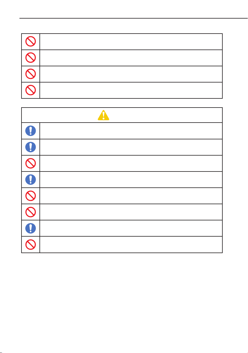
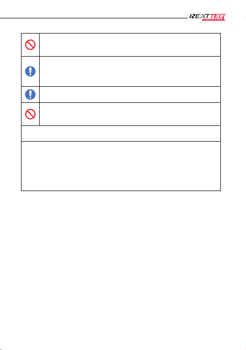
1.1.3 Symbols
In this manual, in addition to the indications “Danger,” “Warning,” and “Caution,” the following symbols
are used to make it easier to understand the content of these warnings.
This symbol indicates a danger that could pose a hazard to someone.
This symbol indicates something that is prohibited and must not occur.
This symbol indicates something that is a necessity and must occur.
6Designed, built and supported by industry professionals for industry professionals.
6
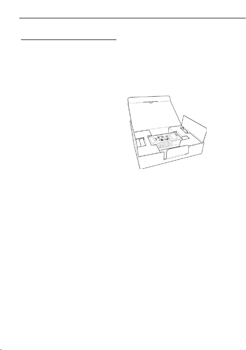
1.2 Checking the Packed Items
After opening the packaging, confirm that all the items have been included. If one of the packed items is
damaged or missing, contact your Nextteq representative. In addition, after opening the packaging, it is
recommended that you store the packing material and box so that you can reuse it in the event that you
request repairs. If you decide to dispose of them however, do so in accordance with your local laws and
regulations, and as indicated by your municipality.
(1) Main unit: 1
(2) AA batteries for checking
operations: 2
(3) Low flow rate orifice: 1
(4) Adapter: 1
(5) Operation manual (this document):1
This product should only be operated by trained and experienced operators that understand the specialized
technology and dangers involved. Untrained or currently-being-trained operators should only
operate the product under close supervision by a person that is already trained or has sufficient specialized
experience.
This operation manual is written assuming the product will be operated by a person that understands the
risks of operating the product.

7
2 SAFETY INSTRUCTIONS
The precautionary information in this operation manual is for ensuring that the product is used safely and
for preventing injury to you and other people and damage to equipment. It is all important for ensuring
safety, so be sure to read it thoroughly before using the product and observe it during use.
DANGER
This product is not explosion proof, so do not use it near combustible or flammable
materials. Doing so could cause explosion or fire.
Do not operate the product near highly flammable or combustible items. Also, do not take in
any gas other than the air. Doing so could cause explosion or fire.
Keep the product away from open flames. Do not burn the product in a fire. Doing so could
cause explosion or fire.
Do not connect to the connector electrode using wire or other metal objects. Doing so could
cause burns, a battery leak, heat generation, or an explosion.
WARNING
Do not expose the product directly to water. Doing so could cause an electric shock or fire.
Do not subject the product to strong impacts or drops. Doing so could cause a malfunction
or accident.
Do not leave the product inside a car in the hot sun, or store it in strong direct sunlight, in
front of heating equipment, or near a fire. Doing so could cause operational problems or a
malfunction.
Do not connect to the connector using wire or other metal objects, or any other method not
specified in this manual. Doing so could cause fire or equipment damage.
Never attempt to disassemble or modify the product. Doing so could cause a malfunction or
accident.
If a problem occurs during operation, immediately stop operating the product, and identify
and eliminate the cause. If it is determined that the product caused the problem, contact your
Nextteq representative or the vendor where you purchased the product.
8Designed, built and supported by industry professionals for industry professionals.
8
Do not cover this product with a cloth or blanket or enclose it inside a box when it is
operating. Doing so could cause heat buildup, a fire or malfunction.
Do not block the exhaust port. Doing so could limit the required flow rate, causing the
internal temperature to rise, leading to a malfunction or fire.
This product is designed for indoor use. Do not use it in an environment in which it will be
exposed to the wind and rain. Doing so could cause a malfunction.
Do not operate this product if it malfunctions, requires repair, or has a cracked or broken
case or other visible or known damage.
CAUTION
If not using the product for an extended period, remove the batteries and store it at a dry, low
temperature location, away from direct sunlight.
Install the product at a level, stable location. Not doing so could cause operational problems
or a malfunction.
Do not place anything on top of the product. Doing so could cause damage to the product
resulting in a malfunction or accident.
When assembling this product, such as when inserting the batteries, be careful that your
fingers do not get pinched.
This product is an air sampling pump. Do not use it for any purpose not indicated in this
manual. Doing so could cause a malfunction.
Do not permit water, other liquids, or non-atmospheric gases to enter the product. Doing so
could cause a malfunction.
Be sure to operate the product with a filter element and sampling unit installed at the intake
port. Sampling air directly for long periods could cause a malfunction.
Do not permit flammable gases, corrosive gases, or chemicals to enter the product. Doing so
could cause a malfunction or fire.
9
Do not insert screws or other foreign objects into the intake port or exhaust port. If a foreign
object accidentally enters the product, immediately switch the power OFF. Then contact your
Nextteq representative or the vendor where you purchased the product.
The normal operating temperature range of this product is 0 to 40˚C, with humidity between
10 and 90 % RH (and no condensation). Operating the product outside these temperature
and humidity ranges could reduce performance, shorten the service life, or cause a
malfunction.
Remove the batteries and disconnect any external batteries before cleaning or inspecting the
product. Not doing so could cause an electric shock, battery leakage, or other problems.
Keep the product away from sources of noise. Also, do not place it in areas with strong
magnetic fields, high dust levels, or high humidity. Doing so could cause product damage or
other problems.
IMPORTANT
Please be aware that in the unlikely event of a product failure, Nextteq International LLC bears no respon-
sibility to compensate for sampling data not acquired or recorded, and is not responsible for loss of data,
or for other direct or indirect damages incurred from such loss. Be sure to back up* data on a regular
basis in case of an accident or failure.
* This product does not have a data output function. To back up the results, you may write them down or
take a photograph.
10 Designed, built and supported by industry professionals for industry professionals.
10
3 ABOUT THIS PRODUCT
3.1 Overview
The personal mini pump NX-300 is a lightweight, portable air sampling pump equipped with functionality
for measuring accumulated flow rates. The flow rate for this pump is 10 mL/min to 300 mL/min, which in
the air sampling pump lineup from Nextteq is a particularly low flow rate range.
It is equipped with a pressure loss correction function and a constant flow rate function. The pump is
controlled so as to maintain the set flow rate even if you are using sampling tubes with different pressure
loss values, or the pressure loss changes during sampling. As a result, this can be used as an air sampling
pump for toxic substances in work environments, indoor environments, and ambient environments.
3.2 Features
A pressure loss correction function is built in, which suppresses intake flow rate fluctuations if
sampling tubes with different pressure loss values are used with the same set flow rate.
A constant flow rate function is built in, which suppresses intake flow rate
fluctuations if a sampling material is used with a pressure loss that changes due to sampling.
An organic EL graphics display has been adopted as the indicator, so you can
check the flow rate information even in a dark location.
The product can run for approx. 10 hours on two alkaline batteries (100 mL/min, unloaded
conditions).
The USB terminal can be connected to a mobile battery* with an output of at least 5 V DC and
500 mA or to an AC adapter for use as an external power supply.
* The product might not operate properly depending on the mobile battery specifications.
NX-300 Constant Flow Range of
10-30 mL/min is a perfect pump for
TWA Nextteq tubes and other low
flow applications.
NX-300 withstands high back pressure –
perfect for use with sorbent tubes.
At 190g (with batteries), 6.70 oz,
the NX-300 is the lightest low flow,
constant flow sampling pump in the
market!
With 10 hours of operation on two
alkaline batteries (100mL/min,
unloaded conditions), provides a full
days’ use with no downtime.
The small size allows one to fit the
NX-300 in a pocket!
W 63 mm – 2.5 in
D 29 mm – 1.1 in
H 115 mm – 4.5 in
Organic Electroluminescent (organic
EL) graphics display allows use in
dark locations.
An operating temperature and hu-
midity range of 0-40˚C (32-104˚F)
and 10-90% RH, makes the NX-300
ideal for almost any application.

11
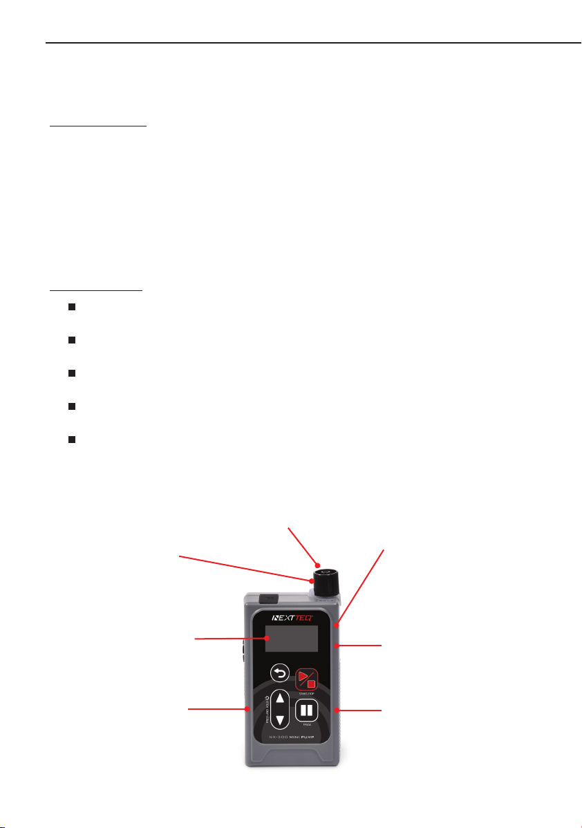
3.3 Names of the Parts
3.3.1 Main Unit
Pump Status and the Color of the Operation Indicator LED (Operating Mode)
Color of the Operation Indicator LED Pump Status (Operating Mode)
Orange During Delay and Manual operation
Green During Run Timer (Run.T) and Interval Timer
operation
Blue During Volume operation
Red During an error
USB Terminal (for external power
supply, Micro B) – allows for extra
sampling time.
Intake port – for use with various
sampling media that requires
constant flow and constant pressure.
Operation indicator LED –
for immediate visual status.
Exhaust port – indented
to protect port to allow for
continuous exhaust.
Battery cover – protects batteries
from harsh environments and allows
rapid change of batteries.
Control panel –
simple design provides
ease of use.
Organic EL
display – for easy
readings in dark
locations.
12 Designed, built and supported by industry professionals for industry professionals.
12
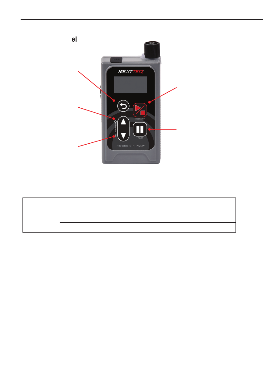
3.3.2 Control Panel
Note
If you press and hold the [BACK] key for 1 second or longer, the system will return
to the [HOME] screen. (If this operation is performed in the setting screen, the
setting details will be lost.)
When changing the setting values, press and hold the [UP] key or [DOWN] key
[START/STOP] Key –
This starts the measurement.
This is for applying the selected
and set items.
[PAUSE] Key –
This pauses the pump operation
[UP] Key and [DOWN] key
simultaneously –
This turns the power ON and
OFF.
[BACK] Key –
This returns to the previous
screen.
[UP] Key –
This is for changing setting
values and for moving to
selected and set items.
[DOWN] Key –
This is for changing setting
values and for moving to
selected and set items.
13
4 OPERATION PROCEDURES
4.1 Preparing the Power Supply and Turning the Pump ON and OFF
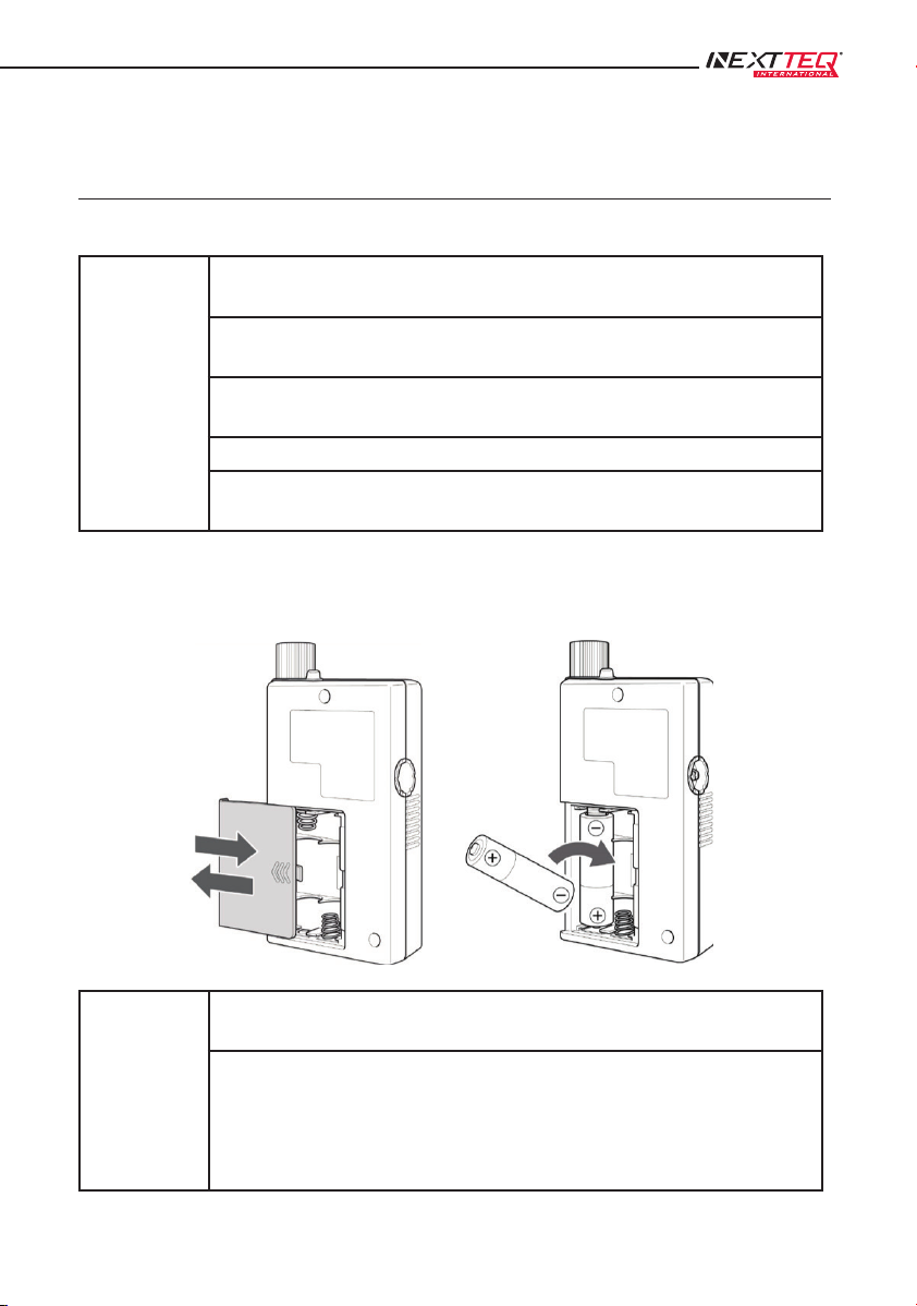
4.1.1 Installing and Removing Batteries
Important
When replacing the batteries, ensure that both of the two batteries are replaced
simultaneously with new ones.
Check the recommended usage time for the batteries and use them before this
time expires.
Be careful not to put the batteries in backwards.
(Do not accidentally reverse the + and - ends.)
Remove the batteries when the product is not in use.
If the batteries leak, the fluid could damage the circuit boards inside the product.
In this case, request repairs or an inspection.
(1) Slide the battery cover and remove it.
(2) Insert two AA batteries (alkaline batteries recommended).
(3) Restore the battery cover.
Note
You can also use rechargeable AA batteries, but limitations will result regarding the
battery level indicator. (Page 15)
If the batteries run out and the power is inadvertently turned OFF, sampling will be
discontinued, and it will not be possible to continue. The discontinued data can be
viewed by selecting “Previous Data” in the main menu. (2 Previous Data). (Page 36)
Note that if you use the pause function, you can replace the batteries and then
continue sampling. (Page 32)

14 Designed, built and supported by industry professionals for industry professionals.
14
NX-300 MINI PUMP
4.1.2 External Power Supply
With this product, you can use an external power supply other than the regular batteries by using the USB
terminal. Note that if a mobile battery is used, ensure that the output is at least 5 V and 500 mA.
Important
Mobile batteries sold for use with smartphones are equipped with a function that
stops the current supply if it drops below a certain value. Accordingly, If the current
value for this product is below the above-mentioned threshold value, the pump may
not operate properly with the mobile battery. It may stop operating for example, or
the power may turn OFF after 10 or 20 seconds.
Note
You can also use an AC adapter with an output of at least 5 V and 500 mA.
If there are batteries in the product when an external power supply is connected, the
external power supply connection will take priority when running it.
In this case, if the power supplied from the external power supply stops, the product
will switch to the power supplied by the internal batteries and it will continue to
operate, thus avoiding problems.
15
4.1.3 Turning the Pump ON and OFF
To turn the power ON or OFF, simultaneously press and hold the [UP] key and [DOWN] key for
approximately 2 seconds. Note that if the power is ON and you are turning it OFF, operation of either the
[UP] key or [DOWN] key will be applied. Continue to press and hold however.
Note
After the power is ON, if you continue to press and hold the [UP] key and [DOWN]
key, the power will turn OFF, after which it will not turn ON.
The product may not operate as per the specifications immediately after the power is
turned ON. Let it warm up (with the pump running) for several minutes before use.
4.1.4 Remaining Battery Level Display
Important
The remaining battery level is displayed at the top right of the screen, but only
during intake. The remaining battery level will not be displayed during setting
changes or other operations, or during standby via timer operation. Also, the
remaining battery level display is designed on the assumption that alkaline batteries
are being used in this product. Rechargeable AA batteries can also be used.
However, because of differences in discharge characteristics, the relationship
between the remaining battery level displayed and the operating time will also differ.
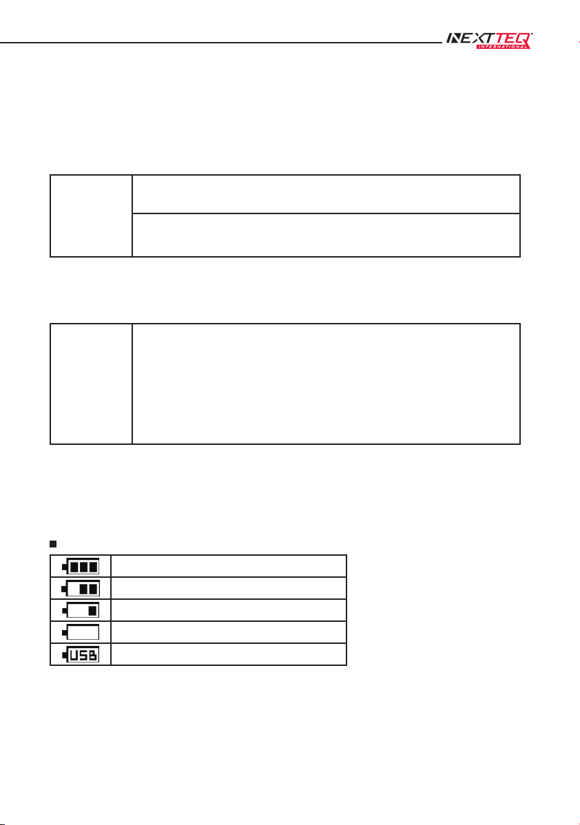
The remaining battery level is displayed as four stages. Note that when power is supplied from the USB
terminal, USB will be displayed in the remaining battery level area and the bar graph will not be displayed.
In this case, check the remaining battery level display on the mobile battery.
Battery Level Display
Over 2.8 V
Between 2.5 V and 2.8 V
Between 2.3 V and 2.5 V
Less than 2.3 V
When power is supplied from the USB terminal

16 Designed, built and supported by industry professionals for industry professionals.
16
Remaining Battery Level Display and Reference Operating Times Until the Pump Stops
(When alkaline batteries are used, and Sleep Mode is set to OFF)
Flow Rate Load
10 mL/min Heat desorption
tube
9 to 10 hours 6 to 9 hours 2.5 to 6 hours
50 mL/min Charcoal tube 5 to 5.5 hours 3.5 to 5 hours 1.5 to 3.5 hours
100 mL/min Charcoal tube 10 to 11 hours 6.5 to 10 hours 2.5 to 6.5 hours
100 mL/min Load equivalent to
20 kPa
5.5 to 6.5 hours 3.5 to 5.5 hours 1.5 to 3.5 hours
200 mL/min Load equivalent to
20 kPa
5 to 5.5 hours 3 to 5 hours 1.5 to 3 hours
300 mL/min Charcoal tube 6 to 7 hours 4 to 6 hours 2 to 4 hours
These values are based on actual measured values under a 25˚C environment. Note that these values
are not guaranteed.
4.2 Pressure Loss
Pressure loss occurs due to sampling tubes or other sampling materials attached
to the intake port. A constant flow rate usage range has been established for this
product (Page 57). If the specified range is exceeded, a malfunction could occur.
However, this product is not equipped with a function to measure pressure loss.
It is recommended that you measure the pressure loss of the sampling material in
advance, as per the figure.
4.3 Using a Micro Impinger
When a micro impinger is used, if the tubing is
connected incorrectly, liquid will inadvertently
be taken into the main unit, resulting in a
malfunction. Accordingly, connect the tubing as
per the figure to the right.
Important As per the figure on the above right, never connect tubing in which liquid is taken in directly.
17
Point with the widest
raised element
Operation indicator
LED
Filter Element
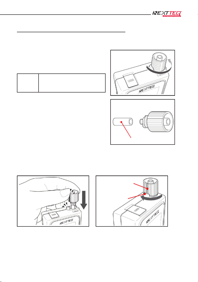
4.4 Attaching and Removing the Intake Port
To remove the intake port, turn it in the counterclockwise direction.
Pull gently on the filter element attached to the
intake port to remove the filter element and then
replace it.
Important
To prevent malfunctions due to the intake
of foreign objects and fine particles, be
sure to attach a filter element.
Match the point on the intake port with the widest raised element* to the operation indicator LED.
Then push the intake port in and turn it 90 degrees in the clockwise direction.
* There are two points on the intake port to serve as positioning guides.

18 Designed, built and supported by industry professionals for industry professionals.
18
Adapter
Sampling tube
Adapter
Low flow rate orifice
Low flow rate orifice adapter
Adapter
Sampling tube
4.5 Using the Low Flow Rate Orifice and Adapter
A low flow rate orifice and adapter are provided with this pump. If you are using the pump with a flow of 50
mL/min or less, attach the low flow rate orifice adapter with the low flow rate orifice connected to the intake
port, and then connect the sampling tube, etc.
Important
When the settings are configured to 50 mL/min or less, if a low flow rate orifice adapter
is not used, the indicated value will not reach the set value or will fluctuate significantly
during operation, so be sure to use it. Note that even if the low flow rate orifice adapter
is used, the pump may operate intermittently depending on the set flow rate and the
load conditions.
When connecting the low flow rate orifice to the adapter, be sure that the arrow on the
low flow rate orifice faces downwards with respect to the adapter.
Note
If the flow rate is set to a value at which the low flow rate
orifice adapter is not used, sampling can be performed with
the sampling tube connected directly to the adapter.
Note that in this case, be very careful not to lose the low flow
rate orifice.
19
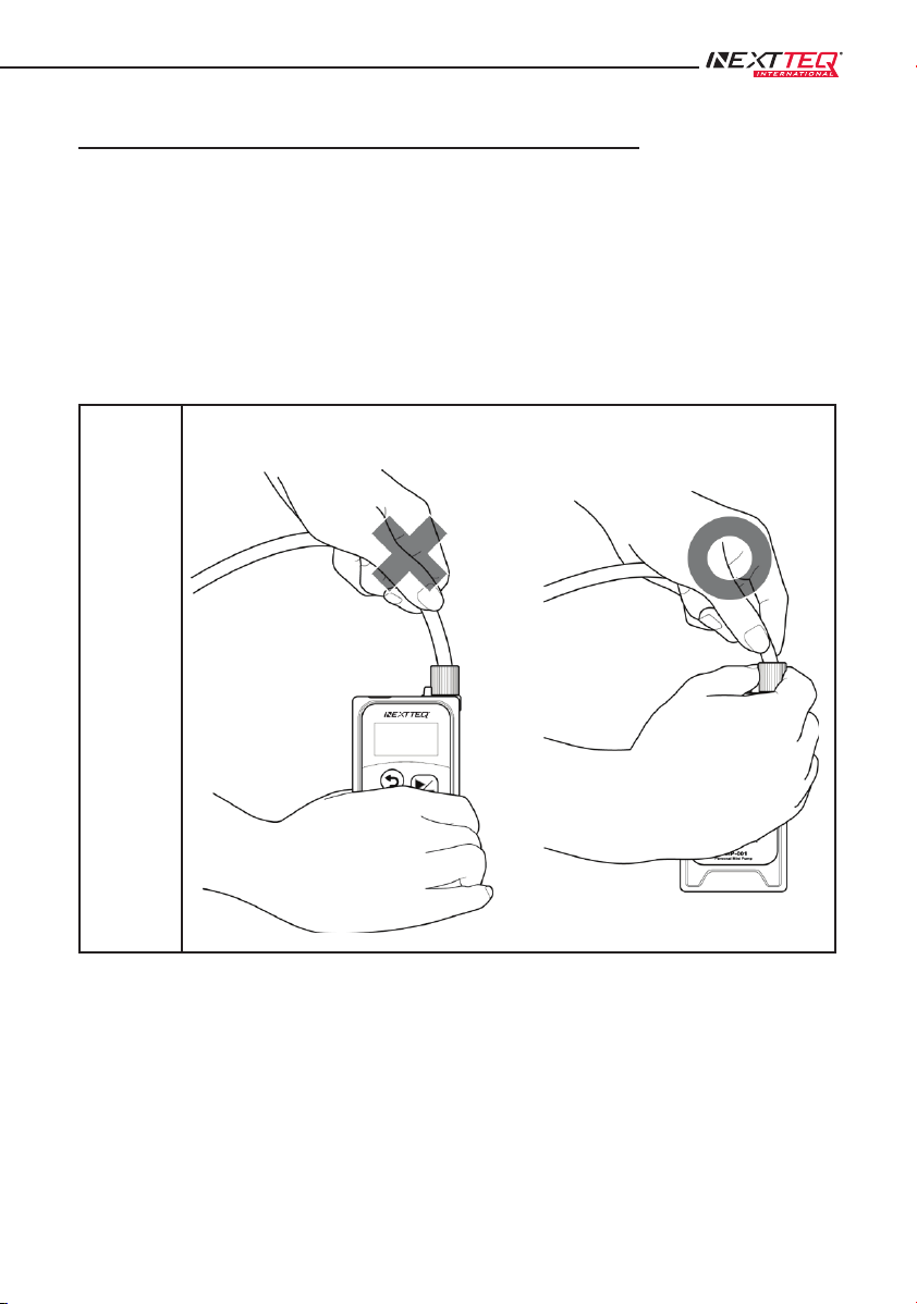
4.6 Installing the Pump and Connecting the Tube
Install this pump on a flat surface. Avoid sites with high humidity, moist sites, sites close to open flames or
heat sources, and sites with extremely high dust levels.
Confirm that the filter element is attached to the intake port. Also, replace the filter element if it becomes
very dirty. (Page 17)
Tubes with an inner diameter of 5 mm or 7 mm can be attached to the intake port.
Important
When removing tubing from the intake port, grip the intake port, not the main unit. There
is a risk that the tube will be damaged if you pull on it with too much force.
20 Designed, built and supported by industry professionals for industry professionals.
20
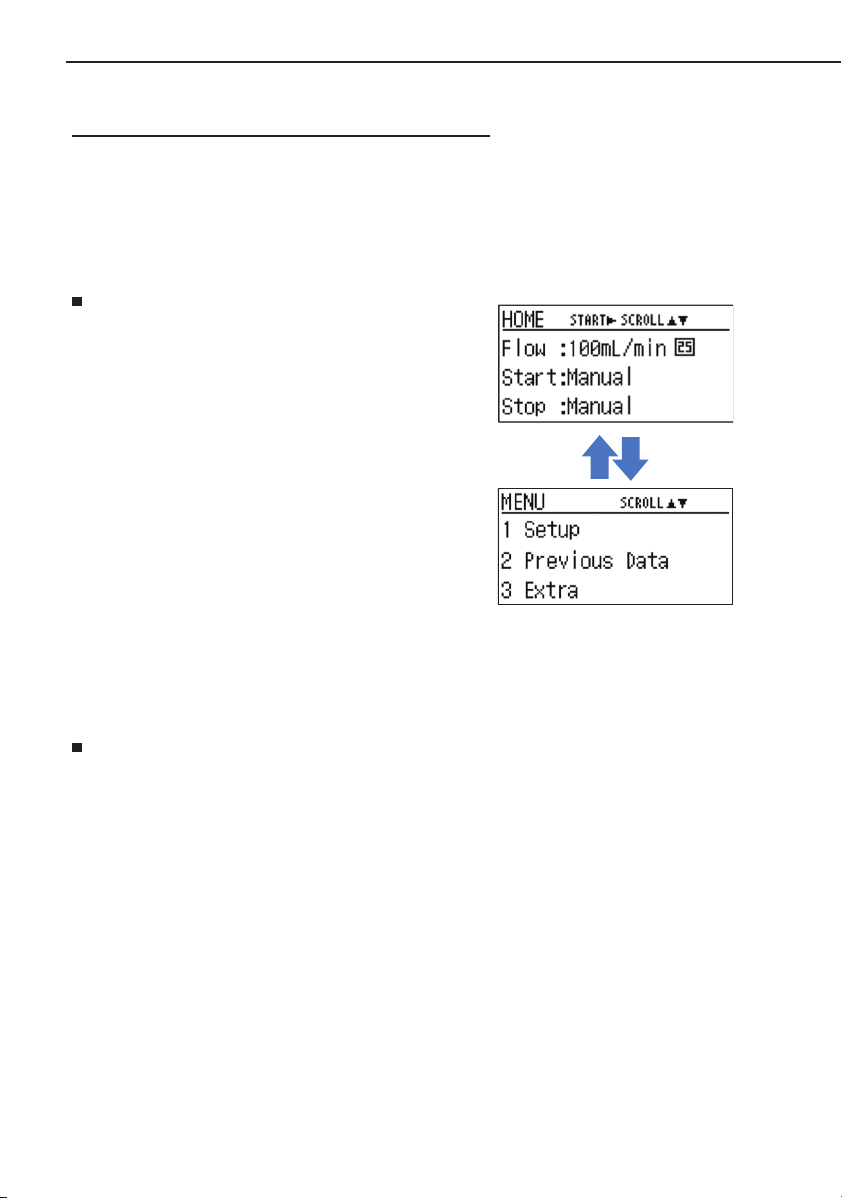
4.7 [HOME] Screen and [MENU] Screen
When the power is turned ON (by pressing and holding the [UP] key and [DOWN] key simultaneously),
the version information will be displayed, and then the system will proceed to the [HOME] screen.
[HOME] Screen
The sampling conditions are displayed.
The key based operations are as follows.
[START/STOP] key
This starts the sampling.
[UP] key or [DOWN] key
This switches to the [MENU] screen.
[MENU] Screen
This screen consists of the following three items.
The selected item will blink.
1 Setup
This is for setting the sampling conditions. (Page 21)
2 Previous Data
This is for checking previous sampling data. (Page 36)
3 Extra
This is for setting various settings other than the sampling conditions. (Page 40)
The key based operations are as follows.
[BACK] key: This switches to the [HOME] screen.
[UP] key or [DOWN] key: This switches the item selected.
[START/STOP] key: This switches to the screen for the item selected.
Table of contents
Other NEXTTEQ Water Pump manuals

Popular Water Pump manuals by other brands


Tuthill
Tuthill AC Installation and service instructions

FLOJET
FLOJET G-57 Series Installation & operation instructions

Miller
Miller JUMBO Operation and maintenance manual

Corken
Corken PT Series Installation, operation & maintenance manual

Ingersoll-Rand
Ingersoll-Rand ARO EVO Series Operator's manual

airbox
airbox VARIFLOW user manual