Thermo Forma 3771 Operating instructions

Millcreek Road, P.O. Box 649
Marietta, Ohio 45750
U.S.A. Telephone: (740) 373-4763
Telefax: (740) 373-4189
Models:
3771 / 3772 3773 / 3774
3775 / 3776 3777 / 3778
3779 / 3780 3785 / 3786
3787 / 3788
Laboratory and Chromatography
Refrigerators
Operating and Maintenance Manual
Manual No. 7003771 Rev. 3
Read this Instruction Manual
Failure to read, understand and follow the instructions in this manual may result in damage to the unit,
injury to operating personnel, and poor equipment performance.
Caution: Any internal adjustments and maintenance must be performed
by qualified service personnel.
51-1483-05 Rev. A
ThermoForma

DoYou Need Information or Assistance on
Thermo Forma Products?
If you do, please contact us 8:00 A.M. to 7:00 P.M. (Eastern Standard Time) at:
1-740-373-4763 Direct
1-888-213-1790 Toll Free, U.S. and Canada
1-740-373-4189 FAX
http://www.forma.com Internet Worldwide Web Home Page
Our Sales Support staff can provide information on pricing and give you quotations. We
can take your order and provide delivery information on major equipment items or make
arrangements to have your local sales representative contact you. Our products are listed on the
Internet and we can be contacted through our Internet home page.
Our Service Support staff can supply technical information about proper setup, operation or
troubleshooting of your equipment. We can fill your needs for spare or replacement parts or pro-
vide you with on-site service. We can also provide you with a quotation on our Extended
Warranty for your Thermo Forma products.
Whatever Thermo Forma products you need or use, we will be happy to discuss your appli-
cations. If you are experiencing technical problems, working together, we will help you locate
the problem and, chances are, correct it yourself... over the telephone without a service call.
When more extensive service is necessary, we will assist you with direct factory trained
technicians or a qualified service organization for on-the-spot repair. If your service need is
covered by the warranty, we will arrange for the unit to be repaired at our expense and to
your satisfaction.
Regardless of your needs, our professional telephone technicians are available to assist you
Monday through Friday from 8:00 a.m. to 7:00 p.m. Eastern Time. Please contact us by tele-
phone or fax. If you wish to write, our mailing address is:
Thermo Forma
Millcreek Road, P.O. Box 649
Marietta, OH 45750
International customers please contact your local Thermo Forma distributor.

SECTION I
General Information

THEMO FORMA MODELS
PART # MODEL # MODEL TYPE CUBIC FEET DOOR TYPE VOLTAGE
52-1996-33 3771 Refrigerator 27.3 1 Glass Hinged 115
52-1996-34 3772 Refrigerator 27.3 1 Glass Hinged 220
52-1996-35 3773 Refrigerator 27.3 1 Solid Hinged 115
52-1996-36 3774 Refrigerator 27.3 1 Solid Hinged 220
52-1996-37 3775 Refrigerator 49.1 2 Glass Hinged 115
52-1996-38 3776 Refrigerator 49.1 2 Glass Hinged 220
52-1996-39 3777 Refrigerator 49.1 2 Solid Hinged 120
52-1996-40 3778 Refrigerator 49.1 2 Solid Hinged 220
52-1996-41 3779 Refrigerator 76.2 3 Glass Hinged 115
52-1996-42 3780 Refrigerator 76.2 3 Glass Hinged 220
52-1996-43 3785 Chromatography 27.3 1 Glass Hinged 115
52-1996-44 3786 Chromatography 27.3 1 Glass Hinged 220
52-1996-45 3787 Chromatography 49.1 2 Glass Hinged 115
52-1996-46 3788 Chromatography 49.1 2 Glass Hinged 220
Except for routine cleaning, these medium tem-
perature cabinets will require little maintenance.
In the unusual event that repair should be neces-
sary, this manual presents information that is
helpful in maintaining, diagnosing, and repairing
these cabinets.

TABLE OF CONTENTS 3
TABLE OF CONTENTS
SECTION I - GENERAL INFORMATION
Handling & Installation ............................................ 5
Condensate Pan Installation .................................... 6
Cabinet Startup ........................................................ 6
Export Models .......................................................... 6
Dimensional Drawings ............................................ 7
Med. Temp., Top Mount, Glass, Pull Door Refrig.
Specifications .......................................................... 8
Med. Temp., Top Mount, Glass, Pull Door Refrig.
Dim. Drawings / Specifications ................................ 9
Med. Temp., Top Mount, Solid, Pull Door Refrig.
Grounding Instructions .......................................... 10
Serial Rating Plates .............................................. 10
COMPONENT IDENTIFICATION
Condensing Unit Assembly Component Ident. ...... 11
Models: 3771 / 3773 / 3777 / 3785 &
Export Models: 3772 / 3774 / 3778 / 3786
Condensing Unit Assembly Component Ident........ 12
Models: 3775 / 3787 &
Export Models: 3776 / 3788
Condensing Unit Assembly Component Ident........ 13
Models: 3779
Export Models: 3780
Evaporator Coil Assembly Component Ident.......... 14
Models: 3771 / 3773 / 3775 / 3777 / 3779 / 3785 / 3787
Export Models: 3772 / 3774 / 3776 / 3778 / 3780 / 3786 / 3788
Evaporator Fan Shroud Assem. Comp. Ident ........ 15
Models: 3775 / 3777 / 3779 / 3787
Export Models: 3776 / 3778 / 3780 / 3788
Electrical Box Assembly Component Ident ............ 16
Models: 3771 / 3773 / 3775 / 3777 / 3779
3787
Export Models: 3772 / 3774 / 3776 / 3778
3780 / 3788
Start Kit Component Ident...................................... 17
Side Light Assembly Component Ident .................. 18
Models: 3771 / 3785 &
Export Models: 3772 / 3786
Mullion Light Fixture Assembly Component Ident.. 19
Models: 3775 / 3779 / 3785 / 3787
Export Models: 3776 / 3780 / 3786 / 3788
SECTION II - ELECTRICAL &
REFRIGERATION INFORMATION
REFRIGERATION SPECIFICATIONS
Med. Temp., Glass & Solid, 1-Door Ref. ................ 23
Models: 3771 / 3773 / 3785 &
Export Models: 3772 / 3774 / 3786
Med. Temp., Glass & Solid, 2-Door Ref. ................ 24
Models: 3775 / 3777 / 3787
Export Models: 3776 / 3778 / 3788
Med. Temp., Glass, 3-Door Ref. ............................ 25
Model: 3779 &
Export Model: 3780
CONTROL ANNUCIATOR PANEL INFORMATION
Control Panel Layout ............................................ 26
General Information / Optional Alarm System ...... 27
Chart Paper Change / Pen Replacement .............. 28
Temp. Recorder Calibration .................................. 29
Battery Backup ...................................................... 29
Alarm/Control Relay .............................................. 29
Set Control Point .................................................... 29
Cobex Model #C-921 ............................................ 30
WIRING DIAGRAMS page .................................. 31
Control Panel page ........................................ 32
Transformer Layout - Export .................................. 33
Temperature Probe Bottle Instructions ....................34

4 TABLE OF CONTENTS
TABLE OF CONTENTS -
continued
SECTION III - MAINTENANCE & REPAIR
General Maintenance & Repair .................................. 37
Service Information ...................................................... 37
Compressor Installation .............................................. 39
COMPONENT REPLACEMENT
Evaporator Drain Pan ............................................ 41
Thermostat ............................................................ 42
Evaporator Fan Motor ............................................ 43
Cam Hinge Doors (Solid Doors Only) .................... 44
Cabinet Center Mullion Heated .............................. 45
Torsion Rod Hinged Doors (Glass Doors Only) .... 46
Door Gasket .......................................................... 47
Metering Device .................................................... 48
Condenser Fan Motor ............................................ 49
Master Power Supply Switch ................................ 50
Light Switch .......................................................... 51
Digital Thermometer Battery Replacement ............ 51
Ballast .................................................................... 52
Fluorescent Bulb .................................................... 53
Touch-up Paint ...................................................... 54
Cleaning ................................................................ 55
TROUBLESHOOTING GUIDES
Machinery .............................................................. 56
Compressor .......................................................... 59
Fluorescent Lamp .................................................. 61
Measuring Starting Lamp Voltage ........................ 63
SECTION IV - PARTS LISTS
Replacement Parts List............................................67
Accessories ............................................................ 69
Lab & Pharmacy Refrigerators/Freezers &
Chromatography Refrigerators Warranty .............. 71
Lab & Pharmacy Refrigerators/Freezers &
Chromatography Refrigerators
International Dealer Warranty ................................ 72
DUE TO CONTINUING PRODUCT IMPROVEMENTS, ALL DATA AND INFORMATION INTHIS MANUAL IS SUBJECT TO CHANGE WITH-

HANDLING & INSTALLATION
GENERAL INFORMATION 5
FREIGHT DAMAGES & SHORTAGES
IMPORTANT
The cabinet was inspected and packaged at the
factory, and should arrive in excellent condition.
The transportation company or other parties
involved in the shipment are responsible for loss
and/or damage. Always make an inspection
before and after uncrating. Inspect the crated
units before locating (preferably at the point of
unloading by the transportation company).
INSPECTING FOR DAMAGES
Note: Always use care when removing shipping
tape, blocks, pads, hardware or other material
until you are satisfied that the unit is completely
operational. Contact Thermo Forma if technical
assistance is required.
Check the cartons or containers.If these are damaged
in any way, open them and inspect the contents in the
driver’s presence. If damage is detected:
1. Have the driver note the nature and extent of the dam-
age on the freight bill.
2. Notify the transportation company at once to request
an inspection. Carrier claim policies usually require
inspections to be made within 15 days of delivery.
3. If damage is noticed, file a claim with the transporta-
tion company.
FILING A CLAIM
File a claim for loss at once with the transportation com-
pany for: A cash adjustment; Repairs; or Replacement.
When filing your claim, retain all packaging materials
and receipts.
HANDLING THE CABINET
Note:
The refrigeration system of the cabinet is
designed to operate with the cabinet located on a level
surface. Do not tilt the cabinet more than 10° to any
side. If the cabinet must be tilted on an angle for han-
dling or moving purposes, allow it to sit in an upright
position 30 minutes prior to starting.
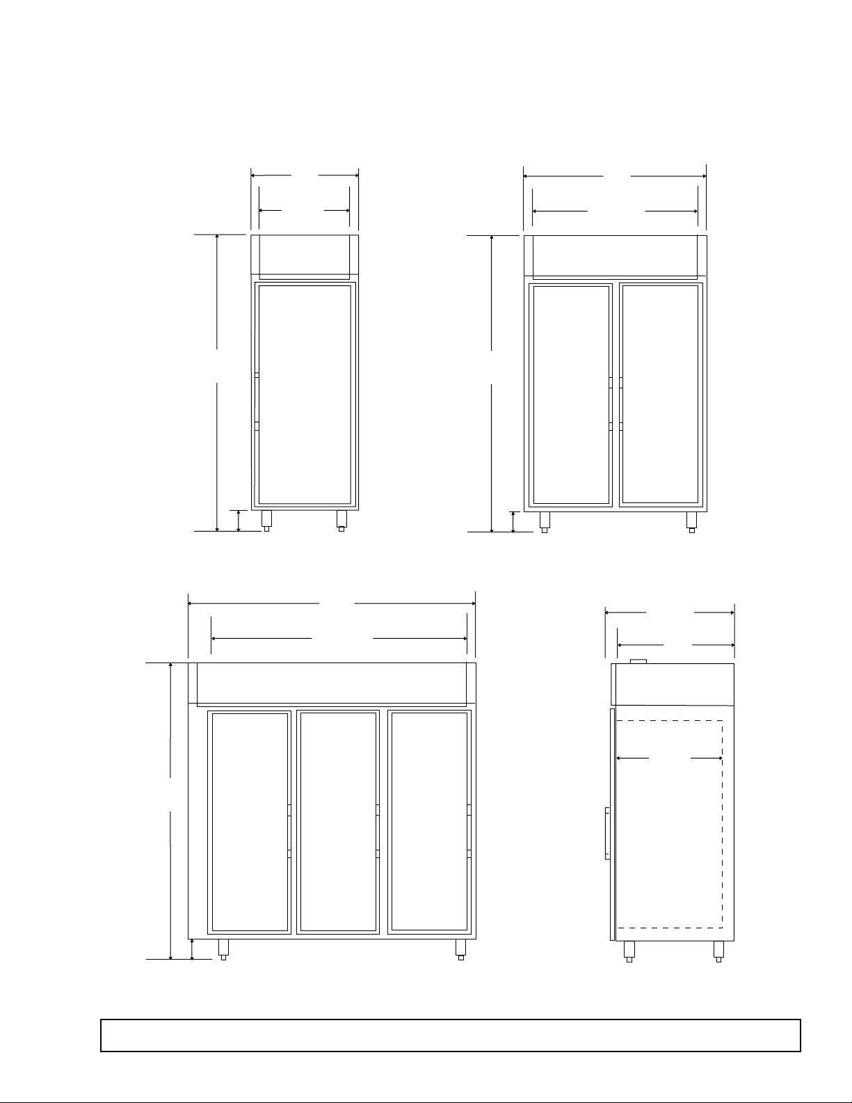
CHOOSING A LOCATION
This model cabinet should be situated to allow proper air
circulation. These cabinets require a 2" minimum clear-
ance behind and 12" between the top of the cabinet and
the ceiling for proper air circulation.
The cabinet must be installed on sturdy, solid, level floor.
The cabinet must be located so it can be plugged into a
properly grounded three-prong electrical outlet of 115
volt, 60 hz.The electrical outlet should not be controlled
by a wall switch which might be turned off accidentally.
UNCRATING THE CABINET
The cabinet should be moved as close as possible to the
operating location before removing crate base. Be sure
to follow the steps in the “INSPECTING FOR DAM-
AGES”instructions.
INSTALLING THE CABINET
(Models with Top Mounted Compressor)
Whenever possible leave the crate base on the cabinet
until it is moved close to the final position.When it is nec-
essary to move the cabinet through a doorway, it may be
necessary to remove the crate base.
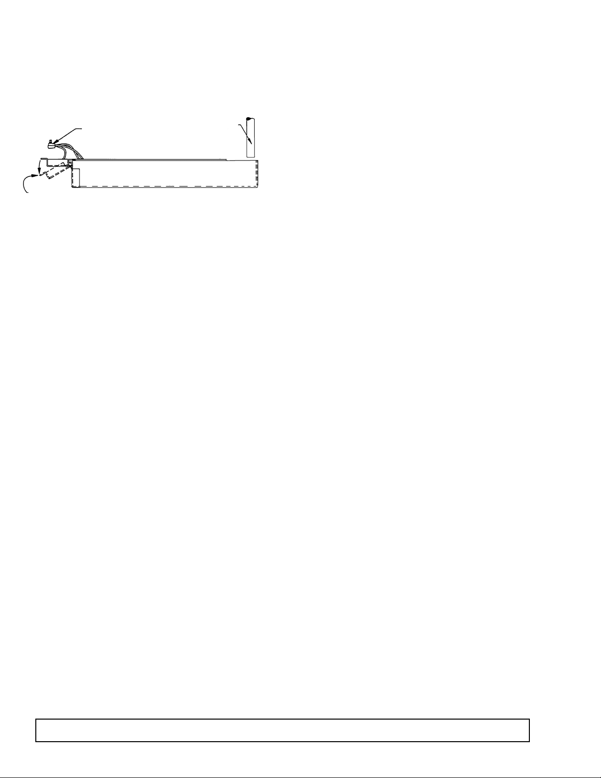
Wood runners are provided on the underside of the cab-
inet for ease in sliding. These runners should be left
attached to the cabinet when the crate base is removed
and should remain attached until after the legs are
installed.The cabinet can then be pushed around more
easily without scratching the floor.The runners also pre-
vent damage to the electrical receptacle and conden-
sate pan hardware on the cabinet bottom.
After the cabinet has been moved to the approximate
final location, remove the package containing the legs
from the cabinet interior. Tape the doors to prevent
accidental opening when handling. Raise the sides of
the cabinet high enough to mount the legs at the loca-
tions provided on the bottom of the cabinet.
IMPORTANT:
AFTER REMOVAL
OF WOOD RUN-
NER, REPLACE
BOLT“A”INTO LEG
MOUNTING
BRACKETS.THIS IS
EXTREMELY
IMPORTANTTO
THE SECURE
ATTACHMENT OF
THE CABINET LEG.
THERE MUST BE
FOUR (4) BOLTS
SECURING EACH
LEG.
Level the cabinet by means of the leg adjustments.
Cabinet doors are self-closing, and the cabinet must be
level to operate properly.

6 GENERAL INFORMATION
CONDENSATE PAN
INSTALLATION INSTRUCTIONS
MAKE SURE THE CABINET IS DISCONNECTED
FROM ITS POWER SOURCE
1. Remove and discard protective cover over electrical
receptacle on bottom of cabinet
2. Bend down front part of housing. (See above.)
3. Insert condensate evaporator pan assembly into the
slide supports on the underside of the cabinet by
pushing toward back of cabinet until it stops.
4. Plug supply cord into receptacle in underside of
cabinet.
5. Bend up front part of housing. Line up slot with
rivnut in cabinet bottom and insert thumbscrew
through slot onto rivnut in cabinet bottom. Insert
thumb screw through slot onto rivnut and tighten.
6.The assembly will now operate when power is sup-
plied to the cabinet.
7. Inspect rear of cabinet to ensure that the drain line
from the evaporator is properly positioned over the
condensate pan.
CABINET STARTUP
Once the cabinet has been located in its permanent
location and the proper power and grounding have
been provided, the following items must be checked or
completed:
1. Cut and remove the compressor hold-down band (if
applicable) so the compressor “floats”freely.
2. Check for traces of oil on the compressor pan which
could mean a broken or leaking refrigeration line.
UNDER NO CIRCUMSTANCE SHOULD THE
COMPRESSOR BE STARTEDWHEN OIL IS PRE-
SENT UNTIL INSPECTED BY A SERVICE TECH-
NICIAN.
3. INSPECT THE FACTORY WIRING FOR
TERMINALS THAT MIGHT HAVE VIBRATED
LOOSE IN SHIPPING. TIGHTEN ALL SCREW-
TYPE TERMINALS.
4. Check the refrigeration lines to see that they are
“free”and no damage was done during shipping.
5. Check fan blade(s) for “free”operation.
6.Turn on the main power switch. Once the compressor
starts, the voltage should be checked at the compres-
sor terminals to determine if there is proper voltage to
the compressor. The voltage should not exceed 10%
above or below the rated compressor voltage.
EXAMPLE: If the voltage reads 115 volts with no load
and it drops below 103 volts when the compressor
starts, it may indicate that the supply wiring is too
small or that the wire run is too long.
7. Make sure that the drain line has not been dis-
lodged or broken during shipping and that the drain
trap terminates properly in the condensate pan or
floor drain. (See Condensate Pan on top mounted
compressor.)
8. Listen for any unusual noise such as lines vibrating,
etc. Correct problem by tightening screws, slightly
bending tubing, etc.
9. Check proper tension on doors. (See Door Torque
Adjustment.)
10. Cabinet should not be loaded with product until
cabinet has operated for 24 hours and reached
desirable storage temperature.
EXPORT MODELS
Export model cabinets come equipped with an auto
transformer located in the unit compartment. The
selector switch can be set to various customer voltage
requirements - Factory Setting: Mid position for an
incoming voltage between 212V and 238V.
PRIOR TO STARTING THE CABINET
Supply voltage must be checked in order to determine
the correct position of the variable voltage switch
located on the auto transformer. This will ensure the
cabinet is operating at the correct optimum voltage. In
the event the transformer supply line plug does not
match the electrical outlet, the plug can be changed to
one with equal voltage-amperage rating.
Refer to page 41 for transformer layout.
DRAIN LINE FROM
EVAPORATOR - SEE
NOTE #7.
SUPPLY CORD

DIMENSIONAL DRAWINGS
MediumTemp.,Top Mount, Glass Pull Door Refrigerators
GENERAL INFORMATION 7
33"
36 1/4"
29 5/8"
SIDE VIEW
31"
26 1/4"
Interior
83 3/4"
6"
83 3/4"
6"
52"
47 1/4"
Interior
83 3/4"
6"
78"
73 1/4"
Interior

8 GENERAL INFORMATION
SPECIFICATION 1-DOOR 2-DOOR 3-DOOR
Compressor Mount Top Top Top
Temperature Range 37°to 55°(3°to 13°C) 37°to 55°(3°to 13°C) 37°to 55°(3°to 13°C)
Number of Doors 1 2 3
Door Construction Double Pane Double Pane Double Pane
Hinge Type Torsion Bar Torsion Bar Torsion Bar
Insulation - CFC-Free Foam-in-Place Urethane Foam-in-Place Urethane Foam-in-Place Urethane
Wall Thickness 2 3/8" 2 3/8" 2 3/8"
Capacity - Gross 27.3 ft.349.1 ft.376.2 ft.3
Shipping Weight (Approx.) 470 lbs. 785 lbs. 1080 lbs.
Compressor Size 1/3 Hp. 1/2 Hp. 1/2 Hp.
Condenser Type Fin & Tube Forced Air Fin & Tube Forced Air Fin & Tube Forced Air
Evaporator Type Fin & Tube Forced Air Fin & Tube Forced Air Fin & Tube Forced Air
Refrigerant Type R404A R404A R404A
Refrigerant Control Expansion Valve Expansion Valve Expansion Valve
Amp Rating - Data Plate 3771: 11.2; 3772: 6.3 3775: 13.8; 3776: 6.1 3779: 16.0; 3780: 8.2
3785: 13.2; 3786: 7.5 3787: 15.8; 3788: 8.8
Electrical Specs.
(V / HZ / PH)
115 / 60 / 1 (Export: 220V/50 Hz) 115 / 60 / 1 (Export: 220V/50 Hz) 115 / 60 / 1 (Export: 220V/50 Hz)
UL & CUL Listed Yes Yes Yes
Interior Finish Powder Coat Finish Powder Coat Finish Powder Coat Finish
Exterior Finish
Lighting
2 Insul. 1500 Milliamp Fluor. Lamps 3 Insul. 1500 Milliamp Fluor. Lamp 4 Insul. 1500 Milliamp Fluor. Lamps
Electrical Information 15 Amp Service Cord 20 Amp Service Cord 20 Amp Service Cord
SPECIFICATIONS
MediumTemp.,Top Mount, Glass Pull Door Refrigerators
MODEL DESIGNATION INFORMATION
NOTE: Export Models use a transformer.
See page 41 for information on how to set transformer during installation.
1-DOOR:
3771
3785
EXPORT MODELS:
3772
3786
2-DOOR:
3775
3787
EXPORT MODELS:
3776
3788
3-DOOR:
3779
EXPORT MODELS:
3780

GENERAL INFORMATION 9
SPECIFICATION 1-DOOR 2-DOOR
Compressor Mount Top Top
Temperature Range 37°to 55°(3°to 13°C) 37°to 55°(3°to 13°C))
Number of Doors 1 2
Door Construction Foam-in-Place Foam-in-Place
Hinge Type Camlift / Spring Assist Camlift / Spring Assist
Insulation - CFC-Free Foam-in-Place Urethane Foam-in-Place Urethane
Wall Thickness 2 3/8" 2 3/8"
Capacity - Gross 27.3 ft.349.1 ft.3
Shipping Weight (Approx.) 440 lbs. 604 lbs.
Compressor Size 1/3 Hp. 1/3 Hp.
Condenser Type Fin & Tube Forced Air Fin & Tube Forced Air
Evaporator Type Fin & Tube Forced Air Fin & Tube Forced Air
Refrigerant Type R404A R404A
Refrigerant Control Cap Tube Cap Tube
Amp Rating (Data Plate) 3773: 8.9; 3774: 5.2 3777: 8.9; 3778: 5.2
Electrical Specs.
(V / HZ / PH)
115 / 60 / 1 115 / 60 / 1
UL & CUL Listed Yes Yes
Interior Finish Powder Coat Finish Powder Coat Finish
Exterior Finish
Compressor Make Americold Americold
Electrical Information 15 Amp Service Cord 15 Amp Service Cord
SPECIFICATIONS
MediumTemp.,Top Mount, Solid Pull Door Refrigerators
MODEL
DESIGNATION
INFORMATION
NOTE: Export Models use a
transformer. See page 41 for
information on how to set
transformer during installa-
tion.
1-DOOR:
3773
EXPORT MODEL:
3774
2-DOOR:
3777
EXPORT MODEL:
3778
33"
34 3/4"
29 5/8"
SIDE VIEW
31"
26 1/4"
Interior
83 3/4"
6"
83 3/4"
6"
52"
47 1/4"
Interior
36 9/16"
DIMENSIONAL DRAWINGS
MediumTemp.,
Top Mount,
Solid Pull Door
Refrigerators

10 GENERAL INFORMATION
SERIAL RATING PLATES
Serial Number Rating Plates on each vertical cabinet are located on the inside upper left hand corner.This plate
contains all technical data necessary to the operation of the cabinet.(Sample below.) Warranty administration is
based on the serial number as printed on the rating plate.
GROUNDING INSTRUCTIONS
This appliance is equipped with a three-prong
(grounding) plug for your protection against shock
hazards.The appliance should be plugged directly into
a properly grounded three-prong receptacle.
Where a two-prong wall receptacle is encountered, it
must be replaced with a properly grounded three
prong receptacle in accordance with the National
Electrical Code and local codes and ordinances. The
work must be done by a licensed electrician.
IMPORTANT
Do not under any circumstances cut or remove the
round grounding prong from the equipment plug.
WARNING
Consult a licensed electrician if you have any
doubt about the grounding of your wall recepta-
cle.Only a licensed electrician can determine the
polarization of your wall receptacle. Only a prop-
erly installed three-pronged wall receptacle
assures the proper polarization with the equip-
ment plug.
MODEL SER.
REFRIGERANT VOLTS
TYPE # WIRES PHASE HERTZ
CHARGE TOTAL AMPS MAXIMUM
DESIGN MINIMUM FUSE SIZE
PRESSURE (PSIG) REFRIG. DEFROST LOCKED CIRCUIT OR HACR TYPE
HIGHSIDE CYCLE CYCLE ROTOR AMPACITY CIRCUIT
LOWSIDE
BREAKER
WH
G
RATING: 115V, AC 15 Amp
Plug
5-15 Receptacle
5-15R
RATING: 125V, AC 20 Amp
Plug
FLAMMABLE MATERIAL STORAGE
To meet the requirements for storing flammable material, cabinet has no opening other than
the door, or any electrical components below compressor compartment.
DO NOT MODIFY CABINET OR REMOVE LABEL ON THE FRONT WHICH SPECIFIES STORAGE LIMITS!!

GENERAL INFORMATION 11
CONDENSING UNIT ASSEMBLY Component Identification
Models: 3771 / 3772 / 3785 / 3786 50-0142-*
Models: 3773 / 3774 / 3777 / 3778
50-0141-*

12 GENERAL INFORMATION
CONDENSING UNIT ASSEMBLY Component Identification
Models: 3775 / 3787
Export Models: 3776 / 3788
NOTE: See Parts Section IV.

GENERAL INFORMATION 13
CONDENSING UNIT ASSEMBLY Component Identification
Models: 3779
Export Models: 3780

14 GENERAL INFORMATION
EVAPORATOR COIL ASSEMBLY Component Identification
Models: 3771 / 3773 / 3775 / 3777 / 3779 / 3785 / 3787
Export Models: 3772 / 3774 / 3776 / 3778 / 3780 / 3786 / 3788
ITEM DESCRIPTION
1 Coil, Evaporator
Coil, Evaporator
2 Expansion Valve
3 Copper Tubing, 1/4
4 Copper Tubing, 1/2
5 Wire Tie, Nylon
9 Brazing Alloy
Note: Glass models shown.
Solid door models captube replacedT.X.V..

GENERAL INFORMATION 15
EVAPORATOR FAN SHROUD ASSEMBLY Component Identification
Models: 3771 / 3773 / 3775 / 3777 / 3779 / 3785 / 3787
Export Models: 3772 / 3774 / 3776 / 3778 / 3780 / 3786 / 3788
SEQ DESCRIPTION
10 MOTOR
20 FAN BLADE
30 FAN GUARD
40 SCREW
50 STAR WASHER
60 SHROUD, FAN
70 SCREW
80 WASHER
90 SCREW
100 HEX NUT
110 GROUND LEAD
120 HARNESS, DRAIN HEATER
130 STRAIN RELIEF
140 FAN HARNESS
150 CORD CLIP
160 WIRE TIE
170 BRACKET, HANGER DRAIN PAN
GROUND LEAD DETAIL
TYPICAL 2 PLACES FAN MOUNTING DETAIL
INSTALL FAN BLADE WITH HUB
TOWARD MOTOR LOCATED TO
DIMENSION SHOWN.

16 GENERAL INFORMATION
ELECTRICAL BOX ASSEMBLY Component Identification
Models: 3771 / 3773 / 3775 / 3777 / 3779 / 3785 / 3787
Export Models: 3772 / 3774 / 3776 / 3778 / 3780 / 3786 / 3788

GENERAL INFORMATION 17
START KIT Component Identification
If applicable

18 GENERAL INFORMATION
SIDE LIGHT ASSEMBLY
Models: 3771 / 3785
Export Models: 3772 / 3786
ITEM DESCRIPTION
1 Lamp Bracket LH
2 Lampgolder - Top
3 Lampholder - Bottom
This manual suits for next models
13
Table of contents