Thermofilm THH1500A User manual

R A D I A N T O U T D O O R H E A T E R S
OPERATION, INSTALLATION AND MAINTENANCE MANUAL
Flush Mount Enclosur e
The heater that is a design f e a ture!

2
R A D I A N T O U T D O O R H E A T E R S
Mounting options
The installation of HEATSTRIP
®
Classic is simple and easy with the standard mounting rackets supplied. For other more
challenging locations there are range of mounting options availa le - refer to elow diagrams.
The HEATSTRIP
®
Classic can e mounted directly to the ceiling, angled downwards on a wall, fitted flush with the ceiling;
suspended on chains or poles; attached to eams or poles; mounted end-to-end, or 2 units together. Refer to the following
pages for more detailed information on each mounting option.
STANDARD MOUNTING BRACKETS
INCLUDED IN BOX
FLUSH MOUNT ENCLOSURE
EXTENSION MOUNT KIT WITH POLES
TWIN MOUNT BRACKET
SUSPENSION MOUNT BRACKET
END TO END MOUNTING BRACKET
POLE/BEAM MOUNT BRACKET
STANDARD
BRACKET BEAM/POLE
MOUNT
BRACKET
FLUSH
MOUNT
ENCLOSURE
EXTENSION
MOUNT
BRACKET
SUSPENSION
MOUNT
BRACKET
Ceiling
TWIN MOUNT
BRACKET
3
R A D I A N T O U T D O O R H E A T E R S
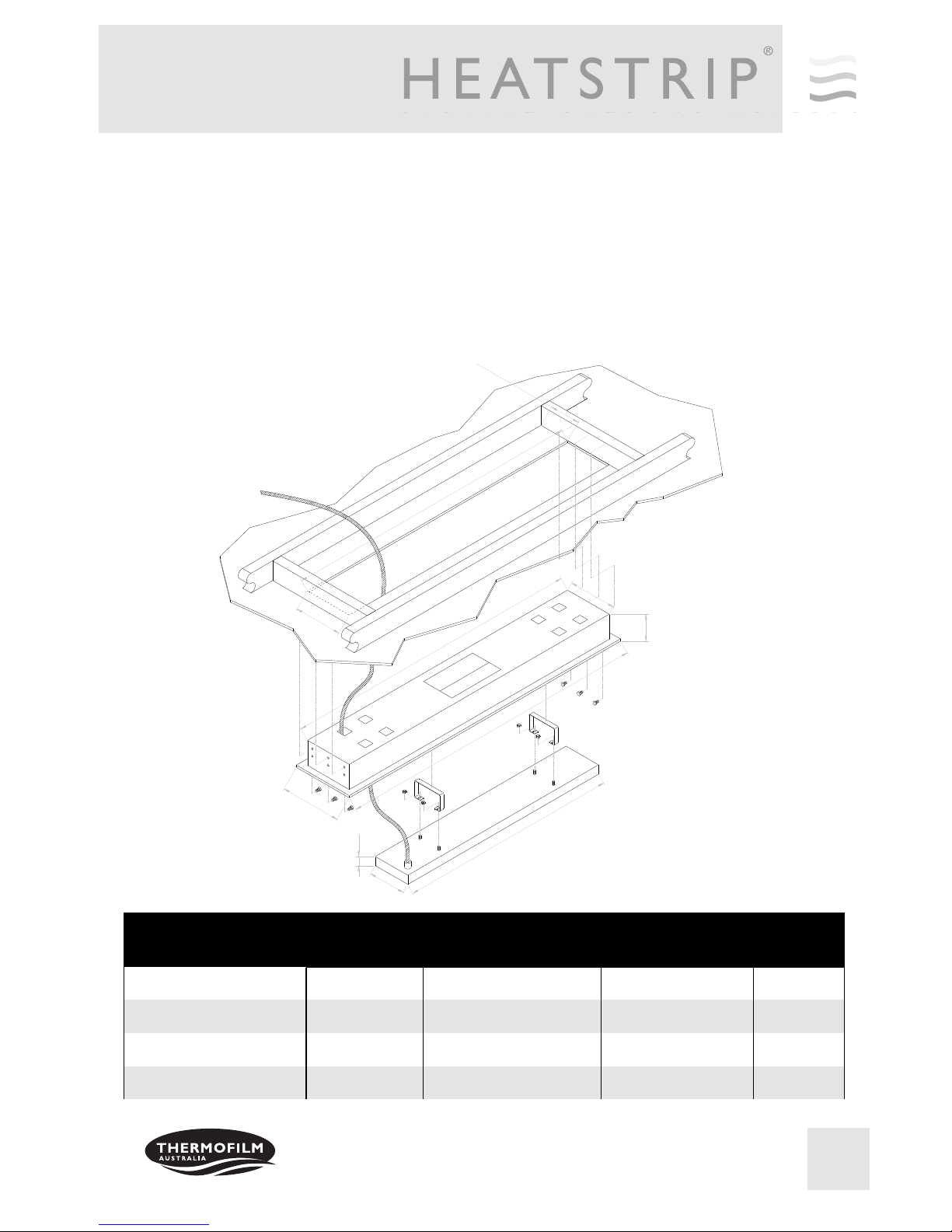
Flush mount enclosure
The Flush Mount Enclosure is an ideal way to neatly install the HEATSTRIP
®
into a ceiling. They are availa le for
all HEATSTRIP
®
Classic models, and are supplied as a one-piece unit for mounting of heaters. Flush mounting
can e used with plaster or wood lined ceiling materials.
An ideal mounting height is 2.5m-2.7m, with a maximum ceiling height of 3.0m in an outdoor enclosed environment.
Maximum mounting heights should e strictly followed, otherwise the performance of the units may e reduced.
The facia of the enclosure is manufactured from 316 Stainless Steel and the rear casing is lack zinc coated steel.
Please refer to the Installation Manual for more detailed installation information.
42
172
1330
125
1412
1470
221
1420
230
280
SUITA LE FOR
MODELS
HOLE CUTOUT
DIMENSIONS (mm)
OVERALL
DIMENSIONS (mm)
WEIGHT
(kg)
THH1800A 1160 x 230 1210 x 280 x 125 6
THH2400A 1420 x 230 1470 x 280 x 125 8
THH3200A 1830 x 230 1880 x 280 x 125 9
PART No
THHAC-010
THHAC-011
THHAC-012
THH1500A THHAC-009 980 x 230 1030 x 280 x 125 5.5

4
R A D I A N T O U T D O O R H E A T E R S
FME DIMENSIONS
VIEW FROM UNDERNEATH
VIEW FROM TOP
MODEL “A” (mm) “B” (mm) “C” (mm)
THH1500A 1030 974 970
THH1800A 1210 1154 1150
THH2400A 1470 1414 1410
THH3200A 1880 1824 1820
PART No
THHAC-009
THHAC-010
THHAC-011
THHAC-012
280
220
Ø8
170
35
125
10
226
280
55
"A"
"B"
"C"
5
R A D I A N T O U T D O O R H E A T E R S
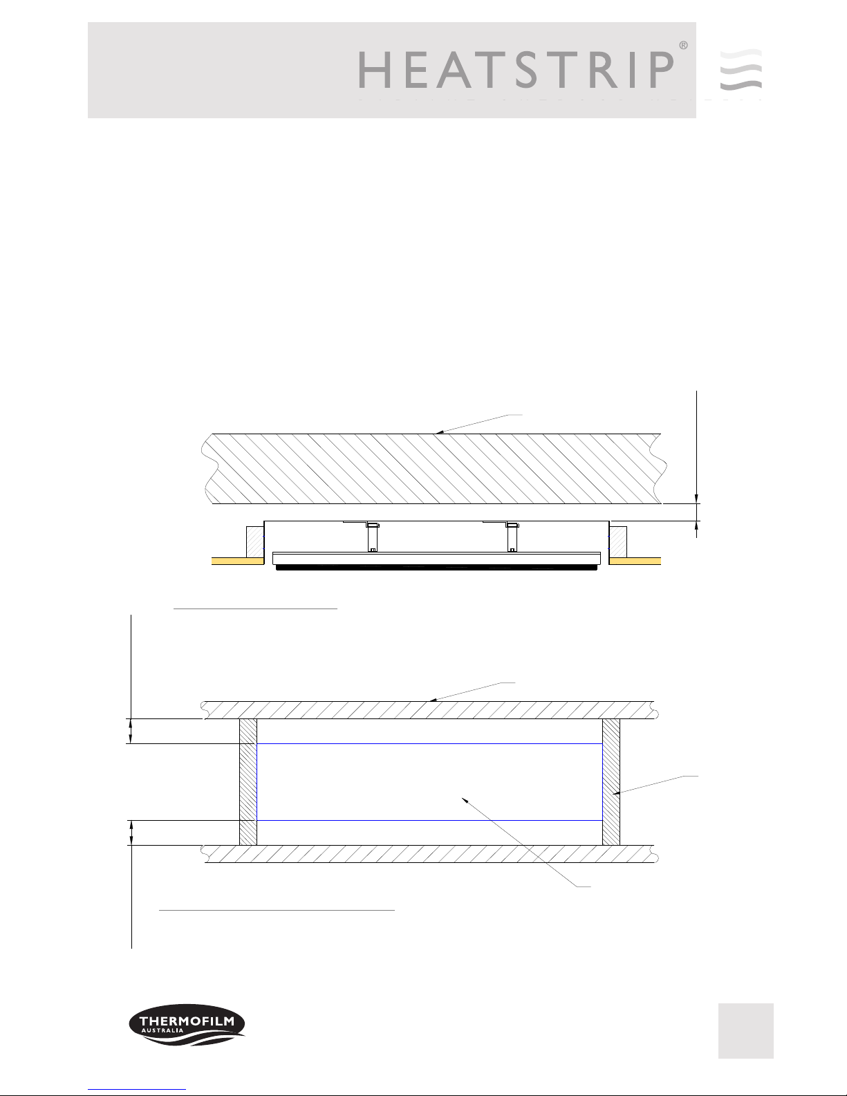
50mm MINIMUM
VIEW FROM ABOVE UNIT
50mm MINIMUM 50mm MINIMUM
CEILING JOIST
BATTEN
FLUSH MOUNT ENCLOSURE
ROOFING MATERIAL
VIEW FROM SIDE
INSTALLATION CLEARANCE DIMENSIONS
S own in t e diagrams below are t e minimum clearance required for t e installation of t e Flus Mount En-
closure.
It is imperative t at all cables, backing materials, insulation and ot er materials are keep clear of t e back and
t e sides of t e Flus Mount Enclosure.
6
R A D I A N T O U T D O O R H E A T E R S
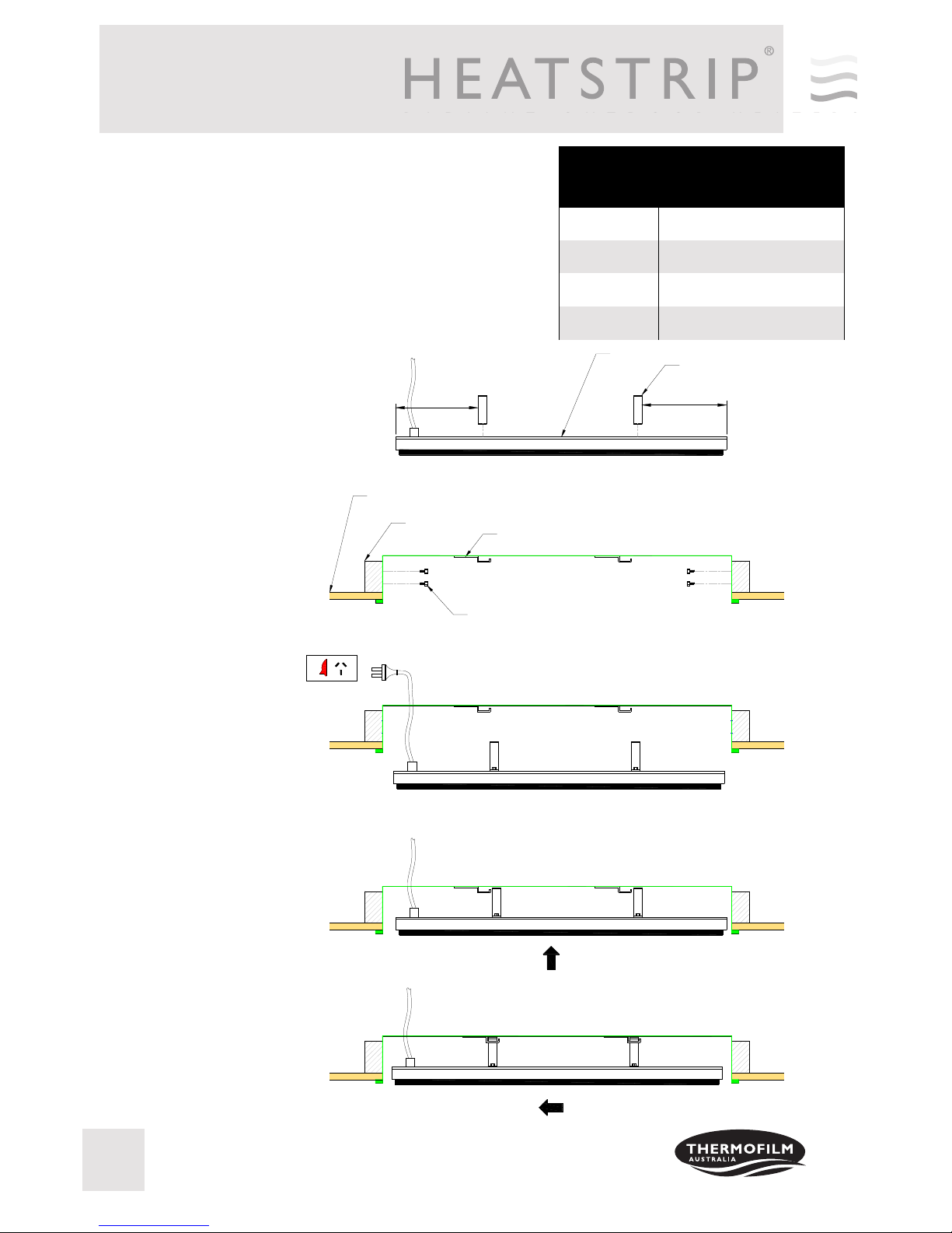
INSTALLATION
INSTRUCTIONS
Ensure all minimum clearance requirements are met and t e materi-
als used are compliant to your local building codes.
Before installing t e FME, ensure t e site to be fixed is fully pre-
pared wit t e ole cut t e correct size and t e mounting points se-
curely in place.
STEP 1: Attac t e
brackets to t e rear of
t e eater. T e dimen-
sions for t e spacing of
t e brackets is listed in
t e table.
STEP 2: Screw t e
FME into t e battens.
NOTE: screws are not
included.
STEP 3: If t ere is no
roof access, connect t e
eater to t e power
source, ensure t e
power is OFF.
STEP 4: Lift t e eater
into t e FME ensuring
t e brackets are to t e
side of t e mounts
STEP 5: Pus t e
eater to t e left ensur-
ing t e brackets engage
in t e mounts. It will
t en drop in. S ake t e
eater to ensure t at it
is securely mounted.
MODEL “D”
DISTANCE FROM END
TO RACKET (mm)
THH1500A 150
THH1800A 240
THH2400A 370
THH3200A 425
HEATER
BRACKET x2
FLUSH MOUNT ENCLOSURE
TIMBER BATTEN
PLASTER CEILING
SCREWS, AT EACH END, THERE ARE 6 HOLES
WITH A DIAMETER OF 8mm EACH
ON
OFF
"D"
"D"

7
R A D I A N T O U T D O O R H E A T E R S
SAFETY
In operation, t is eater is VERY HOT— do not touc any part of t e eater w ile it is turned on. Do not touc
any part until 30 minutes after it is turned off.
T is appliance is not intended for use by persons (including c ildren) wit reduced p ysical, sensory or intel-
lectual capabilities, or lack of experience and knowledge, unless t ey ave been given supervision or instruc-
tion concerning use of t e appliance by a person responsible for t eir safety. C ildren s ould be supervised to
ensure t ey do not play wit t e appliance.
Do not allow any cables, furnis ings, flammable materials or ot er items come in contact wit any surface of
t e Flus Mount Enclosure.
If installed in wet areas, t e eater switc es or controls must be located so t at t ey cannot be touc ed by per-
sons in t e bat or s ower.
T e Flus Mount Enclosure needs to be installed as per t e installation instructions paying special attention to
t e minimum clearances. T e eater needs to be mounted on a rigid bracket or fixing.
See t e eater Operations, Installation and Maintenance Manual for t e eater specific guidelines.
MAINTENANCE
T e Flus Mount Enclosure is made from durable materials, owever regular care and maintenance of your
product will elp prolong its life.
It is recommended t at you wipe down your Flus Mount Enclosure and wit a soft clot gently wipe t e sur-
faces of t e FME wit a mild detergent to remove t e built up contaminants from t e environment. T en wit a
clean clot ensure all detergent is removed.
All c emicals in t e atmosp ere including cigarette smoke, pollution etc. will tarnis t e surface of t e Flus
Mount Enclosure. In t is case, additional cleaning and maintenance may be required. T e cleaning process at
least every t ree mont s will reduce t e amount of build up and keep it looking as best it can. If t e Flus
Mount Enclosure is in a corrosive environment eg. salt spray, we recommend t at you clean t e FME every
week.
Before cleanings or inspection activity, t e eater must be switc ed off and cooled down completely.
Do not use any abrasive materials or products to clean t e Flus Mount Enclosure, t is includes solvents, citrus
based cleaners or ot er ars cleaning products.
W en andling t e Flus Mount Enclosure, ensure t at your ands are clean or t at you use clean gloves as
grease or dirt can mark t e surface of t e eater.
Do not use ig pressure water to clean Flus Mount Enclosure. It is not recommended to ose down t e FME
and eater as water may get into t e roof cavity.

8
R A D I A N T O U T D O O R H E A T E R S
WARRANTY TERMS & CONDITIONS
T e below Warranty Terms and Conditions apply for New Zealand and Australia onl . For international warranty please
refer to international warranty terms and conditions.
T ermofilm warrants to t e original owner t at t e FLUSH MOUNT ENCLOSURE product will be free from defects in
materials and workmans ip for a period of 12 mont s from t e date of purc ase in accordance wit t e following warranty
terms and conditions.
Provision of t is warranty is subject to:
• T e HEATSTRIP
®
FME product must be installed in accordance wit t e Installation Instructions and relevant
electrical standards and codes.
• T e HEATSTRIP
®
FME product must be maintained and cleaned according to instructions detailed in t e
Installation Manual.
• T ere is no warranty expressed or implied wit regard to capacity requirements. T e selection of t e unit or
units depends entirely upon t e system design and capacities as determined by t e purc aser.
• T e customer as not repaired, opened or altered t e product in any unaut orised manner.
• T is warranty excludes damage to t e product or components arising from circumstances outside t e control of
T ermofilm, including, but not limited to, w ere t e product is not used for intended purpose; w ere t e prod-
uct as been rectified in any way; incorrect installation; incorrect power supply; damaged caused during deliv-
ery; misapplication, misuse, abuse, vandalism, lack of maintenance or accident.
• T ermofilm’s obligations under t is warranty are limited to repair or replacement at T ermofilm’s factory of
any components of t e product w ic T ermofilm identifies to its satisfaction to be defective.
• Transportation c arges involved in return of t e product to t e T ermofilm factory (or any ot er location
aut orised in writing by T ermofilm) is t e sole responsibility of t e customer.
• All products are inspected and tested before despatc and are at t e risk of t e purc aser after t e s ipment
from t e T ermofilm factory, if not delivered by T ermofilm to destination.
• Discolouration of t e surface may occur after a period of time, t is does not constitute a warrantable event.
• No products or components will be supplied in advance of an examination of t e faulty product or components
by T ermofilm or an aut orized representative of T ermofilm.
• T ermofilm does not participate in any site related costs or labour expenses incidental to replacement of parts,
repairing, removing, installing, servicing, transportation or andling of parts to complete products, and as-
sumes no liability on parts repaired or replaced wit out written aut orisation. T ermofilm s all not be liable
for any default or delay in performance of its warranty obligations caused by any circumstances beyond its
control, including, but not limited to, judicial or government restrictions, strikes, fires, floods, abnormal
weat er conditions, delayed supply of components.
S ould products be determined as damaged on arrival, immediately notify t e transport company of t e condition and ave
t em noted on t e freig t documents. If damage is discovered after unpacking, demand immediate inspection by t e trans-
portation company and insist t at a record of t e damage is made on t e freig t documentation.
T e customer warrants using t e product in accordance wit :
• Any instructions provided to it by T ermofilm from time to time.
• All government and local regulations, including but not limited to all relevant electrical, environmental laws
and regulations governing t e installation, storage, use, andling and maintenance of t e goods.
• All necessary and appropriate precautions and safety measures relating to t e installation, storage, use, an-
dling and maintenance of goods.
Our goods come with guarantees that cannot be excluded under the Australian Consumer Law. You are entitled to a replacement or re-
fund for a major failure and for compensation for any other reasonably foreseeable loss or damage. You are also entitled to have the
goods repaired or replaced if the goods fail to be of acceptable uality and the failure does not amount to a major failure.
All warranty requests for repairs or replacements must be accompanied by a complete “Warranty Claim Form” available
from T ermofilm, toget er wit proof of purc ase (and w ere possible, p otos of t e installation) and t e eater returned to
t e place of purc ase.
In t e event of a warranty claim, t e goods need to be returned to t e distributor/retailer for repair/replacement. Contact
T ermofilm Australia Pty Ltd
27 Rosalie Street, Springvale, Victoria 3171, Australia
Telep one: (03) 9562 3455,
Email: info@t ermofilm.com.au
This manual suits for next models
7
Table of contents
Other Thermofilm Enclosure manuals


