Thermsaver White Cased Oil Boiler User manual
Installation
&
Users Guide
OIL HEATING SOLUTIONS
White Cased Oil Boiler

1
Page
INTRODUCTION 2
USER INSTRUCTIONS 3
- BOILER OPERATION 3
- SWITCHING THE BOILER ON 3
- BOILER CONTROLS 4
- SWITCHING THE BOILER OFF 5
- BURNER LOCKOUT 5
- RESTARTING AFTER LOCKOUT 5
- RESTART 6
INSTALLATION
- REGULATIONS 7
- WATER CONNECTIONS 7
- BOILER LOCATION 8
- CONVENTIONAL FLUE INSTALLATION 9
- BALANCED FLUE INSTALLATION 10-18
- CONNECTING OIL SUPPLY 18-19
- ELECTRICAL CONNECTION/WIRING DIAGRAM 20
TECHNICAL DATA
- BOILER SPECIFICATIONS 21
- COMMISSIONING INSTRUCTIONS 22
- SERVICING INSTRUCTIONS 22
- FAULT FINDING 23
- PARTS LIST 24
- BURNER SETTINGS 25
Issue No.1 1/6/04

INTRODUCTION
Thank you for choosing the THERMSAVER oil boiler, please read the following carefully.
To the installer
This manual must be left with the householder by the installer who will instruct the user on
the boiler operation.
To the user
Please read the user section of this manual to familiarize yourself with the boiler operation.
WARRANTY WARRANTY FOR YOUR BOILER MUST MEET THE FOLLOWING
CONDITIONS OR YOUR WARRANTY MAY BE INVALID
Warranty on the Heat Exchanger: 5 Years
Warranty on Burner and Controls: 2 years
CONDITIONS OF WARRANTY:
1.Boiler MUST BE installed by an OFTEC registered engineer ,if not permission will be
required by building control.
2.Boiler MUST BE commissioned after installation by an OFTEC registered engineer.
3.Boiler MUST BE serviced every 12 months after installation by an OFTEC registered
engineer.
4.Installer MUST COMPLETE an Installation/Commissioning Form, which will be found
along with your manual and this must then be returned to the address on the warranty
form. Failure to return this form, may invalidate your warranty.
2

USER INSTRUCTIONS
3
BOILER OPERATION
The Boiler Control Thermostat responds to the temperature of the water within the boiler
and switches power to the burner when heat is required.
The burner has an independent control system which regulates the firing and (shut-off)
of the burner.
Automatic firing of the burner will occur when the water temperature within the boiler
falls below the control thermostat set point which will continue to run until the water
temperature rises to the temperature (recommended) set on the boiler control
thermostat.
SWITCHING THE BOILER ON
- Check there is water in the system.
- Check radiator valves are on.
- Turn on oil supply.
- Switch electrical supply to the boiler on (including time clock ) and then set the boiler
control thermostat to recommended setting.

BOILER CONTROLS
BOILER CONTROL THERMOSTAT
The temperature of the water within the boiler is controlled and maintained by the Boiler
Control Thermostat located on the boiler control panel.
TEMPERATURE SETTINGS:
The Boiler Control Thermostat has a range of 50˚C to 80˚C. The recommended setting for
the boiler control thermostat is:
WINTER
Heating and hot water supply 80˚C
SUMMER
Domestic hot water supply 65˚C
It is not recommended to operate the boiler with a thermostat setting of less than 60˚C,
as this will precipitate corrosion, thus reducing the life of the boiler.
MAINS INDICATOR: GREEN
The mains indicator will illuminate when the mains supply to the boiler is on.
HIGH LIMIT STAT INDICATOR: ORANGE
The high limit lockout will illuminate when the water within the boiler is or has overheated
e.g. reached a temperature above that set on the high limit thermostat.
This indicates that the thermostat needs to be reset.
TO RESET THE BOILER
When the boiler has had time to cool, the manual reset button (coloured red) on the
control panel will need to be pressed in to reset. If the high limit thermostat continues to
trip, contact your installer as there may be a fault with the central heating system.
LOCKOUT INDICATOR: RED
The lock out indicator will illuminate when the burner has failed to fire, e.g. No fuel or an
electrical fault.
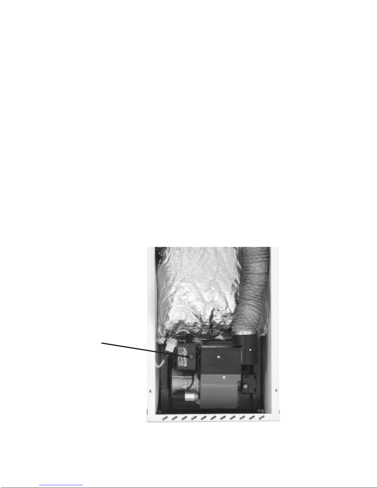
PLEASE NOTE: Also the reset button on the burner will illuminate on the burner control box
at the same time. Reset by pressing the reset button on the burner control box.
4
Reset Button
Burner Control Box

5
SWITCHING THE BOILER OFF
The boiler can be switched off at anytime using one of the following;
- Turn the boiler control thermostat to the OFF position
- Switch the mains (electrical supply) to OFF.
- Set the control system to OFF (e.g. Time clock).
PLEASE NOTE: For longer periods of shutdown e.g. While away on holiday, switch OFF the
mains (electrical supply) and turn OFF the OIL supply.
If shutdown occurs during cold weather ensure boiler is protected against frost damage.
BURNER LOCKOUT
The burner has an independent control system (Burner Control Box); this includes a flame
detector (Photocell) which senses the presence of a flame. In the event of flame failure,
the Burner Control Box activates a second re-ignition sequence. Should the Photocell not
detect a flame presence within 15 seconds the burner goes to LOCKOUT and shuts down.
Continued LOCKOUTS are a result of a fault in the operation of the boiler and can be
attributed to following examples:
- An interruption of the fuel supply .
- Electrical Supply fault e.g. Extreme low voltage.
- Failure of a Burner component.
- A fault within the heating system .
- Burner combustion not being correct.
The Burner Reset button on the Control Box and the red Lockout Indicator on the boiler
control panel illuminates to indicate that a lockout has occurred.
In the event of the Burner locking out, do not attempt to restart the Burner by pressing the
Rest Button on the Burner Control Box for at least 2 minutes. A Bi-metallic timer within the
Control Box has a minimum cooling time of 45 seconds thus the 2 minute interval will
ensure that this Bi-metallic timer has cooled and is therefore in a position where it may be
reset
RESTARTING AFTER LOCKOUT
When lockout has occurred, inspect for any obvious causes e.g. oil leaks.
Also check the fuel line from the tank to the boiler and that any oil shut off valve has not
been inadvertently closed.
6
RESTART
- Check there is adequate oil in the storage tank.
- Check oil supply valves are open.
- Switch on heating system (e.g. Time clock).
- Depress the red Burner Reset Button on the Burner Control Box, which will be illuminated.
Both Burner Reset Button (illuminated) and the lockout Indicator on the Control Panel will go
out and the burner will commence the ignition start sequence. After 15 seconds the Burner
should fire normally.
PLEASE NOTE: Should the Burner not start, both lockout indicator, on the Control Panel and
Burner Reset Button will illuminate again.
- Wait at least 3 minutes and depress the Burner Rest Button again.
Failure to start a second time indicates a fault requiring attention.
In the event of a second failure to start:
- Switch off electrical supply.
- Call service engineer.
Burner Reset Button
7
REGULATIONS
The installation of oil fired boilers should comply with the following standards and codes of
practice.
- BS5449 Forced circulation hot water heating systems for domestic use
- BS5410-Part1 Oil installations up to 45kw.
- BS7593 Water treatment of hot water central heating systems.
- BS7671 Electrical Regulations.
- Building Regulations Part L1 and J 2002 England and Wales, Part F Scottish Regulations
and Technical Booklet L Northern Ireland.
- OFTEC Codes of Practice Published or Recommended.
After installing, the system it needs to be flushed with a cleanser like Fernox Heavy Duty
Restore, for fast-acting removal of lime scale, black sludge (magnetite) and other deposits
from the boiler and the central heating system. Then add a Fernox protector to give long
term protection of the central heating system against internal corrosion and lime scale
formation.
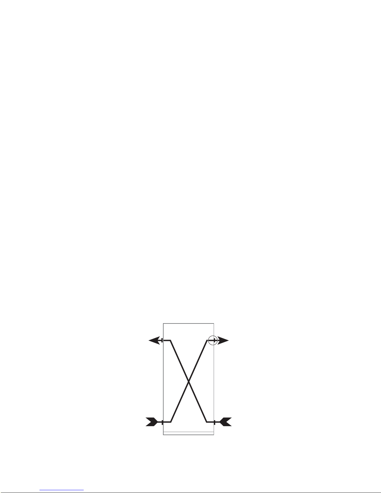
WATER CONNECTIONS
The boiler is supplied with two flow and two return connections. Connections may be
diagonal as shown on diagram below. This arrangement gives more efficient flow through
the boiler, however this is not essential as parallel connection gives satisfactory operation.

8
BOILER LOCATION
Sound levels should be discussed with the householder, as some people may be sensitive
to low noise levels in a small room, as it may appear more annoying than in larger rooms.
Please Note installation should take into account of flue position (see diagram).
RECOMMENDED FLUE POSITION
RefMin. Position mm
ADirectly below an opening, air brick, opening window etc. 600
BHorizontally to an opening , air brick, opening window etc. 600
CBelow a gutter, eaves or balcony with protection. 75
DBelow a gutter or a balcony without protection. 600
EFrom vertical sanitary pipework. 600
FFrom an internal or external corner. 600
GAbove ground or balcony level. 600
HFrom a surface or a boundary facing the terminal. 600
JFrom a terminal facing the terminal. 1200
KVertically from a terminal on the same wall. 1500
LHorizontally from a terminal on the same wall. 750
MAbove the highest point of an intersection with the roof. 600
NFrom a vertical structure on the side of the terminal. 750
OAbove a vertical structure less than 750mm. 600
PFrom a ridge terminal to a vertical structure on the roof. 1500
Please Note where the terminal is within 1 metre of any plastic material, such material
should be protected from the effects of the combustion products of the fuel.
IMPORTANT 35 SECOND CLASS D GAS OIL MUST NOT BE USED FOR BALANCED FLUES.

9
CONVENTIONAL FLUE INSTALLATION
The boiler is supplied as standard for use with conventional flue.
The chimney must comply with building regulations and BS 5410. Factory made insulated
chimneys are covered by BS 4543 Parts 2 & 3.
Notes on Conventional Flue
1. Liner A stainless steel flue liner of diameter to suit the boiler is recommended.
2. Flue pipe can be of vitreous enamel or stainless steel.
3. Bends Bends in the flue pipe should not be greater than 135 degrees.
4. Insulation Insulation between the flue pipe and brick chimney, is recommended to
minimize the occurrence of condensation.
5. Cowls Cowls and pots that may restrict the flue should not be used.
6. Draught Stabiliser Chimneys over 6 metres high may produce excessive draught (over
4mm w.g.). In this case a draught stabilizer may be required.
7. Length Before bends are applied, length of flue must be at least 600mm.
COMBUSTION AIR SUPPLY -CONVENTIONAL FLUE
INFORMATION SUPPLIED BY OFTEC Conventional Flue - Typical Arrangement
550mm2/kw
1100mm2/kw
1650mm2/kw
550mm2/kw
1100mm2/kw
OPEN FLUE BOILER IN ROOM
OPEN FLUE BOILER COMPARTMENT
VENTILATED FROM OUTSIDE
OPEN FLUE BOILER COMPARTMENT
VENTILATED FROM ROOM
550mm2/kw
Terracotta Pot
Liner
Soot
Door
Soot
Door
Flue Pipe
Insulation
Bends135˚
180 TO 450
B
C
SIDE OUTLET LEFT
180 TO 450
B
REAR OUTLET
10
BALANCED FLUE INSTALLATION
VENTILATION AIR SUPPLY
Air ventilation for balanced flue boilers is only required if the boiler is installed in a confined
space e.g. a cupboard. This is to prevent over heating of components.
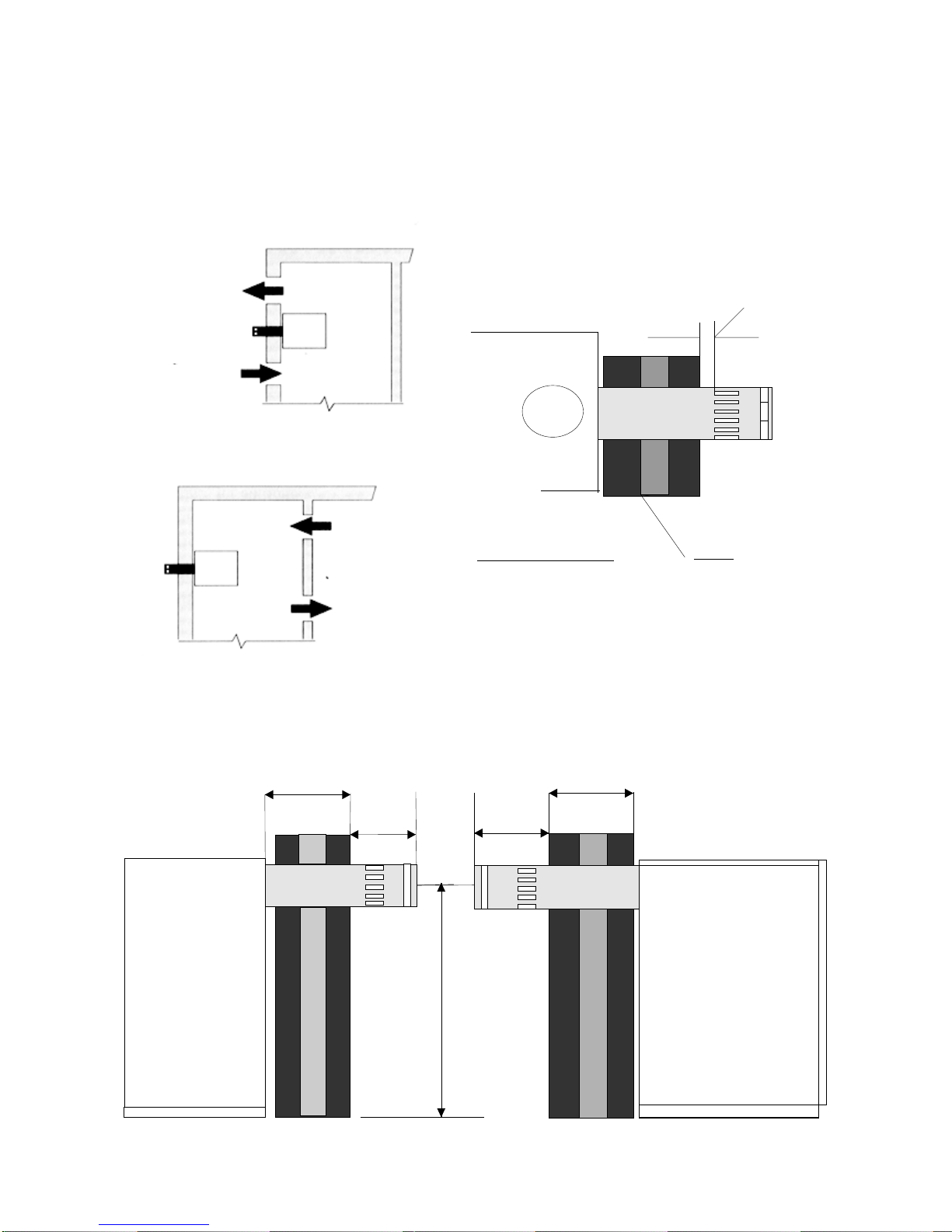
COMBUSTION AIR SUPPLY
25MM M IN
WALL
TERMINAL LENGTH
COMBUSTION AIR SUPPLY
BALANCED FLUE BOILERS
550mm /kW
2
550mm /kW
2
BOILER IN COMPARTMENT
VENTED FROM OUTSIDE
1100mm /kW
2
1100mm /kW
2
Top view on next page
LOW LEVEL BALANCED FLUE
BALANCED FLUE BOILERS
BOILER IN COMPARTMENT
VENTED FROM ROOM

11
LOW LEVEL BALANCED FLUE
A
D
REMOVE FOIL REMOVE FLUE RING FIT SQUARE GASKET
RETAIN BOLTS FOR
FITTING FLUE FIT SEALS AND
LUBRICATE
LOW LEVEL BALANCED FLUE SIDE AND REAR ASSEMBLY INSTALLATION
1. Cut hole in wall. Remember measure, mark, CHECK then cut.
2. Remove Conventional Flue ring from top of boiler.
3. Fit Red inner seal and Black out Seal to flue connector and
extension if required.
4. Apply lubricant included in kit. To the inner and outer seal taken
care to only lubricant the lip of the seal.
MODEL Flue A B C D
50/70 3” 125 176 765 130
70/90 3” 125 176 765 130
90/115 3” 125 176 803 130
115/140 4” 150 185 917 138
140/170 4” 150 185 917 138
REMOVE CASING LID
TEST POINT
TERMINAL GUARD
A Terminal Guard must be fitted to low
level Flue Terminal below 2 metres and
where persons or animals could come into
contact with the terminal or if it could be
subject to damage.

12
5. With boiler in position pass the flue assembly
through the wall and bolt the bottom section of the
flue to the boiler, insuring that square gasket is in
between the boiler and the flue.
6. Attached the snorkel tube with clips to the flue.
7. Make sure that flue terminal protrudes through the
wall a minimum of 176mm for 80mm flue and
185mm for 100mm flue.
FLUE EXTENSION
The maximum horzontal flue level is 1450mm this
can be achieved using the following extension kits:
3 x kit 3 300mm extension
OR
1 x kit 6 950mm extension
8. Remove CF adaptor from burner and discard.
9. Fit the gasket and B F adaptor and connect snorkel
Tube.
N.B. Kit 8 45 degree bends must not be used on low
level balanced flue kits.
HORIZONTAL FLUE
FIT BOLTS
FIT SNORKEL TUBE
FIT CLIP
INTERNAL VIEW
13
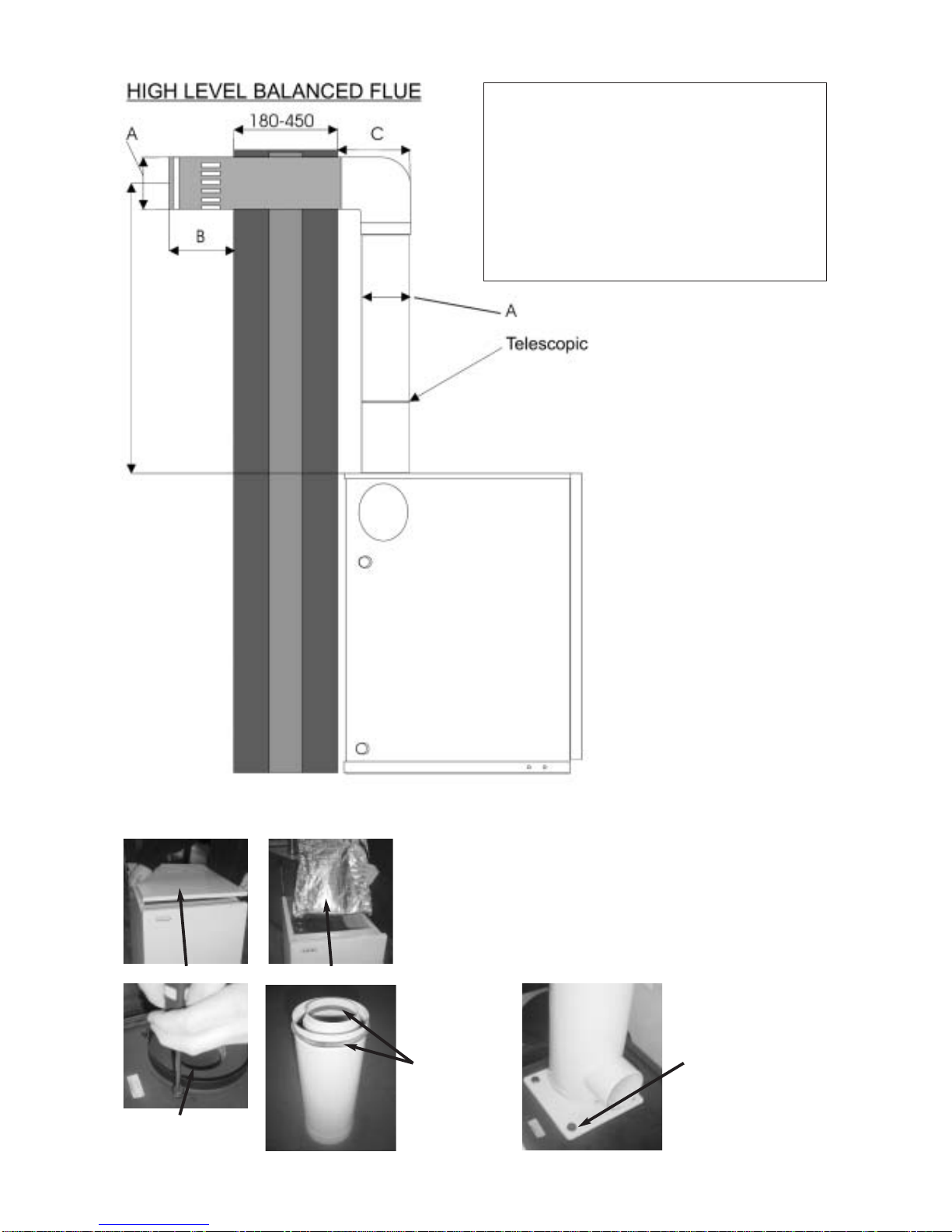
HIGH LEVEL ROOM SEALED BALANCED FLUE DIMENSIONS
INSTALLATION OF HIGH LEVEL BALANCED FLUE
1. Position boiler and Cut Hole in wall. Remember
measure, mark, CHECK then cut.
2. Remove Conventional flue ring from top of boiler.
REMOVE CASING LID REMOVE FOIL
REMOVE FLUE RING
FIT SEALS AND
LUBRICATE BOLT BOTTOM SECTION
TO BOILER
TEST POINT
MODEL Flue A B C
50/70 3” 125 176 200
70/90 3” 125 176 200
90/115 3” 125 176 200
115/140 4” 150 185 230
140/170 4” 150 185 230
50/115
700-
1100 mm
145/170
700-
1100mm
14
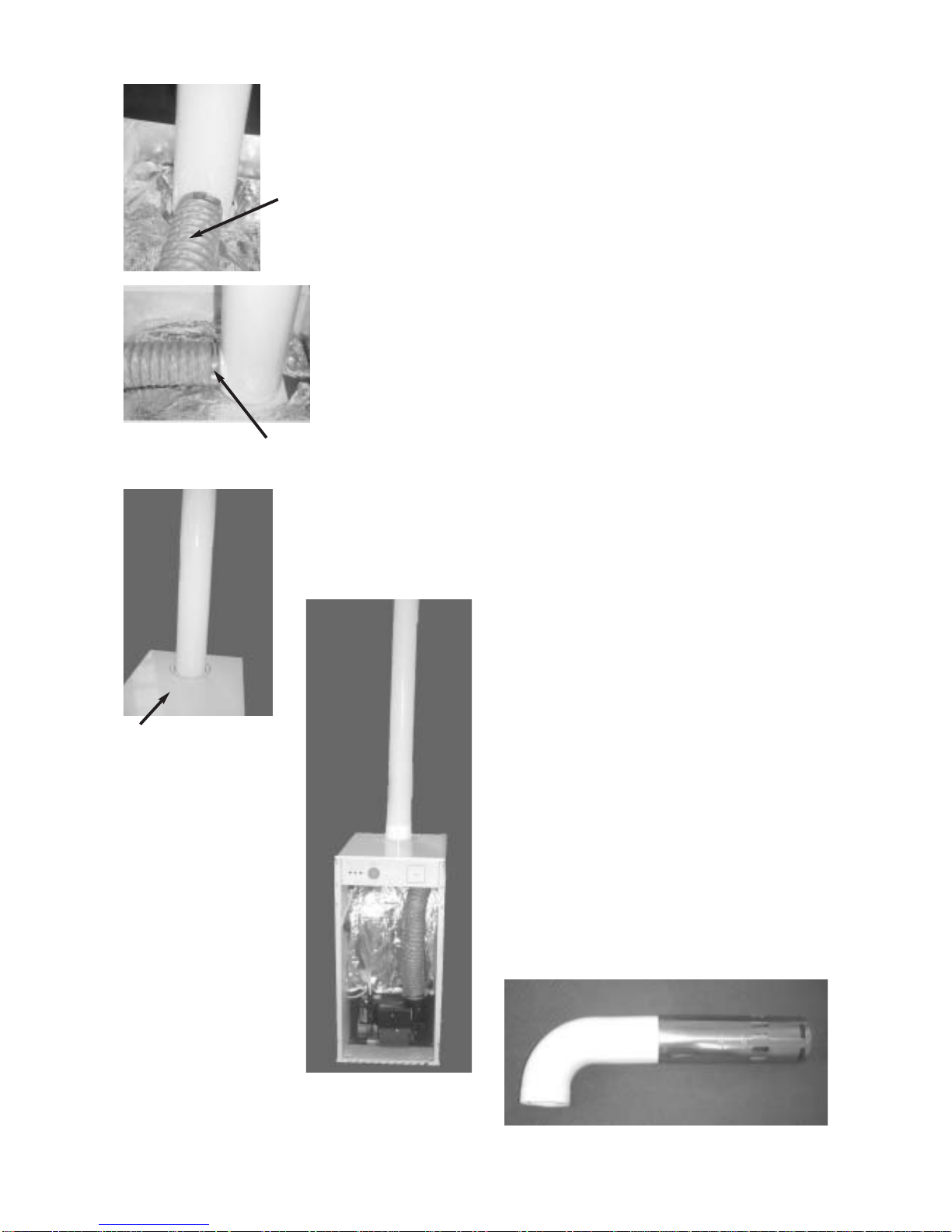
3. Fit Red inner seal and Black outer seal to flue
connectors and extensions if required.
4. Apply lubricant to the inner and outer seals. Taken
care to only lubricant the lip of the seals.
5. Bolt bottom section of the flue to the boiler
insuring the square gasket is fitted in between the
boiler and the flue.
6. Attached snorkel to the flue with the clip.
7. Refit boiler top panel insure the knock out in the
panel has been removed.
8. Assemble second vertical flue section and any
vertical extension.
9. Assemble horizontal section and pass through the
wall. Making sure that the terminal protudes
through the wall a minimum of 176mm for 80mm
flue and 185mm for 100mm flue.
10. Connect vertical and horizontal section together.
11. Secure vertical section with the screws provided.
12. Seal around the flue terminal in wall using mastic.
13. Remove CF adaptor from burner and discard.
14. Fit BF adaptor connect snorkeltube with clip.
NOTE: Expanding foam can be used to fill/insulate
the gap between flue parts and wall.
FLUE EXTENSIONS
Please note a maximum of one kit 6
950mm or 3 x kit 3 300mm extension
can be used on the high level.
Kit 8 45 degree bends must not be used
on high level balanced flue kits.
FIT SNORKEL TUBE
FIT HORIZONTAL SECTION
FIT CLIP
FIT LID
INTERNAL VIEW

15
VERTICAL BALANCED FLUE
2.4
METRE
MINIMUM 600MM
VERTICAL BALANCED FLUE DIMENSIONS
50/70
70/90
90/115
125MM
FLASHING NOT
SUPPLIED
115/140
150MM
140/170
The vertical flue is telescopic as supplied.
The flue has a range of 1020-2400mm
from the top of the boiler to the flashing.
Extension kits of 300 and 950mm
are available.
The maximum vertical length is 4800mm.
Also available are 45 degree bends.
For further information contact our sales office.
N.B. Every 45 degree elbow is equivalent to
500mm of flue.
16
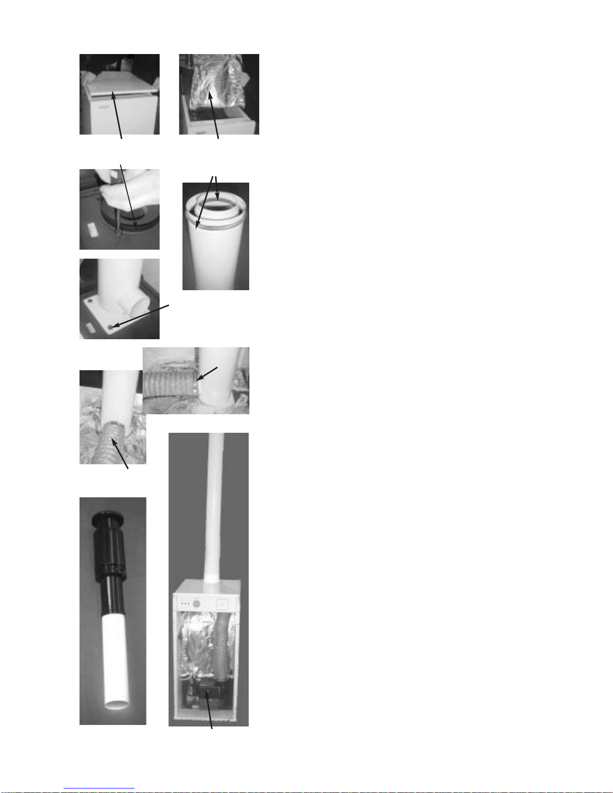
INSTALLATION OF VERTICAL FLUE
1. Position boiler and cut hole/s in ceiling and roof.
Remember measure mark ,CHECK then cut.
2. Remove conventional flue ring from top of boiler.
3. Fit Red inner seal and Black outer seal to flue
connectors and extensions if required.
4. Apply lubricant to the inner and the outer seals.
Taking care to only lubricant the lip of the seals.
5. Bolt bottom section of the flue to the boiler
insuring the square gasket is fitted in between the
boiler and the flue.
6. Attached snorkel to the flue with the clip.
7. Refit boiler top panel insure the knock out in the
panel has been removed.
8. Assemble second vertical flue section and any
vertical extension.
9. Fit the roof flashing and flue terminal.
10. Secure the terminal to a roof joist with clamps
provided.
11. Fit flue elbows if required and secure vertical
section with the screws provided
12. Seal around the flue terminal in wall using mastic
13. Remove CF adaptor from burner and discard
14. Fit BF adaptor connect snorkel tube with clip.
NOTE: Expanding foam can be used to
fill/insulate the gap between flue parts and wall.
Remove lid
Remove flue ring
Bolt bottom section
Fit Clip
Fit Snorkel Tube
Vertical Terminal Internal View
Fit seals and
lubricant
Remove lid

FITTING OF BF ADAPTOR
Disconnect Burner Plug
Fit B F Adaptor
Fit B F Adaptor Gasket
Peel backing sticky
from B F adaptor
Gasket
Remove C F Adaptor
Tighten bolt on burner Fit snorkel tube
Internal view
Loosen Bolt Remove Burner
17

FLUE KIT DESCRIPTION AND PART NUMBERS
DESCRIPTION PART NUMBER
50-115,000BTU 115.000-170,000BTU
1. LOW LEVEL BALANCED FLUE STANDARD KIT1-80mm KIT1-100mm
WALL THICKNESS FROM 150-450mm
2. LOW LEVEL BALANCED FLUE EXTENDED KIT2-80mm KIT2-100mm
WALL THICKNESS FROM 260-600mm
3. 300mm FLUE EXTENSION KIT3-80mm KIT3-100mm
4. HIGH LEVEL HORIZONTAL FLUE KIT4-80mm KIT4-100mm
5. VERTICAL FLUE KIT5-80mm KIT5-100mm
6. 950 MM FLUE EXTENSION KIT6-80mm KIT6-100mm
7. 45 DEGREE BENDS KIT8-80mm KIT8-100mm
N.B. Kit 8 (45 degree bends) must only be used on kit 5 vertical flue kits.
OIL FULL LEVEL
OIL LOWEST LEVEL
VENT FILL
SIGHT
GAUGE
OIL TANK
Plastic tank shown
Steel tank also suitable
FIRE VALVE
ALTERNATIVE
FILTER POSITION
VALVE
PAPER ELEMENT FILTER
BURNER
BOILER
BEST POSITION
FOR FIRE
VALVE SENSOR
REMOTE FIRE
VALVE MUST BE
OUTSIDE THE
BUILDING
TYPICAL SYSTEM SHOWN
Single Pipe Oil System
OIL SUPPLY
18
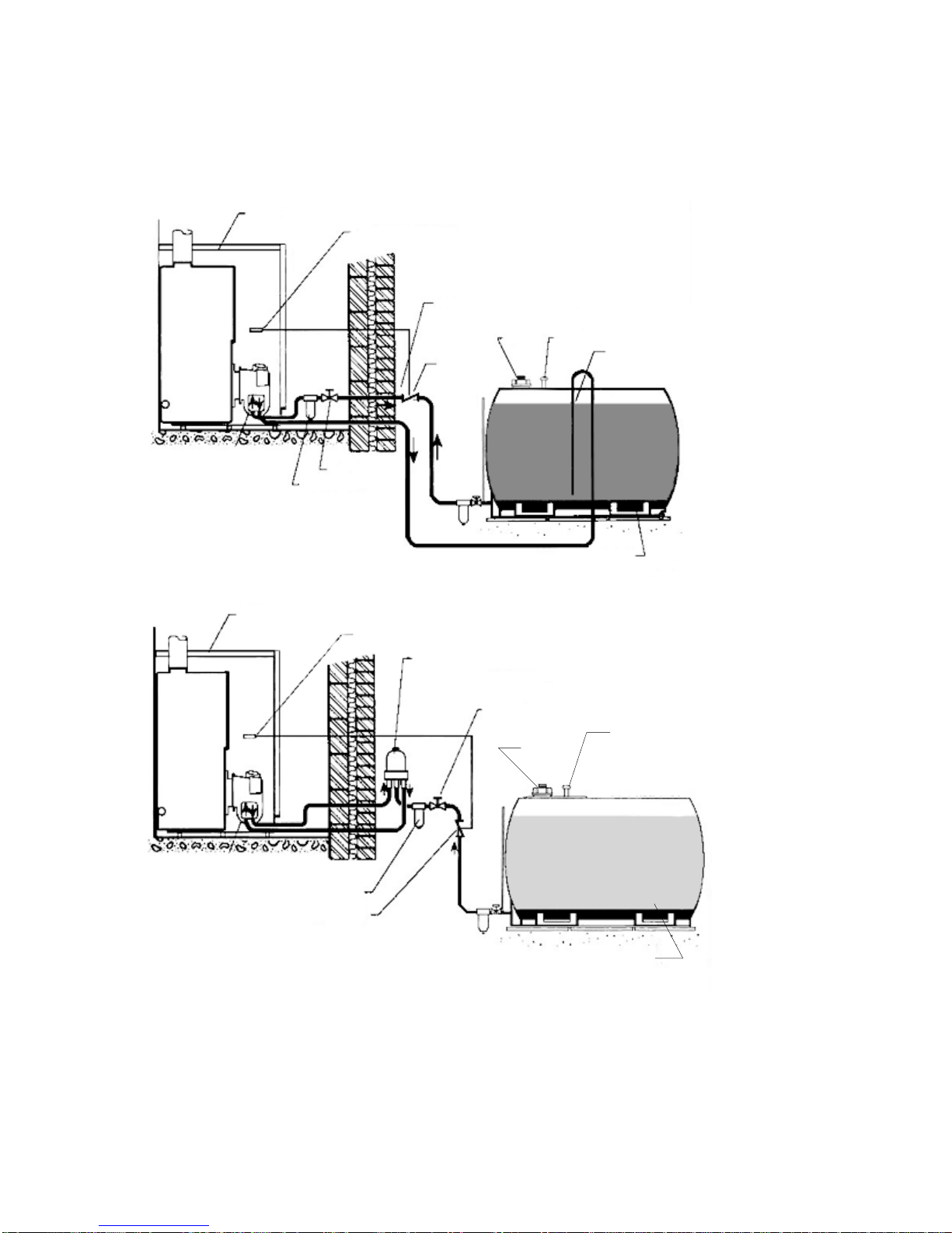
OIL SUPPLY
Diagrams of twin pipe oil supply systems
BOILER
FIRE VALVE SENSOR
ALTERNATIVE FILTER POSITION
FIRE
VALV E
FILL VENT SAW CUT INSIDE
TANK TO PREVENT
SYPHON
OIL TANK
Plastic tank shown steel
tank also suitable
BURNER
PAPER ELEMENT
FILTER
VALV E
PAPER ELEMENT FILTER
BOILER
FIRE VALVE SENSOR
TIGER LOOP MUST BE
1.UPRIGHT
2.OUTSIDE RESIDENCE
Can be above or below burner
VALV E
FILL VENT
OIL FULL LEVEL
OIL LOWEST LEVEL
OIL LEVEL FULL
OIL LOWEST LEVEL
FIRE VALVE
OIL TANK
Plastic tank shown
steel tank also suitable
A flexible oil pipe is supplied to connect the burner to the incoming oil supply pipe.
IMPORTANT NOTES
- If siting oil tank above burner height, use single supply pipe only.
- If siting oil tank below burner height, use twin pipe supply or Tiger loop.
19
Table of contents
Popular Boiler manuals by other brands

broag
broag SEAGOLD 1A HR manual

Viessmann
Viessmann Vitodens 222-F Installation and service instructions

Glowworm
Glowworm 12hx Installation and servicing

Slant/Fin
Slant/Fin VGH-80-CH User's information manual

STOKVIS ENERGY SYSTEMS
STOKVIS ENERGY SYSTEMS ECONOPLATE H1 Installation, commissioning and servicing instructions

Immergas
Immergas EOLO STAR 24 3 E Instruction booklet and warning

eta
eta PelletsCompact 20-32 kW Operation

Weil-McLain
Weil-McLain Aqua Balance WMB-155 manual

Grant
Grant External Vecta Installation and servicing instructions

Ideal Boilers
Ideal Boilers VOGUE COMBI GEN2 C26 installation & servicing

Alpha
Alpha Alpha HE25 Installation and servicing instructions

IDEAL
IDEAL m30100 Installation and servicing guide


