Theta Digital Casablanca III User manual

THETA DIGITAL
CORPORATION
Casablanca III
Owner’s Manual
V 3.00 Rev A a
Digital Done Right
™

PREFACE CONGRATULATIONS
You have just acquired the most advanced component for the control and processing of audio and video ever to
have been developed.
IMPORTANT
Save all packaging in a dry place away from fire hazards. Your Casablanca III is a precision electronic
instrument and should be properly packaged any time shipment is made. In the unlikely event that you have to
return your Casablanca III to the factory for service, or if you send it to us for updating, the original packaging
will best protect the unit from shipping damage.
In order to achieve the fullest flexibility and enjoyment from your Casablanca III, we at Theta recommend that
you read this manual in full before connecting the unit to your audio/video system.
WARNING
United Stated law prohibits disposition of these commodities to Libya, Laos, North Korea, Cambodia or Cuba
unless otherwise authorized by the United States.
NOTE:
This equipment has been tested and found to comply with the limits for a Class B digital device, pursuant to Part
15 of the FCC rules. These limits are designed to provide reasonable protection against harmful interference in
a residential installation. This equipment generates, uses and can radiate radio frequency energy and, if not
installed and used in accordance with the instructions, may cause harmful interference to radio
communications. However, there is no guarantee that interference will not occur in a particular installation. If
this equipment does cause harmful interference to radio and television reception, which can be determined by
turning the equipment off and on, the user is encouraged to try to correct the interference by one or more of the
following measures:
* Reorient or relocate the receiving antenna.
* Increase the separation between equipment and receiver.
* Connect the receiver into an outlet on a circuit different from that which the Casablanca III is connected to.
Acknowledgments
Casablanca III is manufactured under license from Dolby Laboratories. “Dolby”, “Pro Logic”, “Surround EX”,
and the double-D symbol are trademarks of Dolby Laboratories. Copyright 2003 Dolby Laboratories, Inc. All
rights reserved. S03/14905.
Casablanca III is manufactured under license from Digital Theater Systems, Inc. U.S. Pat. No's. 5,451,942;
5,956,674; 5,974,380; 5,978,762; 6,487,535 and other U.S. and world-wide patents issued and pending. "DTS",
"DTS Digital Surround", "DTS-ES", "Neo:6" and "DTS 96/24" are trademarks of Digital Theater Systems, Inc.
Copyright 1996, 2003 Digital Theater Systems, Inc. All Rights Reserved.
Casablanca III is manufactured under license from SRS Labs, Inc. Circle Surround, SRS and symbol are
trademarks of SRS Labs, Inc
©2000-03 Theta Digital Corporation. All rights reserved.
Written and illustrated by Glenn Buckley.
This manual is also available for download as a PDF file at Theta Digital’s website. http://www.thetadigital.com
No part of this publication may be reproduced or transmitted in any form or by any means, electronic or
mechanical, for any purpose, without the express written permission of Theta Digital Corporation.
ii

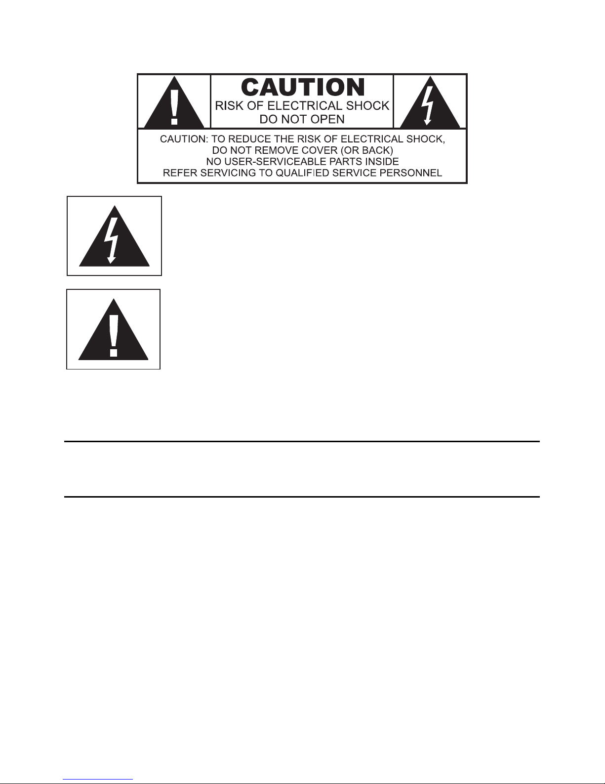
The lightning flash with arrowhead symbol, within an equilateral
triangle, is intended to alert the user to the presence of uninsulated
“dangerous voltage” within the product’s enclosure that may be of
significant magnitude to constitute a risk of electric shock to persons.
The exclamation point within an equilateral triangle is intended to alert
the user to the presence of important operating and maintenance
(servicing) instructions in the literature accompanying the product.
WARNING TO REDUCE THE RISK OF FIRE OR ELECTRIC SHOCK,
DO NOT EXPOSE THIS PRODUCT TO RAIN OR MOISTURE
CAUTION: TO PREVENT ELECTRIC SHOCK, DO NOT USE THE (POLARIZED) PLUG WITH AN
EXTENSION CORD, RECEPTACLE OR OTHER OUTLET UNLESS THE BLADES CAN BE FULLY
INSERTED TO PREVENT BLADE EXPOSURE.
iii

Casablanca III Identification Record
This information is for your records and for future identification of the Casablanca III. Please take a moment
to fill out all pertinent data now, and as upgrades and/or options are installed. Whenever upgrades,
inquiries and/or changes are requested, the serial number will be required.
SERIALNUMBER
DATE PURCHASED
DEALER’SNAME
DEALER’S ADDRESS/PHONE
INSTALLED CARDS/OPTIONS
(Dateofinstallation)
iv

SAFETY PRECAUTIONS
Please carefully read each item of the operating instructions and safety precautions before using this
product. Use extra care to follow the warnings written on the product itself and/or in the operating
instructions. Keep the operating instructions and safety precautions for future reference.
CAUTION: TO REDUCE THE RISK OF ELECTRICAL SHOCK, DO NOT REMOVE ANY OF THE COVER
PANELS.
NO USER-SERVICEABLE PARTS INSIDE. REFER ALL SERVICING TO QUALIFIED SERVICE
PERSONNEL ONLY.
TO PREVENT FIRE OR SHOCK HAZARD, DO NOT ALLOW LIQUIDS TO SPILL OR OBJECTS TO FALL
INTO ANY OPENINGS OF THE PRODUCT.
THIS UNIT IS SUPPLIED WITH A 3 PIN GROUNDED AC PLUG. ALWAYS INSERT THE AC PLUG INTO
A GROUNDED OUTLET. DO NOT REMOVE THE GROUND PIN OR DISABLE THE GROUND FOR ANY
PURPOSE.
BEFORE MAKING ANY CONNECTIONS TO THE CASABLANCA III, FIRST TURN OFF THE POWER
AND THEN DISCONNECT THE AC POWER CORD.
WHEN INSTALLING THE CASABLANCA III IN YOUR SYSTEM, MAKE CERTAIN TO ALLOW A
MINIMUM OF 3 INCHS OF VENTILATION ON EACH SIDE OF THE UNIT. ALSO ALLOW AT LEAST 3½
INCHS OF VENTILATION SPACE ABOVE THE UNIT. IMPROPER VENTILATION OF THE UNIT MAY
CAUSE OVERHEATING, WHICH MAY DAMAGE THE UNIT AND CAUSE A FIRE. PLACE THE UNIT ON
A SOLID SURFACE ONLY. I.E. NOT ON CARPET, ETC.
DO NOT PLACE THE CASABLANCA III NEAR HEAT SOURCES SUCH AS DIRECT SUNLIGHT,
STOVES, HEAT REGISTERS, RADIATORS OR OTHER HEAT PRODUCING EQUIPMENT.
TO PREVENT DAMAGE TO THE ANALOG OUTPUT CIRCUITRY, BE CERTAIN NOT TO SHORT THE
OUTPUT SIGNAL PIN(S) TO GROUND. ENSURE THAT YOUR AUDIO OUTPUT CABLES DO NOT
HAVE ANY INTERNAL SHORTS BEFORE CONNECTING THEM TO THE CASABLANCA III.
IF REPLACEMENT OF THE AC LINE FUSE BECOMES NECESSARY, REPLACE ONLY WITH SAME
VALUE AND TYPE OF FUSE. NEVER BYPASS THE FUSE.
IF THE AC CORD BECOMES DAMAGED, DO NOT USE IT. IMMEDIATELY REPLACE IT WITH A NEW
ONE OF THE SAME OR BETTER RATING.
AFTER MARKET and THIRD PARTY MODIFICATIONS
Please note that any after market and/or third party modifications will void the warranty. In the case of
changing the feet on a unit, in order to prevent any damage (which will also not be covered under warranty),
please verify that the screws being used to secure non Casablanca III feet do not screw any deeper into the
chassis than the original ones. The original screw is 10-32 by 3/8 and goes into the chassis 1/5 inch.
v

Table of Contents
PREFACE............................................................................................................................................................................ii
WARNING ......................................................................................................................................................................iii
Casablanca III Identification Record................................................................................................................................iv
SAFETY PRECAUTIONS................................................................................................................................................v
AFTER MARKET and THIRD PARTY MODIFICATIONS............................................................................................v
List of Figures .................................................................................................................................................................ix
List of Tables....................................................................................................................................................................x
INTRODUCTION .................................................................................................................................................................1
Getting to know your Casablanca III ................................................................................................................................1
Burn In Time ................................................................................................................................................................1
IMPORTANT NOTICE.....................................................................................................................................................2
Reference Manual Conventions.......................................................................................................................................2
Glossary of Terms and Abbreviations..............................................................................................................................3
Casablanca III Block Diagram - Input Processing Sections .............................................................................................4
Casablanca III Block Diagram - DAC and Analog Out Sections.......................................................................................6
Front Panel Layout...........................................................................................................................................................8
Rear Panel Layout ...........................................................................................................................................................9
Menu Maps....................................................................................................................................................................12
Function Menus and Pages .......................................................................................................................................12
Input Select Pages.....................................................................................................................................................12
Setup Menus and Pages............................................................................................................................................13
Introduction to the User interface...................................................................................................................................14
WARNING !! : PLEASE READ FIRST! ....................................................................................................................14
Before you begin........................................................................................................................................................14
STEP-BY-STEP SETUP GUIDE........................................................................................................................................15
Casablanca III Overall Setup Procedure Flowchart........................................................................................................16
Step by Step Speaker Configuration..........................................................................................................................17
Speaker Configuration & Crossovers.....................................................................................................................17
Phase Perfect.....................................................................................................................................................17
Butterworth.........................................................................................................................................................18
Linkwitz-Riley.....................................................................................................................................................18
A note on crossovers .....................................................................................................................................18
A note on home theater..................................................................................................................................18
Speaker Configuration & Crossovers – Con’t.........................................................................................................19
Speaker Levels ..........................................................................................................................................................20
Speaker Delays..........................................................................................................................................................21
Dolby Digital, DTS and Circle Surround Setup...........................................................................................................22
Remaining Setup........................................................................................................................................................23
Setup Flowcharts A-P ................................................................................................................................................24
FRONT PANEL OPERATIONS.........................................................................................................................................40
Input Select Menus ........................................................................................................................................................40
Changing Inputs and Input Select Pages...................................................................................................................40
Selecting Mapped Input Jacks for the Currently Selected Input.................................................................................40
Search Order .............................................................................................................................................................41
MODE Function .............................................................................................................................................................42
TAPE OUT Function......................................................................................................................................................45
Standard Tape Out Configuration ..............................................................................................................................46
Optional Upgrade Tape Out Configuration.................................................................................................................46
SETUP Function............................................................................................................................................................47
Setup Button Password..............................................................................................................................................47
DAC Configuration.....................................................................................................................................................47
SETUP INPUT (Setting up each of the 12 Input Select Buttons) ...............................................................................48
Setup Input Page 1 ................................................................................................................................................48
Setup Speaker Configuration.............................................................................................................................48
SUB Configuration .........................................................................................................................................49
Left/Right Speaker Configuration ...................................................................................................................50
Crossovers.....................................................................................................................................................51
Center Speaker Configuration........................................................................................................................53
Left/Right Surround Speaker Configuration....................................................................................................54
Center Surround Speaker Configuration........................................................................................................54
Side Speaker Configuration ...........................................................................................................................54
Speaker Levels ..................................................................................................................................................55
Internal Noise Generator................................................................................................................................55
Speaker Delays..................................................................................................................................................57
Default Mode......................................................................................................................................................58
Onscreen Display (OSD) Setup .........................................................................................................................59
Status Setup...................................................................................................................................................59
VFD Brightness..............................................................................................................................................59
Setup Input Page 2 ................................................................................................................................................60
vi

vii
LFE Phase.........................................................................................................................................................60
Mapping an Audio and Video Source (Input Jack to INPUT SELECT button)....................................................60
Setup Dolby Digital.............................................................................................................................................62
2 Channel Mode.............................................................................................................................................62
Compression..................................................................................................................................................62
Dialog Normalization......................................................................................................................................62
Setup DTS .........................................................................................................................................................64
Setup Circle Surround........................................................................................................................................64
Post Process......................................................................................................................................................65
Setup Input Page 3 ................................................................................................................................................65
Setup Miscellaneous..........................................................................................................................................66
Naming the Current Input Select button.........................................................................................................66
Master Delay......................................................................................................................................................66
Password for Each INPUT SELECT Button.......................................................................................................66
Center Spread....................................................................................................................................................66
Setup Global ..............................................................................................................................................................67
Analog Input Levels................................................................................................................................................67
Jack Names...........................................................................................................................................................68
Remote Power Jacks .............................................................................................................................................68
Clear Balance (Temporary Settings Control).........................................................................................................69
RS232....................................................................................................................................................................69
Mute/Volume..........................................................................................................................................................70
Initial Power-On Master Volume.........................................................................................................................70
FVOL and SVOL................................................................................................................................................70
Maximum Overall Level......................................................................................................................................70
Changing the Default MUTE Level.....................................................................................................................70
MUTE Off Trigger...............................................................................................................................................70
Cursor Type ...........................................................................................................................................................71
Displaying Mode Change Messages......................................................................................................................71
Display Time ..........................................................................................................................................................71
Serial Number........................................................................................................................................................71
Macros.......................................................................................................................................................................72
Copy Macros..........................................................................................................................................................72
Restore Macros......................................................................................................................................................72
BALANCE Function........................................................................................................................................................74
Front/Rear and Left/Right Balance.............................................................................................................................74
Center and Sub Balance............................................................................................................................................74
Shelf EQ.....................................................................................................................................................................74
Analog Input Level Override.......................................................................................................................................75
STATUS Function..........................................................................................................................................................76
Remote Control Layout..................................................................................................................................................79
REMOTE CONTROL OPERATIONS.................................................................................................................................80
Input Select Menus ........................................................................................................................................................80
Changing Inputs and Input Select Pages...................................................................................................................80
Selecting Mapped Input Jacks for the Currently Selected Input.................................................................................80
Mute...........................................................................................................................................................................80
Display.......................................................................................................................................................................80
Global Phase .............................................................................................................................................................80
STATUS Display............................................................................................................................................................81
MODE Function .............................................................................................................................................................82
TAPE OUT Function......................................................................................................................................................83
SETUP Function............................................................................................................................................................84
Setup Button Password..........................................................................................................................................84
DAC Configuration.....................................................................................................................................................84
SETUP INPUT (Setting up each of the 12 Input Select Buttons) ...............................................................................85
Setup Input Page 1 ................................................................................................................................................85
Speaker Configuration .......................................................................................................................................85
Left/Right Speaker Configuration ...................................................................................................................85
Center Speaker Configuration........................................................................................................................86
Surround Speaker Configuration....................................................................................................................87
Sub Woofer Configuration..............................................................................................................................87
Surround Center Configuration ......................................................................................................................88
Side Speaker Configuration ...........................................................................................................................88
Speaker Levels ..................................................................................................................................................88
Speaker Delays..................................................................................................................................................89
Default Mode......................................................................................................................................................90
Onscreen Display (OSD) Setup .........................................................................................................................90
Status Setup...................................................................................................................................................90
VFD Brightness..............................................................................................................................................91
Setup Input Page 2 ................................................................................................................................................91
LFE Phase.........................................................................................................................................................91

viii
Mapping a Source (Input Jack to INPUT SELECT button).................................................................................91
Setup Dolby Digital.............................................................................................................................................92
2 Channel Mode.............................................................................................................................................92
Compression..................................................................................................................................................92
Dialog Normalization......................................................................................................................................93
Setup DTS .........................................................................................................................................................94
Setup Circle Surround........................................................................................................................................94
Post Process......................................................................................................................................................95
Setup Input Page 3 ................................................................................................................................................95
Setup Miscellaneous..........................................................................................................................................95
Naming the Current Input Select button.........................................................................................................95
Master Delay......................................................................................................................................................96
Password for Each INPUT SELECT Button.......................................................................................................96
Center Spread....................................................................................................................................................96
Setup Global ..............................................................................................................................................................97
Analog Input Levels................................................................................................................................................97
Jack Names...............................................................................................................................................................97
Remote Power Jacks.................................................................................................................................................98
Clear Balance (Temporary Settings Control).........................................................................................................98
RS232....................................................................................................................................................................99
Mute/Volume..........................................................................................................................................................99
Initial Power-On Master Volume.........................................................................................................................99
FVOL and SVOL................................................................................................................................................99
Maximum Overall Level....................................................................................................................................100
Changing the Default MUTE Level...................................................................................................................100
MUTE Off Trigger.............................................................................................................................................100
Cursor Type .........................................................................................................................................................100
Displaying Mode Change Messages....................................................................................................................101
Display Time ........................................................................................................................................................101
Serial Number......................................................................................................................................................101
Macros.....................................................................................................................................................................101
Copy Macros........................................................................................................................................................101
Restore Macros....................................................................................................................................................102
BALANCE Function......................................................................................................................................................103
Front/Rear and Left/Right Balance...........................................................................................................................103
Center and Sub Balance..........................................................................................................................................103
Shelf EQ...................................................................................................................................................................103
Analog Input Level Override.....................................................................................................................................103
APPENDIXES..................................................................................................................................................................104
Appendix A Troubleshooting Guide.....................................................................................................................105
Appendix B Wiring Diagrams and Speaker Placement Guides ...........................................................................106
Digital Out/External Volume Control Wiring Diagrams.....................................................................109
Appendix C Remote Extender Jack Technical Description and Protocol.............................................................111
Appendix D Upgrading/Re-installing Casablanca III Software .............................................................................112
Appendix E Specifications...................................................................................................................................113
WARRANTY INFORMATION..........................................................................................................................................120

ix
List of Figures
Figure 1 - Block Diagram of Input Processing Sections.......................................................................................................4
Figure 2 - Block Diagram of 8 S-Video Switching Card........................................................................................................5
Figure 3 - Block Diagram of Multi Format/6 S-Video Switching Card...................................................................................5
Figure 4 - Block Diagram of DAC and Analog Outputs ........................................................................................................6
Figure 5 - Block Diagram of Xtreme 4 Channel DAC board.................................................................................................7
Figure 6 - Block Diagram of Digital Output board, showing all options.................................................................................7
Figure 7 - Front Panel Layout ..............................................................................................................................................8
Figure 8 - Rear Panel Layout...............................................................................................................................................9
Figure 9 - All optional Single-Ended D/A Cards .................................................................................................................10
Figure 10 - All optional Standard Balanced D/A Cards ......................................................................................................10
Figure 11 - All optional Superior D/A Cards and the Digital Output card with Center Channel...........................................11
Figure 12 - Xtreme DAC.....................................................................................................................................................11
Figure 13 - Mode, Status, Balance, Tape Out Menus and Input Select Pages..................................................................12
Figure 14 - Setup Menus and Pages..................................................................................................................................13
Figure 15 - Front Panel Display of the current INPUT SELECT page................................................................................40
Figure 16 - Front Panel Display of the SETUP/INP page 2/SOURCE/AUD page..............................................................41
Figure 17 - Front Panel Display of the MODE Page 1 Menu..............................................................................................42
Figure 18 - Front Panel Display of the MODE Page 2 Menu..............................................................................................43
Figure 19 - Front Panel Display of the TAPE OUT Menu...................................................................................................45
Figure 20 - Front Panel Display of the SETUP Menu.........................................................................................................47
Figure 21 - Front Panel Display of the SETUP/Assign Password Display..........................................................................47
Figure 22 - Front Panel Display of the SETUP/INPUT page 1 Submenu...........................................................................48
Figure 23 - Menu Map of SETUP/INP Page 1/CONFIG.....................................................................................................48
Figure 24 - Front Panel Display of the Speaker Configuration Submenu...........................................................................49
Figure 25 - Front Panel Display of the Subs Configuration Submenu................................................................................49
Figure 26 - Menu Map of SETUP/INP Page 1/CONFIG/LT/RT..........................................................................................50
Figure 27 - Front Panel Display of the Front Left/Right Speaker Configuration Submenu .................................................51
Figure 28 - Front Panel Display of the SETUP/INP/CONFIG/LT/RT/φPERF Sub Menu ....................................................51
Figure 29 - Front Panel Display of the SETUP/INP/CONFIG/LT/RT/Link-R Sub Menu .....................................................52
Figure 30 - Front Panel Display of the SETUP/INP/CONFIG/LT/RT/BWORTH Sub Menu................................................52
Figure 31 - Front Panel Display of the SETUP/INP/CONFIG/CENTER Sub Menu............................................................53
Figure 32 - Front Panel Display of the SETUP/INP/CONFIG/L-R SURRND Sub Menu.....................................................54
Figure 33 - Front Panel Display of the SETUP/INP/LVLS/Channel Choice Sub Menu ......................................................55
Figure 34 - Front Panel Display of the SETUP/INP/LVLS 1-6 Sub Menu...........................................................................55
Figure 35 - Front Panel Display of the SETUP/INP/LVLS 7-12 Sub Menu.........................................................................55
Figure 36 - Front Panel Display of the SETUP/INP/DELAYS 1 Sub Menu ........................................................................57
Figure 37 - Front Panel Display of the SETUP/INP/DELAYS 2 Sub Menu ........................................................................57
Figure 38 - Rear Delay Settings.........................................................................................................................................58
Figure 39 - Front Panel Display of the SETUP/INP/OSD Sub Menu..................................................................................59
Figure 40 - Front Panel Display of the SETUP/INP/OSD/STATUS 1 Sub Menu................................................................59
Figure 41 - Menu Map of SETUP/INP Page 2....................................................................................................................60
Figure 42 - Front Panel Display of the SETUP/INP Page 2 Sub Menu..............................................................................60
Figure 43 - Front Panel Display of the SETUP/INP Page 2/SOURCE/AUD Sub Menu .....................................................61
Figure 44 - Front Panel Display of the SETUP/INP Page 2/DOLBY DIGITAL Page 1 Sub Menu......................................62
Figure 45 - Front Panel Display of the SETUP/INP Page 2/DOLBY DIGITAL Page 2 Sub Menu......................................63
Figure 46 - Front Panel Display of the SETUP/INP Page 2/DTS Sub Menu......................................................................64
Figure 47 - Front Panel Display of the SETUP/INP Page 2/CIRCLE SURRND Sub Menu................................................64
Figure 48 - Front Panel Display of the SETUP/INP Page 2/POST PROCESS Sub Menu.................................................65
Figure 49 - Menu Map of SETUP/INP Page 3....................................................................................................................65
Figure 50 - Front Panel Display of the SETUP/INP Page 3 Sub Menu..............................................................................65
Figure 51 - Front Panel Display of the SETUP/INP page 3/MISC Sub Menu.....................................................................66
Figure 52 - Front Panel Display of the SETUP/GLOBAL page 1/ Sub Menu.....................................................................67
Figure 53 - Front Panel Display of the SETUP/GLOBAL/ANLG LVLS Sub Menu..............................................................67
Figure 54 - Front Panel Display of the SETUP/GLOBAL/JACK NAMES Sub Menu ..........................................................68
Figure 55 - Front Panel Display of the SETUP/GLOBAL/REMPWR Sub Menu.................................................................68
Figure 56 - Front Panel Display of the SETUP/GLOBAL/RS232 Sub Menu ......................................................................69
Figure 57 - Front Panel Display of the SETUP/GLOBAL/MUTE-VOLUME Sub Menu.......................................................70
Figure 58 - Front Panel Display of the SETUP/GLOBAL page 2 Sub Menu......................................................................71
Figure 59 - Front Panel Display of the SETUP/MACROS Sub Menu.................................................................................72
Figure 60 - Front Panel Display of the SETUP/MACROS/RESTORE FACTORY Sub Menu ............................................72
Figure 61 - Front Panel Display of the BALANCE Page 1 Menu........................................................................................74
Figure 62 - Front Panel Display of the BALANCE Page 2 Menu........................................................................................74
Figure 63 - Front Panel Display of the STATUS Display....................................................................................................76
Figure 64 - Front Panel Display of the STATUS/Dolby Digital Page 1 Display...................................................................76
Figure 65 - Front Panel Display of the STATUS/Dolby Digital Page 2 Display...................................................................77
Figure 66 - Remote Control Layout....................................................................................................................................79
Figure 67 - Video Display of the INPUT SELECT Page 1 Menu........................................................................................80
Figure 68 - Video Display of the STATUS Display.............................................................................................................81

x
Figure 69 - Video Display of the First Dolby Digital Status Page........................................................................................81
Figure 70 - Video Display of the Second Dolby Digital Status Page ..................................................................................81
Figure 71 - Video Display of the MODE Page 1 Menu.......................................................................................................82
Figure 72 - Video Display of the MODE Page 2 Menu.......................................................................................................82
Figure 73 - Video Display of the TAPE OUT Menu with Optional Tape Out DAC installed and set to MAIN .....................83
Figure 74 - Video Display of the TAPE OUT Menu with Optional Tape Out DAC installed and set to TAPE.....................83
Figure 75 - Video Display of the SETUP Menu..................................................................................................................84
Figure 76 - Video Display of the SETUP Password Page..................................................................................................84
Figure 77 - Video Display of the SETUP/INPUT Page 1 Sub Menu...................................................................................85
Figure 78 - Video Display of the SETUP/INPUT Page 1/SPEAKER CONFIGURATION Sub Menu..................................85
Figure 79 - Video Display of the SETUP/ INPUT Page 1/CONFIG/LEFT/RIGHT Configuration Sub Menu.......................85
Figure 80 - Video Display of the SETUP/INPUT page 1/SPEAKER CONFIG/ CENTER Sub Menu..................................86
Figure 81 - Video Display of the SETUP/INPUT page 1/CONFIG/SURROUND CONFIGURATION Sub Menu................87
Figure 82 - Video Display of the SETUP/INPUT Page 1/CONFIG/SUB CONFIGURATION Sub Menu ............................87
Figure 83 - Video Display of the SETUP/INPUT page 1/CONFIG/SURROUND CENTER Sub Menu...............................88
Figure 84 - Video Display of the SETUP/ INPUT/LEVELS 1-6 Sub Menu .........................................................................88
Figure 85 - Video Display of the SETUP/INPUT/LEVELS 7-12 Sub Menu ........................................................................89
Figure 86 - Video Display of the SETUP/INPUT/DELAYS 1 Sub Menu.............................................................................89
Figure 87 - Video Display of the SETUP/INPUT/DELAYS 2 Sub Menu.............................................................................89
Figure 88 - Video Display of the SETUP/INPUT Page 3/ON-SCREEN DISPLAY Sub Menu ............................................90
Figure 89 - Video Display of the SETUP/INPUT/OSD/STATUS page 1 Setup Sub Menu.................................................90
Figure 90 - Video Display of the SETUP/INPUT Page 2 Sub Menu...................................................................................91
Figure 91 - Video Display of the SETUP/INPUT Page 2/DOLBY DIGITAL Page 1 Sub Menu ..........................................92
Figure 92 - Video Display of the SETUP/INPUT Page 2/DOLBY DIGITAL Page 2 Sub Menu ..........................................93
Figure 93 - Video Display of the SETUP/INPUT Page 2/DTS Sub Menu...........................................................................94
Figure 94 - Video Display of the SETUP/INPUT Page 2/CIRCLE SURROUND Sub Menu...............................................94
Figure 95 - Video Display of the SETUP/INPUT Page 2/POST PROCESS Sub Menu......................................................95
Figure 96 - Video Display of the SETUP/INPUT Page 3 Sub Menu...................................................................................95
Figure 97 - Video Display of the SETUP/GLOBAL Page 1 Sub Menu...............................................................................97
Figure 98 - Video Display of the SETUP/ANALOG INPUT LEVELS Sub Menu.................................................................97
Figure 99 - Video Display of the SETUP/ INPUT/JACK NAMES Sub Menu......................................................................97
Figure 100 - Video Display of the SETUP/GLOBAL/REMOTE POWER Sub Menu...........................................................98
Figure 101 - Video Display of the SETUP/GLOBAL/RS232 Sub Menu..............................................................................99
Figure 102 - Video Display of the SETUP/GLOBAL/MUTE-VOLUME Sub Menu..............................................................99
Figure 103 - Video Display of the SETUP/GLOBAL Page 2 Sub Menu...........................................................................100
Figure 104 - Video Display of the SETUP/MACROS Sub Menu......................................................................................101
Figure 105 - Video Display of the SETUP/MACROS/RESTORE FACTORY Sub Menu..................................................102
Figure 106 - Video Display of the BALANCE Page 1 Menu.............................................................................................103
Figure 107 - Video Display of the BALANCE Page 2 Menu.............................................................................................103
Figure 108 - Examples of Typical Input and Tape Out Connections................................................................................106
Figure 109 - Recommended Output Wiring Diagram Using 12 Single-Ended channels...................................................106
Figure 110 - Recommended Speaker Placement for Six Channel Configuration.............................................................107
Figure 111 - Recommended Speaker Placement for Twelve Channel Configuration.......................................................107
Figure 112 - Recommended Output Wiring Diagram Using 12 channels (Six Balanced and Six Single-Ended)..............108
Figure 113 - Recommended Output Wiring Diagram Using 8 balanced Xtreme channels...............................................108
Figure 114 - Wiring diagram for the Casablanca III Digital Output board and a 2 Channel External Volume Control unit. ................... 109
Figure 115 - Wiring diagram for the Casablanca III Digital Output board and a 6 Channel External Volume Control unit..................110
List of Tables
Table 1 - Glossary of Terms and Abbreviations...................................................................................................................3
Table 2 - Available configuration settings for front L/R speaker Phase Perfect crossover.................................................52
Table 3 - Available configuration settings for front L/R speaker Linkwitz-Riley crossover..................................................52
Table 4 - Available configuration settings for front L/R speaker Butterworth crossover. ....................................................53
Table 5 - Source to Output Routing for Speaker Level Configuration. ...............................................................................56

1
INTRODUCTION
Welcome to a new world of possibilities. Casablanca III is by far the most advanced surround sound
processor/home theater controller available today. It offers the advantages of Theta’s legendary mastery in
digital signal processing and sound quality unapproachable by any other equipment.
Getting to know your Casablanca III
Despite Casablanca III’s great technical sophistication, we believe in making it as easy as possible for you to
use. We think you’ll enjoy the intuitive way the Casablanca III works. Rather than offer a frustrating
bewilderment of little used functions in constant view, vying for your attention, Casablanca III is structured
systematically by function.
The “user interface” is based on simple logic. For example, when a function button is pressed, you can
make changes within its menu(s) and press the same function button again to exit that function. (The same
button that got you in gets you back out).
This Casablanca III has been put through a rigorous and unique testing procedure that insures that it will last
for many years with minimal service requirements. This procedure includes the following:
•All assembled circuit boards are given a thorough visual inspection and are then tested in a bench-
reference Casablanca III.
•The tested assembled circuit boards are then installed in a new Casablanca III and the whole unit is
tested for every function and parameter.
•The unit is put on a burn-in torture rack for 100 hours to test for any possible component failures.
•The Casablanca III is tested on an audio analyzer for all pertinent parameters.
•The Casablanca III is put through a final bench test wherein every possible feature, mode and
parameter is checked.
•The unit has all remaining chassis components installed and then undergoes a complete visual
inspection, which assures that all Casablanca III’s meet visual specifications.
•The unit is then put through a critical listening test.
Burn In Time
This unit has a break in period of about 1 week during which continuous improvement in sound quality will be
observed. It is recommended that music be played continuously through the unit during this time to expedite
the break in period.

IMPORTANT NOTICE
I. Due to the computer-based circuitry used in Theta products, it is imperative that the Casablanca III
be connected to a ground via its three wire AC power cord. It is important that the AC power outlet,
which the Casablanca III is plugged into, is actually grounded. Failure to do so will severely
compromise the performance, reliability and safety of use of the Casablanca III.
II. It is also important to prevent contact with static electricity when connecting other components and
cables to the Casablanca III. When connecting cables, simply place one hand on top of the
Casablanca III and then grasp the metal “barrel” of the cable with the other hand and plug (unplug)
the cable into (from) the appropriate jack on the Casablanca III.
III. The Casablanca III, as with all electronic equipment, is susceptible to static discharges. Resetting
the unit may be required if anomalies occur after receiving a static discharge. In this case, put the
unit in standby and turn off the rear panel power switch for 2 minutes, and then turn it on again.
IV. Ventilation is an important issue when placing the Casablanca III in a system. Make certain that the
Casablanca III is placed in a well-ventilated area or rack unit.
V. Please take note that some powerline conditioners defeat the AC power ground on their outlets. If
the intention is to plug the Casablanca III into a line conditioner, check with your dealer to make
certain that the particular conditioner that is intended for use DOES NOT DEFEAT THE AC
GROUND on its AC outlets.
VI. DO NOT remove any cover panels from the Casablanca III, as there are no user serviceable
components inside. Refer servicing and updating to qualified service personnel only.
VII. Should the Casablanca III need to be reset, it must be put in standby first via the front panel power
button. Then the rear panel power switch is to be turned off for at least 2 minutes.
VIII. The Casablanca III can be susceptible to excessive RF. End caps in all unused inputs will improve
the sound quality and may reduce the susceptibility to RF induced anomalies.
Reference Manual Conventions
For clarity purposes, references to buttons, LED’s and display parameters will be shown in bold capital
letters.
All functions to be performed from, and in reference to the front panel of the Casablanca III will be found in
the front section of this manual, whereas all functions to be performed using the hand held remote and/or
viewed on a video monitor will be found in the back, or last part of this manual.
2

Glossary of Terms and Abbreviations
TERM DEFINITION
AES/EBU (Audio Engineering Society) / (European
Broadcasters Union) A three wire balanced digital audio standard. This interface uses a 3-pin
XLR type connector and allows for data communication between digital
audio equipment.
Analog-to-Digital Converter A device that converts analog signals into a digital format. Once
encoded, all audio is stored or processed as a series of numbers rather
than as the audio itself.
Balanced Audio Signals Signals that are carried on three-conductor cables, with two of the
conductors carrying the same signal 180° out of phase and the third as
ground. Balanced connections usually cost more than unbalanced
connections, but are less susceptible to picking up hum and prevent
interference with low-level signals.
Center Spread A proprietary Theta Digital process whereby the front center speaker
signal can be incrementally spread evenly between the front left and right
speakers.
dB Decibel, a relative unit of loudness.
Dolby 3 Stereo The Dolby 3 Stereo mode reproduces sound using only the 3 front
channels, and is intended to be used either before surround speakers are
installed, or for programs that might benefit from deriving a center
channel output, but where the quality of the surround output is
unsatisfactory.
Digital-to-Analog Converter A device that converts digital signals into an analog format.
Hz (Hertz) A unit of frequency.
IR Infrared. A method of wireless transmission of data.
LFE Low Frequency Effect. Commonly a discrete audio track designated for a
sub woofer.
mS Millisecond, or 1\1000 of a second.
Oversampling The process of taking more samples than is required in order to more
accurately reconstruct a digitized signal for playback in the analog
domain.
Phantom Center Mode The Phantom setting for the center speaker redirects the center channel
signal equally to the front left and right outputs, thus creating an illusion of
a center speaker. This mode is intended to be used when no center
speaker is present.
Phantom Surround Mode The Phantom setting for the surround speakers is intended to be used
when no surround speakers are present in the system. With this setting
active, the surround information is added to the front channels. If the
current mode is Dolby Pro Logic, the Casablanca III will automatically
decode in Dolby 3 Stereo.
Sampling Rate The rate at which an analog (real world) signal is converted into digital
numeric values.
S/PDIF Interface (Sony/Phillips Digital Interface
format) A digital audio interconnection standard, developed jointly by Sony and
Phillips.
TRS Tip, Ring, Sleeve. Names of the 3 connecting elements of a stereo phono
jack or plug.
Unbalanced Audio Signals (AKA single-ended) Signals that are carried on two-conductor cables, one “hot”, or signal, and
one ground.
Xover Abbreviation for the word ‘Crossover’.
Table 1 - Glossary of Terms and Abbreviations
3

4
Casablanca III Block Diagram - Input Processing Sections
FEATURES WITHIN DASHED LINES
REFERS TO OPTIONAL UPGRADES
FEATURES WITHIN DASHED LINES
REFERS TO OPTIONAL UPGRADES
STEREO ANALOG IN CARDSTEREO ANALOG IN CARD
ANALOG INPUT 1ANALOG INPUT 1
LEFT
RIGHT
R
LANALOG INPUT 2
ANALOG INPUT 2
R
ANALOG INPUT 3ANALOG INPUT 3
L
R
ANALOG INPUT 4
ANALOG INPUT 4
L
R
ANALOG INPUT 5
ANALOG INPUT 5
L
R
ANALOG INPUT 6
ANALOG INPUT 6
L
A-D
CONVERTERS
INPUT LEVEL
ANALOG
DIRECT
DIGITAL
SELECT CONTROL
FILTER
TO ANALOG
TAPE OUT BUS
TO ANALOG
TAPE OUT BUS
L
(ON STEREO ANALOG IN CARD)
R
ANALOG
TAPE OUT
TAPE OUT
DIGITAL
TAPE OUT
TAPE OUT
DIGITAL INPUTDIGITAL INPUT
THETA
PROPRIETARY
SELECTOR/
PROCESSOR
DECODER
S/PDIF
DECODER
S/PDIF
18 BIT D/A
18 BIT D/A
CONVERTER
OPTIONAL
TAPE
MONITOR
D/A
OPTIONAL
TO ANALOG
TAPE OUT
BUS
TO ANALOG
TAPE OUT
BUS
MAIN DIGITAL IN CARDMAIN DIGITAL IN CARD
S/PDIF DIGITAL INPUTSS/PDIF DIGITAL INPUTS
COAXIAL 1COAXIAL 1
COAXIAL 2COAXIAL 2
COAXIAL 3COAXIAL 3
COAXIAL 4COAXIAL 4
COAXIAL 5COAXIAL 5
COAXIAL 6COAXIAL 6
(AT&T)
(AT&T)
S/PDIF OPTICAL INPUTS
TOSLINK 1TOSLINK 1
TOSLINK 2TOSLINK 2
OPTICAL 2OPTICAL 2
OPTICAL 1OPTICAL 1
6/4 COMPOSITE/S VIDEO CARD6/4 COMPOSITE/S VIDEO CARD
COMPOSITE VIDEO INPUTSCOMPOSITE VIDEO INPUTS
S-VIDEO INPUTSS-VIDEO INPUTS
INPUT 1INPUT 1
INPUT 2INPUT 2
INPUT 3INPUT 3
INPUT 4INPUT 4
INPUT 5INPUT 5
INPUT 6INPUT 6
INPUT 1INPUT 1
INPUT 2INPUT 2
INPUT 4INPUT 4
RS232 TO
CONTROL
BUSS
TO
CONTROL
BUSS
INPUT 3INPUT 3
VIDEO
SWITCH MAIN VIDEO OUT - COMPOSITEMAIN VIDEO OUT -COMPOSITE
TAPE OUT - COMPOSITETAPE OUT -COMPOSITE
TAPEOUT-S-VIDEOTAPE OUT -S-VIDEO
MAIN VIDEO OUT - S-VIDEOMAIN VIDEO OUT -S-VIDEO
VIDEO
OVERLAY
VIDEO
OVERLAY
1
2
3
4
5
6
7
8
9
DAC'S &
ANALOG
O/P'S
DAC'S &
ANALOG
O/P'S
LEFT
RIGHT
CENTER
LEFT SURROUND
LEFT SURROUND
RIGHT SURROUNDRIGHT SURROUND
LEFT FRONT SUB (SUB IF 1)LEFT FRONT SUB (SUB IF 1)
RIGHT FRONT SUBRIGHT FRONT SUB
LEFT SURROUND SUBLEFT SURROUND SUB
RIGHT SURROUND SUBRIGHT SURROUND SUB
10
11
12
CENTER SUB or SUR CENTER
LEFT SIDELEFT SIDE
RIGHT SIDERIGHT SIDE
PRO LOGICPRO LOGIC
MATRIX, HI EQMATRIX, HI EQ
MONO/STEREO
CROSSOVERS
SPECIAL LOGIC
SPECIAL LOGIC
STEREO F/R
PARTY
CENTER SPREAD
CIRCLE SURROUND
STEREO F/R
PARTY
CENTER SPREAD
CIRCLE SURROUND
AUX DIGITAL IN CARDAUX DIGITAL IN CARD
BNC
AC-3 (DOLBY DIGITAL) RF1
AC-3 (DOLBY DIGITAL) RF2AC-3 (DOLBY DIGITAL) RF2
TOSLINK
(AT&T)
OPTICAL
}
}
}
}
}
}
}
AES/EBU
AC-3 RFAC-3 RF
DEMODULATOR
OPTICAL RECEIVERS/OPTICAL RECEIVERS/
CONVERTERS
VIDEO
SWITCH
OPTICAL RECEIVERS/OPTICAL RECEIVERS/
CONVERTERS
PROCESSOR 1PROCESSOR 1
SURROUND
SUB REDIRECTION
SUB REDIRECTION
CROSSOVERS
PROCESSOR 2PROCESSOR 2
SURROUND
DTS
PROCESSOR 3PROCESSOR 3
SURROUND
DOLBY DIGITAL
(AC-3)
DOLBY DIGITAL
(AC-3)
PROCESSOR 4PROCESSOR 4
SURROUND
PROCESSOR 5PROCESSOR 5
OPTIONAL
FUTURE
FUTURE
PROCESSOR 6PROCESSOR 6
OPTIONAL
Figure 1 - Block Diagram of Input Processing Sections

Casablanca III Block Diagram - Input Processing Sections – Con’t
8 S-VIDEO CARD8S-VIDEO
CARD
S-VIDEO INPUTSS-VIDEO INPUTS
}
INPUT 1INPUT
1
INPUT 5INPUT
5
INPUT 2INPUT 2
INPUT 6INPUT
6
INPUT 4INPUT
4
INPUT 8INPUT
8
INPUT 3INPUT
3
INPUT 7INPUT
7
VIDEO
SWITCH
TAPE OUTSTAPE
OUTS
MAIN VIDEO OUTSMAIN
VIDEO
OUTS
VIDEO
OVERLAY
Figure 2 - Block Diagram of 8 S-Video Switching Card
MULTI FORMAT/6 S-VIDEO CARDMULTI FORMAT/6 S-VIDEO CARD
MULTI FORMAT VIDEO INPUTSMULTI FORMAT VIDEO INPUTS
S-VIDEO INPUTSS-VIDEO INPUTS
}
INPUT 1INPUT 1
INPUT 5INPUT 5
INPUT 2INPUT 2
INPUT 6INPUT 6
INPUT 4INPUT 4
INPUT 3INPUT
3VIDEO
SWITCH
TAPE OUTTAPE OUT
MAIN OUTMAIN OUT
VIDEO
OVERLAY
}
INPUT 1INPUT 1
INPUT 2INPUT 2
INPUT 3INPUT 3
VIDEO
SWITCH
MAIN OUT
MAIN OUT
Figure 3 - Block Diagram of Multi Format/6 S-Video Switching Card
5

Casablanca III Block Diagram - DAC and Analog Out Sections
Figure 4 - Block Diagram of DAC and Analog Outputs
6

Casablanca III Block Diagram - DAC and Analog Out Sections – Con’t
Figure 5 - Block Diagram of Xtreme 4 Channel DAC board
7
Figure 6 - Block Diagram of Digital Output board, showing all options

Front Panel Layout
Figure 7 - Front Panel Layout
1. 40 character by 2 row blue vacuum florescent display (VFD).
2. DISPLAY button. Temporarily overrides the VFD brightness display setting in the SETUP/INP page 1 submenu.
3. POWER LED. Lights when the Casablanca III is in standby mode.
4. MAIN POWER button. After the rear panel MAIN POWER switch is turned on press the front panel POWER button to exit the
standby mode. The VFD will display the last selected INPUT SELECT menu. Pressing this button again will place the
Casablanca III into standby mode and the LED above the front panel POWER button will light.
5. REMOTE POWER button. Activates/deactivates the REMOTE POWER jack on the rear panel.
6. Buttons 1through 6. Used to select a desired input on INPUT SELECT pages, or parameter to change when in a sub menu.
The LED over the button lights when the button is pressed. These buttons are referred to as the INPUT SELECT buttons.
7. MODE button. Activates the MODE select menus for the currently selected input. Allows the user to temporarily override the
default MODE for the current INPUT. Will not show modes that are automatically selected.
8. TAPE OUT button. Used for routing audio and video INPUT signals to the TAPE OUT jacks.
9. SET-UP button. Used for setting speaker configurations/levels/delays, analog input levels, naming inputs, setting the display &
remote power jack time-out delays, selecting between NTSC and PAL video sources and accessing additional surround
parameters, and all other SETUP functions.
10. BALANCE button. Sets temporary speaker balance configurations, shelf EQ, and analog input levels to compensate for
different program characteristics.
11. A-D button. Sequences through input jacks mapped (assigned) to the active INPUT SELECT button.
12. MUTE button. Mutes/unmutes all audio outputs with the exception of the TAPE OUT jacks.
13. ANALOG LEVEL display. Shows input level, in dB, of currently selected analog input.
14. Dolby Pro Logic IIx, Dolby Digital and Dolby EX indicator. Lights when the Dolby Pro Logic IIx, Dolby Digital and Dolby EX
features are installed. It will go out when the display is turned off.
15. DTS -1 indicator. Lights when DTS is installed. It will go out when the display is turned off.
16. DTS ES, DTS Neo:6 and DTS 96/24 indicator. Lights when these DTS features are installed. It will go out when the display
is turned off.
17. Circle Surround II Indicator. Lights when the Circle Surround II feature is installed. It will go out when the display is turned
off.
18. LOCK light. Lights when a valid digital signal is detected on the selected input.
19. LEVEL LEFT and RIGHT buttons. Shifts audio balance to the left and right when the BALANCE function is selected, adjusts
the master volume within submenus when the LEVEL UP/DOWN buttons are to be used for parameter value editing, used to
toggle between the 2 input select pages, shifts to the next character when editing names.
20. LEVEL UP and DOWN buttons. Increases/decreases master volume. Also used to increment/decrement values in most edit
modes, and shifts FRONT/REAR audio balance in BALANCE submenu.
21. 1through 6LED indicators. Light when buttons 1through 6are selected.
8

Rear Panel Layout
Figure 8 - Rear Panel Layout
1. Main Power Switch. Master power switch. Disconnects AC to all circuits. It is recommended that this be left ON
at all times during regular use with the exception of whenever cables are connected/disconnected or when the
unit is not going to be used for an extended period of time.
2. AC Power connector: 3 wire, IEC 320 connector with an EMI filter.
3. RS232 DB9 and RJ45 connectors. A Casablanca upgraded to a Casablanca III has only the DB9 connector, on
the Main Digital Input board.
4. Remote Power jack. Activated/deactivated when associated front panel or remote button is pressed/pressed
again.
5. Main Power 1 jack. Activated/deactivated when front panel POWER button is pressed/pressed again. All Main
Power jacks can output a 12V pulse (variable duration) or 12VDC.
6. Main Power 2 jack. Activated when front panel POWER button is pressed once, plus x seconds. Xrepresents
the time value that is stored in the SET-UP/GLOBAL/REM PWR/MTIM parameter. This jack is deactivated when
the front panel POWER button is pressed again (putting the Casablanca III in Standby mode).
7. Main Power 3 jack. Activated when front panel POWER button is pressed once, plus two times xseconds. X
represents the time value that is stored in the SET-UP/GLOBAL/REM PWR/MTIM parameter. This jack is
deactivated when the front panel POWER button is pressed again (putting the Casablanca III in Standby mode).
8. Remote Extender jack. An externally mounted (remote) Infrared (IR) receiver plugs into this miniature stereo
phone jack. (its signal must be demodulated). Please refer to Appendix C on page 111 for additional
information.
9. Power Supply Module.
10. Video Card. This optional card, necessary for on-screen display, provides six composite RCA and four S-Video
inputs, all assignable to any input select button. Video inputs are routed to the video tape output jack using the
TAPE OUT button. Only S-Video input signals can be present at the S-Video Main and/or Tape outputs.
Another option for this slot is a video card containing 8 S-Video inputs with 2 main and 2 tape outs. There are no
composite video jacks on this alternate optional card. A third option is a video card with 3 multi format inputs and
1 output, as well as 6 S-video inputs with an S Main and Tape output. On this video switching card, OSD is
available only on the S-Video Main output.
11. Main Digital Input card. Six Coaxial (RCA) and two TosLink inputs are provided for digital audio signals in the
S/PDIF format at 32K, 44.1K 48K or 96KHz sampling rates. There are two open spaces provided for optional
AT&T optical input module(s). There are two RCA digital Tape Out connectors on this card whose digital source
can be selected in the TAPE OUT menu.
12. Auxiliary Digital Input card. This card provides two RCA Dolby Digital (AC-3) RF inputs, one AES/EBU
(balanced XLR) input, one BNC and one TosLink input. Additionally there is one space provided for an optional
AT&T optical input.
13. Analog Input card. Six stereo RCA inputs are provided for any line level analog output devices such as VCR’s,
9

laserdisc, CD and DAT players, phono preamplifiers, external D/A converters, tape decks, AM/FM tuners, etc.
There are two pairs of analog tape outs for recording purposes, whose source can be selected in the TAPE OUT
menu.
14. First Analog Output card. Configured as a 2 channel D/A converter/preamp there would be a 2 channel (L & R)
superior quality balanced card loaded in this slot. Configured as a surround processor, this slot could contain
one of the following: A four channel Xtreme quality DAC (pictured), a six channel standard quality single ended
D/A card (left, right, center, sub, left surround and right surround) or a three channel balanced card (left, right and
center). A balanced card can be either standard or superior quality. All 3 channel balanced cards also have
single ended outputs; the standard card has a plus and minus single ended output for each channel whereas the
superior quality balanced card is equipped with one gold plated single ended output jack on each channel. The
Xtreme card does not have single-ended outputs. The channel sets that can be routed to an Xtreme card (in any
DAC slot) are listed in the specifications section of this manual.
15. Second Analog Output card. This slot could contain one of the following options: A four channel Xtreme quality
DAC card; a three channel standard quality balanced card, a three channel superior quality balanced card
(pictured) or a six channel single-ended standard quality card. If only two 3 channel balanced analog output
cards are installed, this slot would typically contain outputs for sub, left surround and right surround channels.
16. Third Analog Output card. This slot could contain either a four channel balanced Xtreme quality card; a three
channel standard quality balanced card (pictured), a three channel superior quality balanced card, or a six
channel single-ended standard quality card. If it is a balanced card containing additional Sub channels, it must
be the same quality as the second card. * * *
A Digital Output card can be installed in any available slot. This card has 12 digital output channels and comes with or
without a center analog output channel. Additionally it can have an optional AT&T optical output installed on it for the
front left and right channels.
Figure 9 - All optional Single-Ended D/A Cards
Figure 10 - All optional Standard Balanced D/A Cards
10
Table of contents
Other Theta Digital Home Theater System manuals