GEBRAUCHSANWEISUNG INSTRUCTION MANUAL
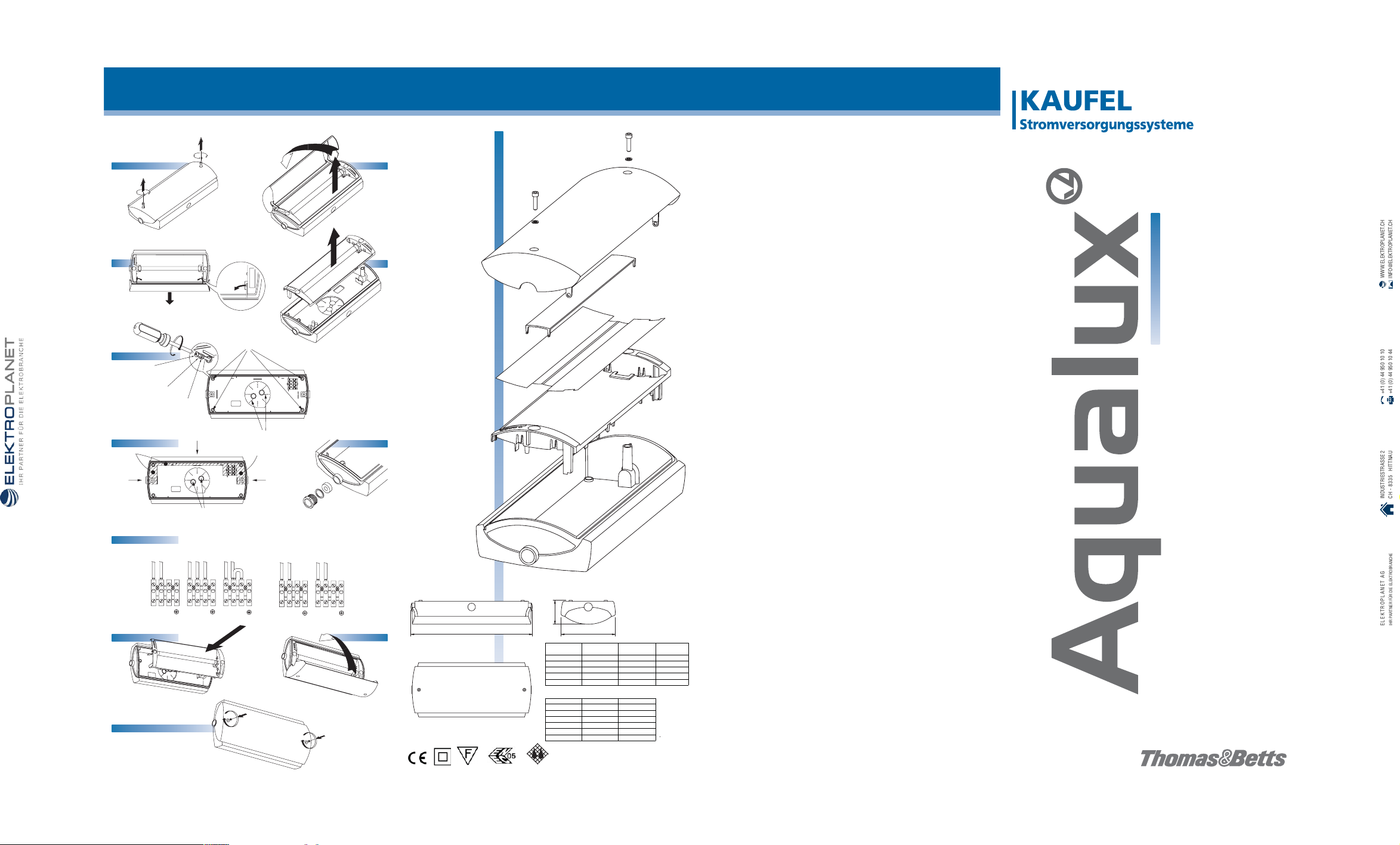
1. ÖFFNEN DER AQUALUX
1.1. Beide Innensechskantschrauben in der Haube lösen (
siehe Abb. 1
).
1.2. Haube nach oben ziehen und nach vorne kippen (
siehe Abb. 2
).
1.3. Beide Gelenkteile der Haube vorsichtig nach innen drücken und von der Leuchte entfernen (
siehe Abb. 3
).
1.4. Komponententräger geschlossen aus dem unteren Gehäuseteil herausziehen. Eventuell einen Schlitzschraubenzieher
auf der langen Seite der Leuchte zwischen den Komponententräger und den unteren Gehäuseteil stecken und Träger
heraushebeln (
siehe Abb. 4
).
2 MONTAGE AUF OBERFLÄCHE
2.1. Die vier Montagelöcher im unteren Gehäuseteil aufbohren (
siehe Abb. 5A
).
2.2. Die vier Montagelöcher auf der Montagefläche markieren und an diesen Stellen Löcher bohren.
2.3. Für die Montage des unteren Gehäuseteils 4 mm-Schrauben (
siehe Abb. 5C
) verwenden. Um den Schutzgrad zu
gewährleisten verwenden Sie bitte Schrauben, die an der Kopfunterseite flach sind. Wenn es erforderlich ist, sind
Dübel zu verwenden. Im Beutel mit Zubehörteilen befinden sich zu diesem Zweck vier Verschlussringe aus Metall
(
siehe Abb. 5D
) und vier Abdichtringe aus Gummi (
siehe Abb. 5E
).
3. MONTAGE AUF EINEM ABZWEIG- ODER VERTEILERKASTEN
3.1. In der Mitte des unteren Gehäuseteils befindet sich eine Bohrschablone mit Montagelöchern für einen Abzweig-
oder Verteilerkasten. Die Aqualux lässt sich in Stufen von je 45° zum Abzweig- oder Verteilerkasten montieren.
Die entsprechenden Löcher durchbohren (
siehe Abb. 5B
).
3.2. Eine der beiden Leitungsdurchführungen ausbrechen (
siehe Abb. 6F
) und das Anschlusskabel hindurchstecken, bevor
die Leuchte endgültig angebracht wird. Dieses Anschlusskabel darf nicht zu weit in die Leuchte hineingeschoben
werden, damit es bei der Montage der Komponenten im Innern nicht zu Montageproblemen kommt.
ACHTUNG!
Es ist für eine einwandfreie Abdichtung zu sorgen, damit der Abzweig- oder
Verteilerkasten richtig an die Fläche der Leuchte anschließt. Eventuell sollten zusätzliche
Dichtungsmittel verwendet werden. Bei der genannten Installationsart wird IP67 nicht
erreicht.
3.3. Es sollten vorhandene M4-Schrauben aus dem Abzweig- oder Verteilerkasten sowie eventuell die mitgelieferten
Dichtungsringe verwendet werden. Leuchte montieren.
4. ANSCHLUSS DER LEUCHTE
4.1. Es gibt fünf Möglichkeiten für das Einführen der Leitung: Eine Einführung auf der langen Seite, je eine auf den beiden
kurzen Seiten und zwei an der Unterseite des unteren Gehäuseteils (
siehe Abb. 6F
). Die beiden letzteren sind nur dann
geeignet, wenn die Leuchte auf einem Abzweig- oder Verteilerkasten montiert wird (
siehe Punkt 3
).
4.2. Die Aqualux besitzt drei integrierte Kabeleinführungen. Ein Beutel mit Zubehörteilen wird mitgeliefert, um für eine
einwandfreie Dichtung zu sorgen (
siehe Abb. 7
).
4.3. Die Staubkappe vom die Kabeleinführungen entfernen.
4.4. Die Zwischenwand aus Kunststoff aus Kabeleinführungen ausbrechen.
ACHTUNG!
Um eine einwandfreie Dichtung zu erreichen, ist ein Kabel mit einem Durchmesser von
mindestens 7 mm zu verwenden. Bei der Verwendung dickerer Kabel lassen sich Teile der
Innenseite des Gummizwiebelrings entfernen, damit das Kabel einwandfrei umschlossen
wird. Der maximale Kabeldurchmesser beträgt 13,4 mm. Die innere Lüsterklemme
ermöglicht die Montage von 2.5 mm
2
.
4.5. Ein ausreichendes Stück der äußeren Isolierung des Anschlussleiting entfernen. Das Kabel zuerst durch den
Druckkolben stecken, danach durch den Druckring und schließlich durch den Gummizwiebelring. Daraufhin
muss das Kabel in das untere Gehäuseteil gesteckt werden.
4.6. Den Druckkolben in den Kabeleinführung hineindrehen und festdrehen.
4.7. Die entsprechenden Adern an die Lüsterklemme anschließen. In Abb. 8 finden Sie die verschiedenen
Anschlussmöglichkeiten.
ACHTUNG!
Im unteren Gehäuseteil gibt es eine Kennzeichnung für den vorgegebenen Verlauf der
Anschlussadern, um Probleme bei der Montage der Montageplatte zu vermeiden. Wir
empfehlen, die Adern entsprechend dieser Kennzeichnung zu verlegen (
ssiehe AAbb. 66G
).
Um Anschlusleitungen durchführen zu können, müssen die Anschlüsse auf beiden Seiten der Lüsterklemme verwendet
werden.
5. SCHLIEßEN DER LEUCHTE
5.1. Den Komponententräger in das untere Gehäuseteil einsetzen. Dabei auf den Stecker der Lüsterklemme achten.
Dieser ist möglichst weit in sein Profil hineinzudrücken, damit eine einwandfreie Verbindung zur Buchse hergestellt
wird (
siehe Abb. 9
). Den Komponententräger fest andrücken.
5.2. Die Folie der Reflektorscheibe abziehen.
5.3. Die Haube nehmen, die beiden Gelenkteile vorsichtig nach innen biegen und die beiden Gelenkverbindungen in die
Schlitze der Innenkomponenten einsetzen (
siehe Abb. 10
).
5.4. Die Haube auf das untere Gehäuseteil schieben und die beiden Innensechskantschrauben festziehen (
siehe Abb.11
).
WICHTIG – BITTE ZUERST LESEN!
Vor einer Installation bzw. Inbetriebnahme ist diese Anleitung gründlich durchzulesen. Hier finden Sie wichtige Informationen
zur richtigen Installation, Nutzung, Wartung sowie Entfernung des Produkts.
Bei der Aqualux handelt es sich um eine robuste Notleuchte mit charakteristischen Eigenschaften wie Schutzart IP 67,
Isolationsklasse II sowie einer Schlagfestigkeit von IK-10.
Folgenden Vorschriften sind zu beachten:
ALLGEMEINES
1. Die Installation der Aqualux darf ausschließlich durch qualifiziertes Personal durchgeführt werden.
2. Die Installation muss gemäß VDE 0100 / IEC 60364 vorgenommen werden.
3. Dieses Produkt darf in keiner Weise verändert bzw. zu einem Verwendungszweck oder in einer Umgebung
eingesetzt werden, für die es nicht konstruiert wurde. Sollte dies dennoch ohne unsere vorherige schriftliche
Zustimmung passieren, entfallen Gewährleistung
und CE-Kennzeichnung.
4. Vor Installation und Montage ist in jedem Fall die Netzspannung auszuschalten.
5. Bei der Aqualux handelt es sich um ein Gerät mit Schutzklasse II. Der Aschluss des Erdungsleiters ist aus diesem
Grund nicht erforderlich, es sei denn, er wird für die Weiterleitung benötigt.
6. Fur Aqualux gilt IP67 nur wenn die Kabelverschraubungen verwendet werden.
INSTALLATION
Zur ordnungsgemäßen Installation der Aqualux sind die Anweisungen zu befolgen, die in der Installationsanleitung in dieser
Gebrauchsanweisung beschrieben sind.
ANSCHLUSS
Die Aqualux ist entsprechend den Angaben auf dem Typenschild an die Netzspannung anzuschließen. Das Typenschild
befindet sich an der Seite der Leuchte. Für den Anschluss verfügt die Leuchte über eine Lüsterklemme. Im Zusammenhang
mit den verschiedenen Anschlussmöglichkeiten sehen Sie bitte in die Installationsanleitung.
TESTS
Die Leuchte muss einmal järlich einem Betriebdauertest und einmal wöchentlich einem Funktionstest unterzogen werden.
Zu diesem Zweck müssen die Batterien mindestens 24 Stunden ununterbrochen aufgeladen worden sein.
SELBSTÜBERWACHUNG (/SÜ)
Die Aqualux mit dem Merkmal SÜ verfügt über einen automatischen Funktionstest. Mit dieser Funktion lässt sich die
einwandfreie Funktionsfähigkeit der Batterie, der Lampe und der Elektronik Automatisch überwachen. An der Leuchte
erscheint auf einer der amber LEDs eine Fehlermeldung, sobald eine der Komponenten nicht einwandfrei funktioniert.
24 Stunden nach Zuschaltung der Netzspannung wird der erste Betriebsdanertest durchgeführt. Einmal wöchentlich wird ein
kurzer Funktionstest von einer Minute durchgeführt. Alle 26 Wochen findet ein vollständiger Test statt. Es gibt auch die
Möglichkeit, einen Funktionstest manuell auszulösen. Dazu wird der Testschalter fünf Sekunden lang gedrückt. Bei einer
eventuellen Störung leuchtet eine der amber LEDs auf.
ZENTRALES INSPEKTIONSSYSTEM DATACENTERW (/BUS)
Leuchten, die mit dem Merkmal BUS ausgestattet sind, lassen sich mit Hilfe eines DataCenter testen. Zu diesem
Zweck verfügt die Leiterplatte der Aqualux über zwei zusätzliche Anschlüsse. Weitere Informationen finden Sie in der
DataCenterW-Betriebsanleitung, das Sie anfordern können.
An Leuchten mit BUS ist auf dem Typenschild eine sogenante CIS-Nummer angegeben. Diese Nummer spielt bei der
Kommunikation mit dem Inspektionssystem DataCenterW eine Rolle. Sie sollten diese Nummer darum auf ihrem
Positionstextbogen und ihrer Bauzeichnung oder ihrem Grundriss notieren.
INFRAROT (/IR)
Mit Hilfe einer Infrarot-Fernbedienung ist es möglich, Leuchten mit dem Bedienungsmerkmal IR zu bedienen und auszulesen,
die sich an schwer zugänglichen Orten befinden. Mit dieser Fernbedienung kan der Status der LEDs ausgelesen werden und
manuell ein Test gestartet werden. Weitere Informationen finden Sie in der Bedienungsanleitung der Fernbedienung.
BATTERIEN
Wenn die getestete Brenndauer der vorgegebenen Dauer nicht mehr entspricht, wird eine Fehlermeldung ausgelöst.
Die Batterien sind dann auszutauschen. Die Spezifikationen finden sich auf dem Schild an den
Batterien.
Nach Austausch der Batterie ist die Leuchte zurückzusetzen (“Reset”). Dazu wird der Testschalter fünf
Sekunden lang gedrückt. Es wird dann erneut ein kurzer Funktionstest durchgeführt.
LEUCHTEN MIT EVG ZUM ANSCHLUSS AN EINE
ZENTRALBATTERIEANLAGE
Diese Leuchten verfügen nicht über eine eigene Testmöglichkeit. Sie werden über ein zentrales System
getestet,
an das die Leuchte angeschlossen wird.
FRESNEL-LINSE
Die Aqualux-Haube verfügt über eine herausnehmbare Fresnel-Linse. Durch diese Linse werden die lichttechnischen
Eigenschaften optimiert. Wenn die Leuchte mit einem Piktogramm eingesetzt wird, ist die Fresnel-Linse zu entfernen.
ACHTUNG!
Damit Notbeleuchtungsanlagen ordnungsgemäß funktionieren können, muss eine
konstante (Bau-)Spannung vorhanden sein. Darüber hinaus müssen die Batterien
ausreichend geladen sein. Ist dies nicht der Fall, können die Batterien, die Lampe
oder im schlimmsten Fall die Elektronik in der Leuchte beschädigt werden.
TECHNISCHE SPEZIFIKATIONEN
/mortsleshcewV032/V42dnu)lartnezeD(zH05V032:gnunnapsssulhcsnA Gleichstrom (Zentral)
nednutS3:reuadsbeirtebnneN
LED 2W - FL 8W - LLP 11W
:epmaLredemhanfuasgnutsieL nednutS42:tiezedaL
Umgebungstemp. ta:0 °C – 25 °C tsefrutarepmethcoh)sCTVx4(hA5,1–V8,4dCiN:eirettaB NiCd 3,6V – 4,0 Ah (3 x VTD) hochtemperaturfest
NiCd 4,8V – 4,0 Ah (4 x VTD) hochtemperaturfest
II:essalkztuhcS 76PI:traztuhcS 10-KI:tiekgitsefgalhcS )lartnez(gk3,1dnu)lartnezed(gk0,2:awtethciweG mm4,31Ø.xaM–mm7Ø.niM:ressemhcrudlebaK 1170EDV/22-2-89506-NE:mroN
1. OPENING THE AQUALUX
1.1. Loosen the two socket screws in the cover (
see fig. 1
).
1.2. Lift the cover and tilt it forward (
see fig. 2
).
1.3. Carefully press the two cover hinge pins inwards and remove the cover from the fitting (
see fig. 3
).
1.4. Remove the internal mechanism in its entirety from the base. If necessary, use a flathead screwdriver as a
lever between the internal mechanism and the base (along the long side of the fitting) to remove the internal
mechanism (
see fig. 4
).
The Aqualux can either be surface mounted or mounted on a junction box/central junction box.
2. SURFACE MOUNTING
2.1 Drill the four mounting holes in the base (
see fig. 5A
).
2.2. Using the base as a template, mark the position of the four mounting holes where the Aqualux is to be mounted.
Drill the holes.
2.3. To mount the base, use 4 mm screws (
see fig. 5C
) with a round head to guarantee the IP protection rating.
If necessary, use plugs. Four metal (
see fig. 5D
) and four rubber (
see fig. 5E
) washers are included with the
accessories for this purpose.
3. MOUNTING ON A JUNCTION BOX/CENTRAL JUNCTION BOX
3.1. In the centre of the base is a drilling template indicating where to mount the Aqualux on a junction box/central
junction box. The Aqualux can be positioned at a 45° angle to the junction box/central junction box. Drill the
appropriate holes (
see fig. 5B
).
3.2. Break one of the cable conduits open (
see fig. 6F
) and guide the connecting lead through the conduit before
assembling the fitting. Avoid feeding excessive connecting lead into the fitting, otherwise you may encounter
problems installing the internal mechanism.
PLEASE NOTE:
Make certain that there is a tight seal between the surface of the fitting and the junction
box/central junction box. If necessary, use another external seal. By mounting on a
junction box the IP67 is not guaranteed.
3.3. Use the existing M4 bolts of the junction box/central junction box and, if necessary, the washers supplied.
Install the fitting.
4. CONNECTING THE FITTING
4.1. There are five ways to feed the wires through: one along the long side, one along both shorter sides and two
from the bottom of the base (
see fig. 6F
). This last option is only possible when mounting the fitting on a junction
box/central junction box (see 3).
4.2. The Aqualux has three integrated swivels. Two glands, two pressure washers and two ‘onion ring’ gaskets are
included with the accessories to ensure a tight seal (
see fig. 7
).
4.3. Remove the dust cap from the swivel conduit.
4.4. Remove the plastic seal from the swivel conduit.
PLEASE NOTE:
Use a wire with a diameter of at least 7 mm to ensure a proper seal. Parts of the interior
of the ‘onion ring’ gaskets can be removed for wires with a larger diameter to ensure a
tight seal. Wires can have a maximum diameter of 13.4 mm. The inner connector is made
for use of either flexible or massive wire of 2.5 mm
2
.
4.5. Feed the wire first through the gland, then through the pressure washer and finally through the ‘onion ring’ gasket.
The wire should then be led into the base. Ensure that a sufficient length of the connecting lead’s outermost insulation
has been removed.
4.6. Lead the swivel gland through the swivel conduit and screw into place.
4.7. Connect the required cores to the connector.
Figure 7
presents the various connection possibilities.
PLEASE NOTE:
A raised profile in the base indicates where the connection cores should be positioned to
avoid installation problems with the mounting plate. It is essential that wires follow the
path indicated by this profile (
see ffig. 66G
).
Both sides of the connector must be used to feed the connecting wires through.
CLOSING THE FITTING
5.1. Install the internal mechanism in the base. Make certain that the ‘male’ part of the connector is led through the
internal mechanism in such a way that it dovetails well with the ‘female’ part (
see fig. 9
). Press the internal
mechanism firmly into place.
5.2. Remove the foil from the reflector plate.
5.3. Replace the diffuser, carefully positioning the hinge pins, and position the two knuckles in the slots of the internal
mechanism (
see fig. 10
).
5.4. Slide the diffuser onto the base and replace the two socket screws (
see fig. 11
).
PLEASE NOTE
Carefully read the ‘Instruction Manual’ before installing or using the Aqualux. This manual provides important information
about the proper installation, use, maintenance and removal of this product.
The Aqualux is a heavy duty emergency lighting luminiare, characterised by such features as IP67protection,
insulation class II and an impact resistance of IK-10.
Please observe the following guidelines:
GENERAL
1. Aqualux should only be installed by qualified personnel.
2. Installation should be performed in accordance with the NEN 1010 / IEC 60364 standard.
3. This product may not be modified in any way whatsoever or used for a purpose or in an environment other than
for which it was designed. Failing to observe this guideline will invalidate the warranty and the CE compliance
of this product.
4. Before installing or assembling the Aqualux the supply must be isolated.
5. The Aqualux is rated with Class II insulation at it is therefore not necessary to connect an earth unless
using pass-through wiring.
6. The protective degree IP67 for the Aqualux can only be reached by use of cable glands.
INSTALLING
To properly install the Aqualux, please follow the instructions presented in the ‘Installation Instructions’.
CONNECTING
The Aqualux should be connected to a mains voltage equivalent to that indicated on the type label attached to the side of
the fitting. The fitting has a connector for this purpose. See the ‘Installation Instructions’ for the connection possibilities.
TESTING
It is recommended to test/inspect the fitting once every six months. For this purpose, the batteries must be charged for 24
hours prior to any test.
SELF-TESTING (/ZT)
The Aqualux has an automatic self-testing system. This system monitors battery operation, the lamp and the electronics.
One of the amber LEDs will indicate when one of the components is not working properly.
Twenty-four hours after turning on the mains voltage, duration of the lamp – one or three hours – will be fully tested.
Once connected to the mains voltage, the Aqualux will perform a brief one-minute function test once every seven days,
and a complete test, including duration, once every 26 weeks.
It is also possible to perform manual tests by pressing and holding the test button for five seconds. One of the amber
LEDs will light up in the event of a defect.
CENTRAL INSPECTION SYSTEM (/CIS)
Fittings equipped with CIS can be tested by means of a CIS DataCenter or PC. To this end, the Aqualux PC board has two
additional connection points. For more detailed information, please request the CIS manual.
Fittings equipped with CIS have a type label with CIS number. This number is required for the fitting to communicate with
the inspection system. For this reason, please make a note of this number on your building blueprint or map.
INFRARED (/IR)
Using an IR remote control, it is possible to read the status of and operate fittings that are installed in hard to reach
places. This remote control can ‘read’ the status of the LEDs and manually activate tests. Fittings equipped with this IR
function conduct tests according to the standard self-testing cycle. For more information, please consult the remote
control instruction manual.
CENTRAL FITTINGS
These fittings are not equipped with their own testing systems. They are tested by means of the central system to which
the fitting is connected.
BATTERIES
A fault will occur when test results for duration no longer meet the requirements indicated for the fitting. The batteries
must then be replaced. Please see the label on the batteries for the type required.
After replacing the batteries, it is possible to reset the fitting by pressing and holding the test button for five seconds.
This initiates a brief function test.
Used batteries must be recycled or disposed of as household chemical waste.
FRESNEL LENS
The Aqualux cover has a removable fresnel lens. This lens optimises the properties of light. When the fitting is used in
combination with a pictogram, the fresnel lens should be removed.
PLEASE NOTE:
Constant voltage is required and the batteries must be sufficiently charged for emergency
lighting to function properly. Failure to observe this requirement can damage the batteries,
the fluorescent tube or, in the worst-case scenario, the fitting’s electronics.
TECHNICAL SPECIFICATIONS
)metsyslartnec(CD/CAV032/V42dna)deniatnoc-fles(zH05V032:sniaM sruoh3:ymonotuA 2W-LED, 8W-FL and 11W-CL:ecnamrofreP sruoh42:emitgnigrahC
Ambient temperature (taC
°52-C°0:) )sCTVx4(hA5,1–V8,4dCiN:seirettaB NiCd 3,6V – 4,0 Ah (3 x VTD)
NiCd 4,8V – 4,0 Ah (4 x VTD)
II:yrogetacnoitalusnI 76PI:yrogetacnoitcetorP IK-10:ecnatsisertcapmI )metsyslartnec(gk3.1dna)deniatnoc-fles(gk0.2:).xorppa(thgieW mm4.31Ø–mm7Ø:retemaidelbaC 22-2-89506CEI-NE:dradnatS