Thorlux Lighting Smart External User manual

1
21LFT25430 Issue 6 PN 2307F Oct 17
Smart External
SC 14228SS - SmartScan External Programmer
INTRODUCTION TO THE SMART EXTERNAL SYSTEM
The Smart External system provides a simple, eective means
of controlling exterior luminaires independently or in groups
(zones). Signicant energy savings and reduced operating costs
may be achieved by switching due to presence detection and
daylight sensing.
SMART EXTERNAL LIGHTING
Each Smart External luminaire is equipped with a Smart Micro-sensor
and Controller, so it responds to movement and light level.
1. OCCUPANCY SENSING - Each Smart External luminaire contains
a PIR. Detection area varies - specic details for each Luminaire are
available upon request.
IP43
IP22
IP40
IP20
IP23
IP44
IP50
IP53
IP54
IP54
IP55
IP60
IP65
IP66
IP67
IP68
III
IP40
D
IK10
IP42
IP64
2. LIGHT MEASUREMENT/REGULATION – the ambient light level is
measured so that the luminaire does not operate during the hours
of daylight.
3. INFRA-RED PROGRAMMING - The Smart External Programmer
enables permanent adjustments to light levels, time delays and
switching patterns etc. Each luminaire needs to be programmed
individually and may be set to suit local conditions.
4. SMARTSCAN WIRELESS CONTROL - With the addition of an optional
plug on radio module Smart sensors can communicate through a mesh
radio network for group linking and remote energy monitoring.
THE SMART PROGRAMMER
The Smart External Programmer has six ‘touch pad’ buttons.
DISPLAY
On the rst LCD line the menu point is displayed. On the second line, the status line, the possible settings for this menu
point are shown. During a data transmission, the actual transmission status (as well as any error messages) is shown.
TECHNICAL DATA
■Dimensions : 198 x 121 x 52mm
■Power : 4-o AA/1.5V Battery (supplied)
GB - CLASS II LASER. DO NOT STARE INTO BEAM
FR - LASER DE CLASSE 2. NE PAS REGARDER LE FAISCEAU
DE - LASERKLASSE II. BITTE NICHT IN DEN STRAHL BLICKEN
SE - KLASS 2 LASER. TITTA INTE IN I LASERSTRÅLEN
ES - LASER CLASE II. NO MIRE FIJAMENTE AL RAYO
NL - KLASSE 2 LASER PRODUCT. STAAR NIET IN DE STRAAL
NO - KLASSE II LASER. STIRR IKKE INN I LYSKILDEN
PL - LASER KLASY II. NIE PATRZEC PROSTO W PROMIEN
PARAMETERS EACH OF THE FOLLOWING PARAMETERS MAY BE FINETUNED TO SUIT LOCAL
REQUIREMENTS AND CONDITIONS:
Parameter Description Range of
settings
Factory
default
settings
Canolux LED
Factory Preset
Light Level Sets the threshold at which the luminaire switches on. 6 - 200 lux 70 lux 200 lux
Time Delay Sets the period the luminaires will remain on after the last
detected movement before dimming down and switching o.
30s to 10hrs or
continuous 10 min 5 min
Security Level Sets the DALI level at which the luminaire will remain for the
‘If Vacant’ period set below. 1 -100 % DALI 10 % 30 %
If Vacant
Determines what happens at the end of the Time Delay set above.
If Vacant luminaire can be set to switch o, remain at the security
level for a preset period, or remain on continuously.
O or at minimum
for between 30s
and 10hrs or cont.
10 min Continuous
PIR
Sets the PIR for the luminaire. Normal setting is active.
May be set to inactive or O only to avoid nuisance switching.
(O only needs a Motionline signal to switch the light On).
Active / In-Active /
O Only Active Active
PIR Sensitivity May be adjusted to suit local conditions, and reduce nuisance switching. Min / 1.5 / Max 5 5
Bright-Out
Determines whether the luminaires are switched o during the day or operate
at all times. If set to Yes, the luminaire will switch o if the measured light
level is above the Bright-Out Threshold for more than 10mins. If set to No,
the luminaires will never switch o as a result of increased ambient light.
Yes / No Yes Yes
Bright-Out
Threshold
Sets the level at which the luminaires will switch o. It is set as a percentage
of the Light Level setting. (Default setting requires there to be greater than
140 lux for more than 10 minutes before the light will switch o.)
100% - 400% in
increments of 50% 200 % 400 %
Power Up
Determines what happens after a power cut or when the electrical
supply is re-connected. If lights power up On, they will switch o
if movement is not detected.
On / O On On
Hold Override Determines whether the luminaire (on Power Up or after time-out) returns
to automatic mode (No), or goes to the last manually set level (Yes). No / Yes No No
2
21LFT25430 Issue 6 PN 2307F Oct 17
PARAMETERS CONTINUED EACH OF THE FOLLOWING PARAMETERS MAY BE FINETUNED TO SUIT LOCAL
REQUIREMENTS AND CONDITIONS:
STATUS AND ERROR MESSAGES
TxD_Data: OK Transmission was correct
TxDTimeout No response from luminaire, e.g misaligned
transmission
TxD_Error Transmission was OK but error message
received - Re-try
Error_Flag LB Transmission not correct - try again Batteries low
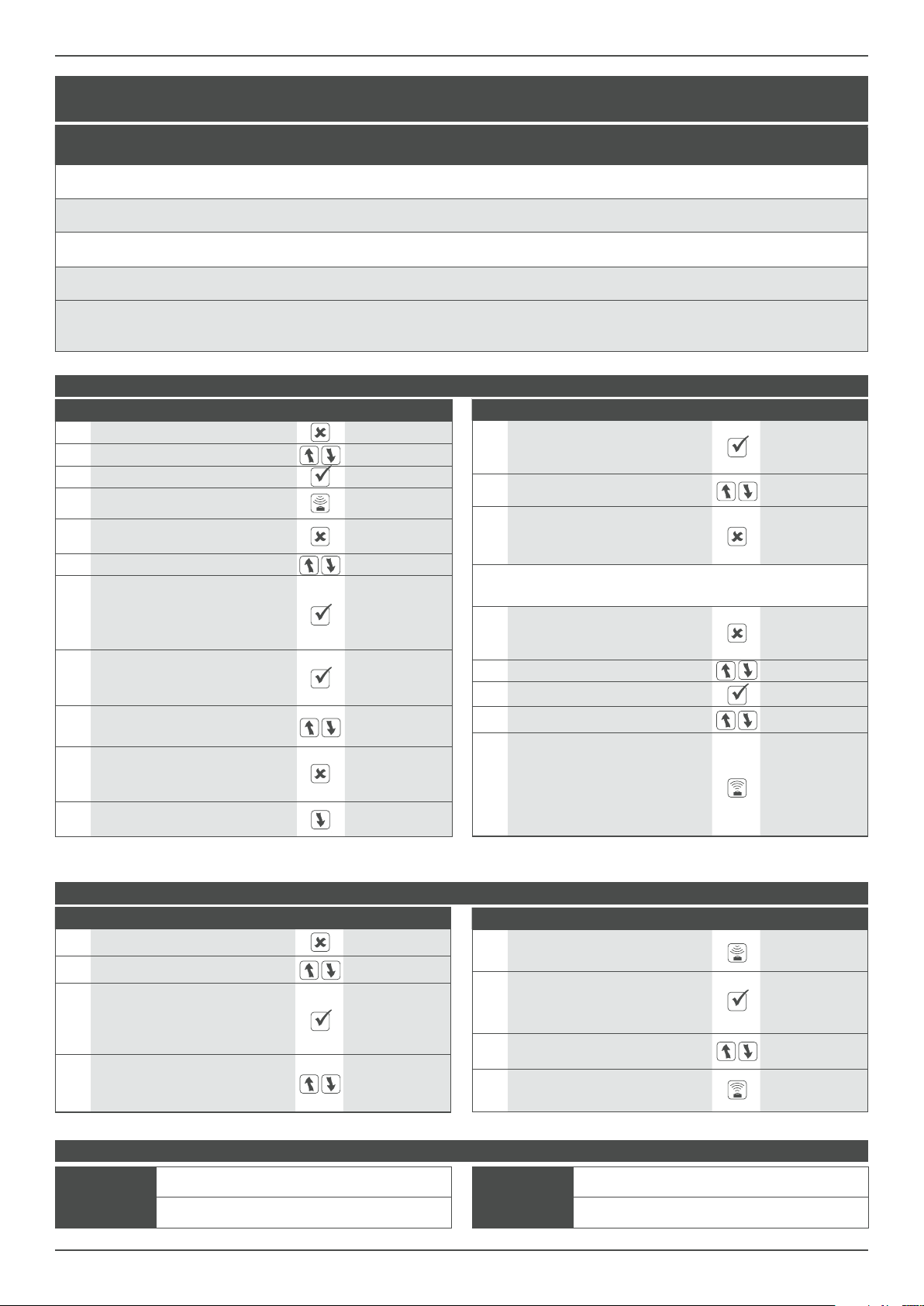
RECOMMENDED GENERAL PROGRAMMING SEQUENCE
PROGRAMMING SINGLE PARAMETERS
Check that all transmission has been conrmed by a TxD_Data: OK, message otherwise correct programming cannot be guaranteed.
Step Function Button Display
1Switch on the Smart-Programmer Smart Programmer
2Change the <parameters> setting <basic param>
3
Option name and current status are
now displayed on the top line. Second
line shows available programming
range for this parameter
Light-level: 70
6-200
4
Select parameter to be changed
(e.g. parameter bright-out from yes
to no).
Bright-out: Yes
Yes/No
Step Function Button Display
5Select Read to interrogate the actual
set value from the luminaire
Bright-out: Yes
TxD_Data OK
6
To change ‘bright-out’ option press
select button. A star in the upper corner
indicates access of program mode
Bright-out: Yes*
Yes/No
7Use scroll buttons to select required
value (eg. no)
Bright-out: No*
Yes/No
8Send will now update the chosen
value within the luminaire
Bright-out: No*
TxD_Data OK
Step Function Button Display
12
Select this parameter. Option name
and current status are now displayed
on the top line
t-delay: 20min*
30s-10hrs/cont
13 Use the scroll buttons, to select
required value (eg. 15min)
t-delay: 20min*
30s-10hrs/cont
14
To exit the setting mode press Esc.
The new selected value will now be
displayed on the rst line
t-delay: 20min
30s-10hrs/cont
15 Repeat steps from 6 to 14 until all other parameters as listed
above (i.e PIR, Bright-out, etc.) are set as required
16
When all parameters are set to the
requested values, exit, (press Esc.)
the menu <parameter>
<parameter>
17 Scroll to <downld/progr> <downld/progr>
18 Select <downld/progr> menu download all
19 Change to program all Program all
20
To congure the Smart POD with the
chosen parameters select SEND.
During the data upload, the luminaire
will switch o and after the data
transfer will operate in the automatic
mode according to the new settings.
Program all
TxD_Data: OK
Parameter Description Range of Settings
Factory
default
settings
Canolux LED
Factory Preset
Min. Lamp Sets the level below which the lamp will not dim. Has precedence over all
other settings. 1 - 100 % 10 % 10 %
Max. Lamp Sets the maximum level above which the lamp will not dim. Has precedence
over all other settings. 1 - 100 % 100 % 100 %
Burn In Time Used when new uorescent lamps are installed to run them at full output for
the rst 100 hours. O/100h O O
DALI or DSI Used to change the communication languages between the SmartScan
Sensor and the driver/ballast. DALI/DSI DALI DALI
Reection
Factor built in to compensate for diering ground colours and reection
values. Note: This is not transmitted to the SMART Pod, but is used internally
within the programmer to inuence the Light Level setting.
10 - 100 % 20 % 30 %
Step Function Button Display
1Switch on the Smart-Programmer Smart Programmer
2Change to <downld/progr> setting <downld/progr>
3Select the menu <downld/progr> download all
4Load all parameters from luminaire
into Smart-Programmer
download all
TxD.Data:OK
5All parameters are memorised in the
programmer. Exit this menu point <downld/progr>
6Change to <parameter> setting <basic param>
7
Conrm (Select). Option name and
current status are now displayed on the
top line. Second line shows available
programming range for this parameter.
Light level: 70
6-200
8
To change light level press the Select
button. A star in the upper corner
indicates access of the program mode
Light level: 70*
6-200
9Use the scroll buttons, to select the
required value (eg.65)
Light level: 55*
6-200
10
To exit the setting mode pree Esc.
The new selected value will now be
displayed on the rst line
Light level: 55
6-200
11 The next parameter may now be
selected
t-delay: 20 min
30s-10hrs/cont

3
21LFT25430 Issue 6 PN 2307F Oct 17
FUNCTION BUTTON DISPLAY
1Switch on the Smart Programmer SMART Programmer
2Scroll to the <monitors> setting <monitors>
3Select the menu <monitors> DSlmon
HOW TO DOWNLOAD THE POWER MONITORS DATA
4Scroll to ‘R-HoursPw:00:00’ R-HoursPw:00:00
Point the programmer at the
5 Smart Luminaire and press the reading......OK
(Read) button.
7Make a note of this time, then R-HoursON: 00:00
scroll to‘R-HoursON: 00:00’
Hold the Programmer in place
6 until the display reads R-HoursPw:XXXXXh
(reading.....OK)
FUNCTION BUTTON DISPLAY
Point the programmer at the
8 Smart Luminaire and press the reading......OK
(Read) button.
10 Make a note of this time, then DSIavg: 0%
scroll to the ‘DSIavg: 0%’ setting
Hold the Programmer in place
9 until the display reads R-HoursON:XXXXXh
(reading.....OK)
Point the programmer at the
11 Smart Luminaire and press the reading......OK
(Read) button.
Hold the Programmer in place
12 until the display reads DSIavg:XXX XX%
(reading.....OK)
Make a note of these values and repeat this process for every
Smart Luminaire you wish to monitor
8To turn o the Smart
Programmer, press and hold the
(Esc) button.
The Smart System records its operational usage
within the Smart sensor. This information can
be downloaded via the Smart Programmer (SC
14228SS). Each luminaire will have a dierent
energy prole depending on its location and
settings.
Average luminaire dim level is stored but
does not include ballast losses which be can
be as much as 10% of full luminaire power. A
small amount of power is also used whilst the
luminaires are o.
FUNCTION BUTTON DISPLAY
1Switch on the Smart Programmer SMART Programmer
2Scroll to the <downld/progr>
<downld/progr> setting
3Select the menu setting download all
<downld/progr>
HOW TO RESET THE POWER MONITORS
SMART POWER MONITORING
Each Smart Sensor records the following data:
HOURS POWERED TOTAL = <HoursPowr>
(0 seconds - 136 years, non-resettable)
HOURS POWERED SINCE LAST RESET =
<R-HoursPw> (0 seconds - 136 years)
HOURS LAMP ON SINCE LAST RESET =
<R-HoursON> (0 seconds - 136 years)
AVERAGE DIM LEVEL WHILST LAMPS ON =
<DSIavg> (This will record lamp dim level for
a maximum of 4,000 hours ‘on time’due to
the large amount of memory that the process
requires).
Energy monitoring is normally done over a set
period of time after the luminaires have been
commissioned. To ensure correct results the
power monitoring counters have to be reset
using the Smart Programmer (SS 14228SS)
before the trial takes place.
FUNCTION BUTTON DISPLAY
Point the programmer at the
5 Smart Luminaire and press the sending......OK
(Send) button
Repeat Step 5 for every Smart Luminaire you wish to reset
4Scroll to the reset PwrMonitor
‘reset PwrMonitor’ setting

4
21LFT25430 Issue 6 PN 2307F Oct 17
SMARTSCAN
MENU OPTIONS SMARTSCAN SENSORS
STATUS LED INDICATOR
DOWNLOAD ALL - Downloads all SmartScan settings into the Smart
programmer.
PROGRAM ALL- Uploads all settings to the SmartScan luminaire.
BUILDING ADDRESS -Identies devices that are within the same system
and forms the boundary for the wireless mesh to prevent adjacent
buildings communicating. The building address can be set between
1-254.
GROUP ADDRESS - The control group, all luminaires with the same
building address and the same group address will work together for
presence detecton and scene control. Up to 254 dierent groups can be
created in one building. The group address can be set between 1-254.
DEVICE ADDRESS- The unique device address within each group. This is
used to identify individual luminaires on the system. The device address
can be set between 1-254.
LINK ADDRESS (TX AND RX) -The link address allows presence
detection signals to be transmitted between dierent groups of
luminaires. Each group can be set to transmit or receive an independent
link address enabling occupancy in one area to keep another linked
un-occupied area illuminated. The link transmit (TX) or link receive (RX)
addresses can be set between 1-254.
READ UNIQUE DEVICE ID (UDID) - When a luminaire is connected to
the SmartScan Gateway via the mesh network it is issued with a unique
device ID number. This is used by the system to track luminaires if group
or device addresses are changed by the user. The‘UDID’ can be between
1 and 500.
RF TRANSMIT - All SmartScan luminaires are delivered with RF disabled.
RF must be enabled after addresses are set to allow communication.
RADIO LED - Radio trac indication is turned o by default to avoid user
nuisance. It can be enabled for commissioning and testing purpose.
JOIN RADIO NETWORK - Sends a join request from the luminaire to the
SmartScan Gateway. Once accepted the Gateway will issue a UDID and
request luminaire status. Note: wait 60 seconds between re-issuing join
requests.
SEND PING REQUEST - Sends a ping request to the SmartScan Gateway
to check radio communication.
LEAVE RADIO NETWORK -Send a message to the SmartScan Gateway
to remove the luminaire from the network. Once accepted the UDID is
removed from the luminaire. Note: If you remove a luminaire without
leaving the radio network the system will report the unit as faulty.
RADIO MODULE PLUGGED IN - Checks that the Smart sensor has the
SmartScan radio module connected. The answer is either Y (Yes) or N (No).
DALI TUNNEL- Enables or disables the wireless DALI tunnel (Central
control). This can be set to Di (Disable) or En (Enable).
SMART EXTERNAL SENSOR INDICATOR
SMARTSCAN INDICATORS
GENERAL -SmartScan adds wireless communication capability to Smart
and SmartScan emergency luminaires.
SmartScan uses wireless mesh technology to provide unrivalled
wireless performance, the following wavelengths are used:
868MHz in EU countries
922MHz in Australasia
The SmartScan plug on module is factory installed on
the back of the Smart, Smart High-bay and Smart External sensors.
DEFAULT SETTINGS - Each SmartScan luminaire is delivered without
any addresses set and radio (RF) communications disabled. It is
important to set addresses correctly.
LED STATUS - SmartScan luminaires provide status feedback through
various coloured LEDs on each unit. The factory default is for radio status
Indication to be disabled to avoid user nuisance. This can be enabled
using the programmer.
EVENT DEFAULT BEHAVIOUR IF ENABLED BY SMARTSCAN PROGRAMMER
RF transmitted LED OFF Blue LED - ashes once
RF received LED OFF LEDs OFF
RF inhibit LED OFF Yellow LED - ashes once every 8 seconds
Join/leave/ping net-
work request
Blue LED - ashes for a maximum
of 60 seconds
Blue LED - ashes for a maximum
of 60 seconds
Join/leave/ping
network
successful response
Smart: Green LED - ashes 10 times Smart: Green LED - ashes 10 times
Emergency: Amber LED - ashes 10 times Emergency: Amber LED - ashes 10 times
NOTE: If no response is received after 60 seconds, the LED stops ashing, and reverts
to normal display (as dened above based on device address).
Join/leave/ping
network
unsuccessful response
Smart: Red LED - ashes 10 times Smart: Red LED - ashes 10 times
Emergency: LEDs OFF Emergency: LEDs OFF
EVENT DEFAULT BEHAVIOUR
Bright-out Green LED - fast ash (1 second ON,
1 second OFF)
Permanent OFF Green LED - slow ash (1 second ON,
4 seconds OFF)
Movement detection Red LED - ashes once
IR Programmer receive Red LED - ashes 3 times
100 hour burn in Red LED - permanent ON
Motionline short circuit Red LED - fast ash (1 second ON,
1 second OFF)

5
21LFT25430 Issue 6 PN 2307F Oct 17
ESSENTIAL CONFIGURATION
Each SmartScan device requires programming with two addresses. A third device address and fourth link address is optional. Programming is carried out
using the Smart Programmer. In order to prevent areas of a building inadvertently communicating it is essential that addresses are correctly set and we
recommend they are recorded for future reference.
Enable RF communications.
Identies devices that are within
the same system and forms the
boundary for the wireless mesh
to prevent adjacent buildings
communicating.
The building address can be set
between 1-254.
The control group, all luminaires
with the same building address and
the same group address will work
together for presence detection.
Up to 254 dierent groups can be
created in one building.
The group address can be set
between 1-254.
The unique device address within
each group. This is used to identify
individual luminaires within a
group.
The device address can be set
between 1-254.
The link address allows presence
detection
signals to be transmitted
between dierent groups of
luminaires. Each group can be
set to transmit or receive an
independent link address enabling
occupancy in one area to keep
another linked un-occupied area
illuminated.
The link transmit (TX) or link
receive (RX) addresses can be set
between 1-254.
BUILDING ADDRESS GROUP ADDRESS DEVICE ADDRESS LINK ADDRESS
1. ESSENTIAL
5. ESSENTIAL
2. ESSENTIAL 3. OPTIONAL 4. OPTIONAL
= Group= Building = Device
Building 1 Building 2
1
1
11
2
2
2
3
3
3
4
4
5
5
6
6
7
2 3
1
23
BUILDING, GROUP & DEVICE ADDRESS - Example
All luminaires within groups 1-3 have their building address set
to 1, and their relevant group address set. This will ensure that
all lights in Building 1, and only Building 1, communicate within
their group, but groups do not communicate with each other.
The device address is used to identify individual luminaires on the
system when using platform 2.
BUILDING 1 BUILDING 2
By setting the building address to 2, these luminaires will not
communicate with the adjacent building. All luminaires within a
group will communicate, but groups will remain separate.

6
21LFT25430 Issue 6 PN 2307F Oct 17
FUNCTION BUTTON DISPLAY
PROGRAMMING SINGLE PARAMETERS SMARTSCAN EMERGENCY LUMINAIRES
The Smart programmer can be used to commission, test and
interrogate SmartScan emergency luminaires.
To commission emergency luminaires use LCM 10777SS and
refer to 21LFT 32418.
To perform manual testing and fault diagnosis on emergency
luminaires use the Emergency Status menu.
1Switch on the Smart Programmer
2Scroll to the <SmartScan Sensors>
<SmartScan Sensors> menu
3Select the menu download all
<SmartScan Sensors> <SmartScan only>
4Use the scroll buttons, to select link tx ad: non
the required address none/1-254
Select this parameter. Option
5 name and current status are link tx ad: non*
now displayed on the top line. none/1-254
6Use the scroll buttons, to select link tx ad: 123*
the required address none/1-254
To exit the setting mode press
(Esc). The new selected value link tx ad: 123
7will now be displayed on the none/1-254
rst line.
The (Send) button will now, link tx ad: 123
8update the chosen parameter Sending.......OK
in the Smart Luminaire
LINK ADDRESS - Example
PROGRAMMING:
All areas are set to the same unique building
address.
Each area is set to its own group address (1 to 4).
Two car park zones (1 and 3) and the lobby of
the building (4) are set to transmit link address
40.
The car park zone immediately outside the
entrance/exit (3) is set to receive link address 40.
OPERATION:
The car park zone outside the building entrance
(A) will illuminate when occupancy is detected
then switch o when vacated.
If movement is detected in any of the other car
park zones (1 and 3) the zone outside entrance
(A) will become illuminated, lighting the route
to the building.
If the luminaires in the lobby (4) detect
movement then the luminaires immediately
outside the entrance are turned on so that
anyone exiting the building will walk into a
well-lit space.
It may be desirable to set some of the
luminaires in the car park zones (1, 2 and 3) to
remain illuminated at 20% for security lighting.
The Link Address feature of SmartScan provides additional communication within a building, across dierent groups, to provide linking,
such that when one group is switched on another group can be switched on too.
EXAMPLE OF CAR PARK AND BUILDING
1
2 3
4
A
Link Transmit: 40
Link Receive: 40 Link Transmit: 40
Link Transmit: 40

7
21LFT25430 Issue 6 PN 2307F Oct 17
PROGRAMMING ALL PARAMETERS AT ONCE
Now all parameters are memorised in the Smart Luminaire
(Please Note - each luminaire can have unique parameters if required)
NOTE: RF Transmit - can be enabled or disabled from the SmartScan menu
When disabled all radio transmissions are stopped.
FUNCTION BUTTON DISPLAY
1Switch on the Smart Programmer
2Scroll to the <SmartScan Sensors>
<SmartScan Sensors> menu
3Select the menu download all
<SmartScan Sensors> <SmartScan only>
Load all the parameters from the
4 Smart Luminaire into the Smart download all
Programmer Reading..... OK
All parameters are now
5memorised in the programmer.
6Scroll to the building: 123
building setting address 1-254
To change the address press
the (Select) button. (A Star in the building: 123*
7upper corner indicates access of address 1-254
the program mode).
8Use the scroll buttons, to select building: 123*
the required address address 1-254
To exit the setting mode press
(Esc). The new selected value building: 123
9will now be displayed on the address 1-254
rst line.
10 The next parameter can now group addr: 123
be selected address 1-254
Select this parameter. Option
11 name and current status are group addr: 123*
now displayed on the top line. address 1-254
16 Once all addresses have been program all
set scroll to program all <SmartScan only>
Press the send button, program all
17 hold the programmer in place Sending..... OK
until the screen reads OK
12 Use the scroll buttons, to select group addr: 123*
the required address address 1-254
To exit the setting mode press
(Esc). The new selected value group addr: 123
13 will now be displayed on the address 1-254
rst line.
14 Repeat the steps above to set device address in each area as required.
15 Set link TX (link transmit) and link RX (link receive)
addresses as required

8
21LFT25430 Issue 6 PN 2307F Oct 17
MERSE ROAD NORTH MOONS MOAT
REDDITCH WORCS. B98 9HH ENGLAND
e-mail: thor[email protected]
Web: www.thorlux.com
☎+44 (0)1527 583200
FM 10913 EMS 532104
Australia: www.thorlux.com.au ☎ +61 (0)2 9907 1261
Deutschland: www.thorlux.de ☎ +49 (0)211 6956 0310
Ireland: www.thorlux.ie ☎ +353 (0)1 460 4608
UAE: www.thorlux.ae ☎ +971 (0)2 656 5842
GB NOTICE TO CONTRACTOR PLEASE PASS THIS LEAFLET TO THE ENDUSER.
FR A L’ATTENTION DE L’INSTALLATEUR MERCI DE TRANSMETTRE CE DOCUMENT À L’UTILISATEUR.
DE HINWEIS AN DIE MONTAGEFIRMA - BITTE GEBEN SIE DIESE INFORMATION AN IHREN KUNDEN WEITER.
IT AVVISO PER CONTRACTOR LA PREGHIAMO DI INFORMARE ILLUSTRATIVO ALLE UTENTE FINALE.
SE INFORMATION TILL ENTREPRENÖREN VÄNLIGEN VIDAREBEFORDRA DETTA INFORMATIONSHÄFTE TILL SLUTANVÄNDAREN.
ES NOTA AL CONTRATISTA POR FAVOR HAGA LLEGAR ESTE FOLLETO AL CLIENTE FINAL.
NL MEDEDELING VOOR DE AANNEMER: GEEF DEZE INFORMATIE DOOR AAN DE EIND GEBRUIKER.
N0 NOTAT TIL ELEKTRIKER VÆR VENNLIG Å GI DETTE SKRIV TIL SLUTTBRUKER.
PL INFORMACJA DLA MONTAŻYSTY PROSZĘ PRZEKAZAĆ INSTRUKCJĘ MONTAŻOWĄ DLA ODBIORCY.
Thorlux products should not be modied. Any modication
may render the product unsafe and will invalidate any Safety/
Approval marks.
MODIFICATIONSMAINTENANCE
The Smart External Programmer should not be subjected to
undue mechanical shock or extremes of temperature. Clean
only with a clean dry cloth.
This manual suits for next models
1
Table of contents


