MEDIATEK Genio 700 Installation manual

MediaTek Proprietary and Confidential. © 2022 MediaTek Inc. All rights reserved.
Unauthori ed reproduction or disclosure of this document, in whole or in part, is strictly prohibited.
Use of this document and any information contained therein is subject to the terms and conditions set forth in Exhibit 1. This document
is subject to change without notice.
Version: 0.1
Release date: 2023-03-08
Genio 700 Evaluation Kit
Hardware User Guide

MediaTek Proprietary and Confidential. © 2022 MediaTek Inc. All rights reserved. Unauthori ed reproduction or disclosure of this document, in whole or in part, is strictly prohibited.
2
Genio 700 EVK
Genio 700 E
VK
Hardware
User Guide
Version History
Version ate Author escription
0.1 2023-03-08 MTK Draft Release

MediaTek Proprietary and Confidential. © 2022 MediaTek Inc. All rights reserved. Unauthori ed reproduction or disclosure of this document, in whole or in part, is strictly prohibited.
3
Genio 700 EVK
Genio 700 E
VK
Hardware
User Guide
Table of Contents
Version History ······························································································································································ 2
Table of Contents ··························································································································································· 3
1 Overview ······························································································································································· 5
1.1 General Information ················································································································································· 5
1.2 Architecture and Block Diagram ······························································································································· 5
1.3 Feature Summary ····················································································································································· 6
2 Introduction ··························································································································································· 7
2.1 CPU (MT8390) ························································································································································ 10
2.2 Power Management IC (MT6365) ·························································································································· 10
2.3 DRAM (Micron MT53E1G32D2FW-046 IT: B) ········································································································· 10
2.4 eMMC Storage (WD SDINBDG4-64G-XI2) ·············································································································· 11
2.5 M.2 Wi-Fi/Bluetooth Module (A ureWave AW-XB468NF) ····················································································· 11
2.6 M.2 5G Module (Quectel_RM500K-CN) ················································································································· 11
3 Interfaces and Connectors ···································································································································· 12
3.1 Genio 700 EVK Board I/O Connectors ···················································································································· 12
3.2 System Power Paths ··············································································································································· 13
3.2.1 Charger Power Source ··········································································································································· 13
3.2.2 System Power ························································································································································ 14
3.2.3 5G Module Power ·················································································································································· 14
3.2.4 Raspberry Pi Power 3V3 ········································································································································ 15
3.2.5 Auto Power On by plugin of AC Adaptor ··············································································································· 15
3.3 I/O Interface ··························································································································································· 15
3.4 MicroSD Slot ··························································································································································· 18
3.5 Power and Function Key Interface ························································································································· 18
3.6 USB Device ····························································································································································· 18
3.7 USB Host ································································································································································· 18
3.8 Audio Interface (Earphone and Line Out) ··············································································································· 18
3.9 Microphones ·························································································································································· 19
3.10 MIPI DSI Interface ··················································································································································· 19
3.11 MIPI CSI Interface ··················································································································································· 19
3.12 Ethernet RGMII Interfaces ······································································································································ 19
3.13 How to Switch between DPI and Ethernet Interfaces ···························································································· 19
3.14 HDMI Port ······························································································································································· 20
3.15 Antenna ·································································································································································· 21
3.16 How to Power Up the Genio 700 EVK ···················································································································· 21
3.17 How to Reflash the Codes of Genio 700 EVK ·········································································································· 21
3.18 Debug…………………………………………………………………………………………………………………………………………………………………21
4 Camera Sub-Board ··············································································································································· 25
4.1 D2 Camera Sub-Board ············································································································································ 25
4.1.1 Key Feature and Block Diagram ····························································································································· 26
5 Power istribution ··············································································································································· 27
6 Appendix ········································································································································································ 28
6.1 Factory Reset for Camera APP disappear ············································································································· 28

MediaTek Proprietary and Confidential. © 2022 MediaTek Inc. All rights reserved. Unauthori ed reproduction or disclosure of this document, in whole or in part, is strictly prohibited.
4
Genio 700 EVK
Genio 700 E
VK
Hardware
User Guide
Exhibits 1 Terms and Conditions isclaimer ················································································································· 28
List of Figures
Figure 1-1. Genio 700 Evaluation Kit System Block Diagram ······································································································ 5
Figure 2-1. Genio 700 EVK Board System Setup ························································································································· 7
Figure 2-2. Genio 700 EVK Board I/O Overview ························································································································· 8
Figure 3-1. System Power Path ················································································································································· 13
Figure 3-2. Jumper Selection for Charger Power Source Input Path ························································································ 13
Figure 3-3. Jumper Selection for System Power ······················································································································· 14
Figure 3-4. Jumper Selection for 5G Module Power Input ······································································································· 14
Figure 3-5. Jumper Selection for Raspberry Pi Power 3V3 Input ····························································································· 15
Figure 3-6. Jumper Selection for Auto Power on by plugin of Adapter ···················································································· 15
Figure 3-7. Configure UART2 Ports ··········································································································································· 16
Figure 3-8. Flash Tool Window ················································································································································· 22
Figure 3-9. Download Port ······················································································································································· 22
Figure 3-10. Debug Port ··························································································································································· 23
Figure 3-11. UART port setting ················································································································································· 24
Figure 3-12. Log (For reference ) ·············································································································································· 24
Figure 4-1. D2 Camera Sub-Board ············································································································································ 25
Figure 4-2. D2 setup on Genio 700 EVK ··································································································································· 25
Figure 4-3. Block Diagram of D2 Camera DTB Board ················································································································ 26
Figure 5-1. Power Distribution ················································································································································· 27
Figure 6-1. Factory reset ·························································································································································· 28
List of Tables
Table 2-1. Contains in The Box ··················································································································································· 9
Table 2-1. Key Component List ··················································································································································· 9
Table 3-1. Main Board Connectors ··········································································································································· 12
Table 3-2. LED Indicators ·························································································································································· 16
Table 3-3. UART Ports ······························································································································································· 16
Table 3-4. I2C Bus ····································································································································································· 17
Table 3-5. Pin Assignments of the Raspberry Pi like I/O Connector ························································································· 17
Table 3-6. Microphone Input ···················································································································································· 19
Table 3-7. Pin Mux for DPI and Ethernet RGMII Interface ········································································································ 20
Table 3-8. SMA Antennas ························································································································································· 21

MediaTek Proprietary and Confidential. © 2022 MediaTek Inc. All rights reserved. Unauthori ed reproduction or disclosure of this document, in whole or in part, is strictly prohibited.
5
Genio 700 EVK
Genio 700 E
VK
Hardware
User Guide
1Overview
1.1 General Information
Genio 700 EVK board is an evaluation kit of MediaTek MT8390 platform, integrated with WiFi/Bluetooth (M.2 Module)
and 5G/GPS (M.2 Module), which is a high performance IoT platform with rich features.
1.2 Architecture and Block iagram
Figure 1-1. Genio 700 Evaluation Kit System Block Diagram

MediaTek Proprietary and Confidential. © 2022 MediaTek Inc. All rights reserved. Unauthori ed reproduction or disclosure of this document, in whole or in part, is strictly prohibited.
6
Genio 700 EVK
Genio 700 E
VK
Hardware
User Guide
1.3 Feature Summary
MediaTek CPU (MT8390)
MediaTek PMIC (MT6365)
4GB + 4GB LPDDR4X RAM (Micron MT53E1G32D2FW-046 IT: B)
64GB eMMC5.1 x 1 (WD SDINBDG4-64G-XI2)
2.0mm DC Jack x 1 (for 12V DC Input)
Micro SD Card Slot x 1
Push Button x 4 (Power, Reset, Download and Home Key)
LED x 4 (Power, Reset, System on and Charging Status)
4-Lane DSI x 2
eDP x 1
HDMI2.0 x 1
10/100/1000M Ethernet x 1 (Shared with DPI Signal)
USB Device Port x 1 (Micro USB Connector)
USB Host Port x 1 (Type-C USB Connector)
3.5mm Earphone Jack x 1 (with Microphone Input)
3.5mm Line Out Audio Jack x 1
Analog Microphone x 1
Digital Microphone x 2
UART Port x 3 for Trace Log with USB to UART Bridge IC (Micro USB Connector x 3)
I2C Capacitive Touch Pad
4-Data Lane CSI x 2
M.2 Slot x 2 (for A ureWave AW-XB468NF WiFi Module、AW-CB451NF WiFi Module)
40-Pin 2.54mm Pin Header x 1 (for Raspberry Pi like I/O Interface)

MediaTek Proprietary and Confidential. © 2022 MediaTek Inc. All rights reserved. Unauthori ed reproduction or disclosure of this document, in whole or in part, is strictly prohibited.
7
Genio 700 EVK
Genio 700 E
VK
Hardware
User Guide
2Introduction
Genio 700 EVK board integrates MediaTek MT8390 processor, 64bit LPDDR4X memory, eMMC, Power Management IC
(MT6365) , WiFi/BT M.2 Module and 5G M.2 Module.
The package contains a Genio 700 EVK Main board, 7” LCD panel, and a stand set for 7” LCD panel.
Figure 2-1. Genio 700 EVK Boar System Setup

MediaTek Proprietary and Confidential. © 2022 MediaTek Inc. All rights reserved. Unauthori ed reproduction or disclosure of this document, in whole or in part, is strictly prohibited.
8
Genio 700 EVK
Genio 700 E
VK
Hardware
User Guide
Figure 2-2. Genio 700 EVK Boar I/O Overview
Camera CSI1
Connector
Camera CSI0
Connector
Raspberry Pi
Connector
Earphone
Connector
Speaker
Connector
C
Jack
Battery
Connector
USB(Charger)
Connector
UART2 ebug
Connector
UART1 ebug
Connector
UART0 ebug
Connector
e P LCM
Connector
H MI Monitor
Connector
USB-C ( P)
Connector
Micro USB
Connector
RJ
-
45
Connector
PWR/RST/Home/
ownload Key
JTAG Connector
MT7921
Module
- M.2 Connector
RF ANT3
Connector
RF ANT1
Connector
RF ANT2
Connector
Micro
S
Connector
Mirco SIM
Connector
Nano SIM
Connector
LCM0
Connector
CTP0
Connector
CTP1
Connector
LCM1
Connector
5G Module
- M.2 Connector

MediaTek Proprietary and Confidential. © 2022 MediaTek Inc. All rights reserved. Unauthori ed reproduction or disclosure of this document, in whole or in part, is strictly prohibited.
9
Genio 700 EVK
Genio 700 E
VK
Hardware
User Guide
S.No
Part Number or
Marking
Item Name
escription
Quantity
1
IoT-Genio 700 EVK-P1V3 Genio 700 Main Board
1
2
Camera Board (Genio 700- CAM DTB-D1V1-
D2)
Camera Board
(D2 Version)
Camera sub-board using onsemi
AP1302 Image Sensor Processor 1
3
IMX214 Camera Module Camera Module for D2
Camera Module using SONY
IMX214 CMOS Digital Image
Sensor, preconnected to AP1302
ISP Camera Board
1
4
With Touch Panel and FFC cable
7” LCD Panel
LCM Module
1
5
M.2 WIFI6 Module
AW-XB468NF (IC: MT7921L) WIFI Module 1
6
WIFI Antenna 2
7
WIFI Antenna Cable 2
8
12V AC adaptor 1
9
AC Power cord 1
Table 2-1. Contains in The Box
Function
Mfr.
PN
Baseband Processor MediaTek MT8390AV/AZA
PMIC
MediaTek
MT6365IBW/B
Buck IC
MediaTek
MT6319LP/A
Charger (Master)
Richtek
RT9471DGQW
Charger (Slave)
Richtek
RT9759WSC
Buck for SYS
Richtek
RT6276AHGQUF
Memory
Micron
MT53E1G32D2FW
-
046 IT: B
eMMC
WD(SANDISK)
SDINBDG4
-
64G
-
XI2
Connectivity
A ureWare
AW
-
XB468NF (MT7921L Module)
LCM
SHENZHEN
STARTEK
KD070FHFID015
-
C021A V1.3 (7” LCD Panel)
Camera Module 御光視覺 WDN01A-100 with IMX214 image sensor
USB3.0 HUB IC
Texas Instruments
TUSB8020BIPHPR
Type C USB Mux IC ITE IT5205FN/BX
Ethernet PHY
Realtek
RTL8211FI
-
CG
Table 2-2. Key Component List

MediaTek Proprietary and Confidential. © 2022 MediaTek Inc. All rights reserved. Unauthori ed reproduction or disclosure of this document, in whole or in part, is strictly prohibited.
10
Genio 700 EVK
Genio 700 E
VK
Hardware
User Guide
2.1 CPU (MT8390)
MediaTek MT8390 processor integrates dual-core ARM® Cortex-A78, 2.2GH processor and six-core ARM® Cortex-A55
2.0GH MPCore processor equipped with the NEON engine offers processing power necessary to support the latest OpenOs
along with its demanding applications such as web browsing, email, GPS navigation, and games.
The features of the MT8390 processor include the following:
•Octa -Core
•2 x ARM® Cortex-A78 Operating at 2.2GH with each core 64KB L1 I-Cache, 64KB L1 D-Cache and 256KB L2 Cache
•6 x ARM® Cortex-A55 Operating at 2.0GH with each core 32KB L1 I-Cache, 32KB L1 D-Cache and 128KB Cache.
•Shared 2MB L3 Cache
•NEON Processing Engine
•ARM TrustZone Security
•DVFS Technology with Adaptive Operating Voltage from 0.55V to 0.973V
•Tensilica VP6 processor with AI Accelerator (AIA or MDLA– MediaTek Deep Learning Accelerator)
•VFGBA-1204 Package
2.2 Power Management IC (MT6365)
MediaTek MT6365 power management IC is a programmable power management IC that integrates 9 buck converters and
33 LDOs to provide all power rails required by SoC and peripherals.
MT6365 adopts the SPI interface and two SRCLKEN control pins to control buck converters, LDOs, and various drivers; it
provides enhanced safety control and protocol for handshaking with the processor MT8390.
For system management, it provides the following features,
•9 Buck Converters
•33 LDOs
•Precision voltage, temperature, and current measurement fuel gauge
•26MH External Crystal for System Clock
•32.768KH RTC Oscillator for System Timing
•Watchdog Reset
•Over-current and Thermal Overload Protection
•OVP, UVLO Function
•WFBGA-203 Package
2.3 RAM (Micron MT53E1G32 2FW-046 IT: B)
Genio 700 EVK is embedded a 4GB+4GB LPDDR4X memory with the following features,
•Dual Channels with 16-bit Data Bus Width
•Supports self-refresh/ partial self-refresh mode.
•Supports dual-rank memory device.

MediaTek Proprietary and Confidential. © 2022 MediaTek Inc. All rights reserved. Unauthori ed reproduction or disclosure of this document, in whole or in part, is strictly prohibited.
11
Genio 700 EVK
Genio 700 E
VK
Hardware
User Guide
2.4 eMMC Storage (W S INB G4-64G-XI2)
A 64GB eMMC 5.1 WD SDINBDG4-64G-XI2 is used for code and data storage, via MSDC0 interface of the baseband
processor MT8390 with 8-bit width data bus.
2.5 M.2 Wi-Fi/Bluetooth Module (AzureWave AW-XB468NF)
MediaTek MT7921L is in A ureWave AW-XB468NF M.2 Module. It supports following features.
•M.2 2230 WiFi Module with Key A-E
•MediaTek MT7921L WiFi Chip
•PCIe/USB Interface
•WiFi 802.11 a/b/g/n/ac/ax
•Dual Band 2T/2R MIMO
•Bluetooth 5.2
•Security WFA WPA/WPA2/WPA3 Personal, WPS 2.0, WAPI
•Integrated LNA, PA and T/R Switch
2.6 M.2 5G Module (Quectel_RM500K-CN)
MediaTek T700 is in Quectel RM500K-CN M.2 Module. It supports following features.
•M.2 Key-B WWAN
•USB 3.0/USB2.0
•Dual SIM Single Standby (Micro SIM x 1 + nano SIM x 1)
•5G NR SA support n1/n28/n41/n78/n79
•5G NR NSA support n41/n78/n79
•LTE-FDD support B1/B3/B5/B8/B28
•LTE-TDD support B34/B39/B40/B41
•WCDMA support B1/B8
•GNSS support GPS/GLONASS/BeiDou(COMPASS)/Galileo/QZSS

MediaTek Proprietary and Confidential. © 2022 MediaTek Inc. All rights reserved. Unauthori ed reproduction or disclosure of this document, in whole or in part, is strictly prohibited.
12
Genio 700 EVK
Genio 700 E
VK
Hardware
User Guide
3Interfaces and Connectors
3.1 Genio 700 EVK Board I/O Connectors
Interface Location Note
DC Jack CN1000 12V DC Input
System Power Indicator D1002 Green LED
Reset Indicator D3200 Green LED
System On Indicator D1003 Red LED
Charging Status Indicator D1001 Green LED
Power On Button SW3200
Download Button SW3201
Home Key Button SW3202
Reset Button SW3203
USB Device CON480 USB2.0 Port
USB3.1/DP MUX CON490 USB3.1 Port/DP Display Port(MUX)
UART0 CN3200 Debug Port
UART1 CN3201 Debug Port
UART2 CN3202 Debug Port
Micro SD Card Slot CON420
DSI J2300 7” LCM0
DSI J2400 7” LCM1
Touch CN2300 7” Touch0
Touch CN2400 7” Touch1
eDP J3700 15.6” LCM
CSI0 CN2900 Camera 0 Interface
CSI1 CN2901 Camera 1 Interface
HDMI J2500 HDMI Type-A Connector
Ethernet J3900 10/100/1000M Ethernet Transceiver
M.2 Slot Key E J4000 AW-XB468NF(MT7921L) WiFi Module
M.2 Slot Key B J3800 RM500K-CN 5G Module
Raspberry Pi like I/O J4200
JTAG J3200
Earphone Jack J2601
Line Out J2600
Battery Connector J1002
Analog Microphone MIC2702
Digital Microphone 0 MIC2700
Digital Microphone 1 MIC2701
Table 3-1. Main Boar Connectors

MediaTek Proprietary and Confidential. © 2022 MediaTek Inc. All rights reserved. Unauthori ed reproduction or disclosure of this document, in whole or in part, is strictly prohibited.
13
Genio 700 EVK
Genio 700 E
VK
Hardware
User Guide
3.2 System Power Paths
There are two power supply paths for the system. One is through a buck converter (Richtek RT6276A), which convert 12V
(DC Jack) to 4.2V (VSYS). This path supports those applications without Li-Polymer batteries.
The other is through a battery charger IC (Richtek RT9471D). This path supports those applications with Li-Polymer
batteries.
Figure 3-1. System Power Path
3.2.1 Charger Power Source
The user can choose USB type C or DC12V to power the charger ICs by J1003. Usually, any one of them can meet the
requirement for most cases.
Current Rating
Charger Power Source
3 Ampere
Figure 3-2. Jumper Selection for Charger Power Source Input Path
J1000, J1001
ME_SIP-3P
112
2
33
CN1000
Buck
RT6276A
+
-
V
BT1
BATTERY
12
12V+/-5% J1003
USB
Type C
ME_SIP-3P
112
2
33
Cha ge
RT9471D
IDJ-D47B2
IDJ-D47B2 1
3
2
4
5
6
VSYS
MediaTek Proprietary and Confidential. © 2022 MediaTek Inc. All rights reserved. Unauthori ed reproduction or disclosure of this document, in whole or in part, is strictly prohibited.
14
Genio 700 EVK
Genio 700 E
VK
Hardware
User Guide
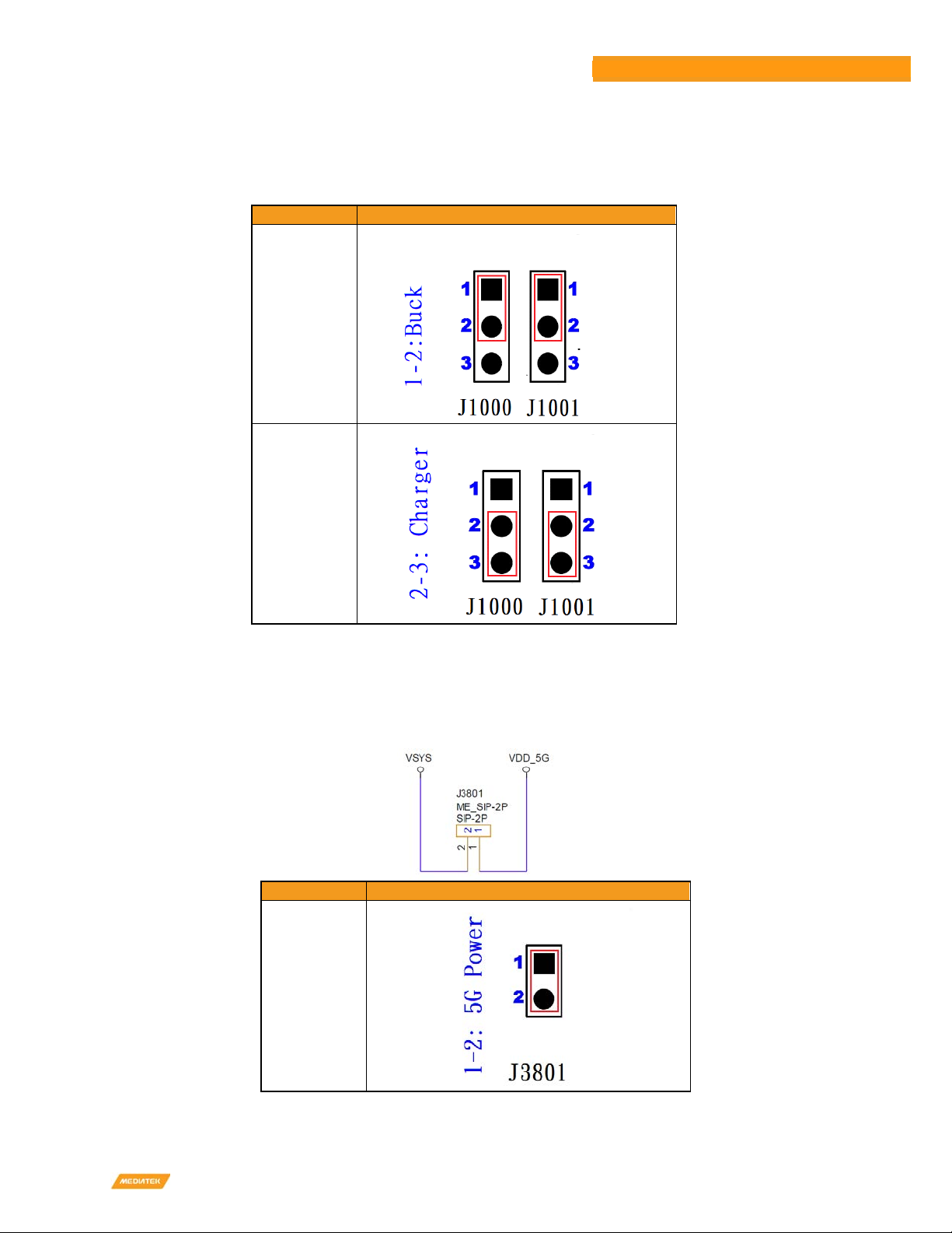
3.2.2 System Power
There are two power paths can be selected by J1000 and J1001 (at the same time) for system power VSYS.
Current Rating
System Power
6 Ampere
6 Ampere
Figure 3-3. Jumper Selection for System Power
3.2.3 5G Module Power
Before using the 5G Module, the J3801 need to plug a Jumper to get power.
Current Rating
5G Module Power
3 Ampere
Figure 3-4. Jumper Selection for 5G Mo ule Power Input

MediaTek Proprietary and Confidential. © 2022 MediaTek Inc. All rights reserved. Unauthori ed reproduction or disclosure of this document, in whole or in part, is strictly prohibited.
15
Genio 700 EVK
Genio 700 E
VK
Hardware
User Guide
3.2.4 Raspberry Pi Power 3V3
Before using the Raspberry Pi like connector, the J4201 need to plug a Jumper to get power.
Current Rating
R
aspberry Pi Power 3V3
0.3 Ampere
Figure 3-5. Jumper Selection for Raspberry Pi Power 3V3 Input
3.2.5 Auto Power On by plugin of AC Adaptor
Before using Auto Power On function by plugin of AC adaptor, the J3001 need to plug a Jumper.
Current Rating
Auto Power On by plugin of AC Adaptor
0.1 Ampere
Figure 3-6. Jumper Selection for Auto Power on by plugin of A apter
3.3 I/O Interface
LE Indicators

MediaTek Proprietary and Confidential. © 2022 MediaTek Inc. All rights reserved. Unauthori ed reproduction or disclosure of this document, in whole or in part, is strictly prohibited.
16
Genio 700 EVK
Genio 700 E
VK
Hardware
User Guide
There are four LED indicators.
LE Indicators
Location
Color
Note
System Power Indicator
D1002
Green
LED is on when system power in.
Reset Indicator D3200
Green
LED is on when reset key is pressed.
System On Indicator
D1003
Green
LED is on when system is on.
Charging Status Indicator
D1001
Red
LED is on while charging.
Table 3-2. LED In icators
UART
There are three UART (UART0 、UART1 and UART2) consoles with USB to UART Bridge ICs (FT232RL) on Genio 700 EVK
board. Users can use these consoles for debug purpose. The connectors are Micro USB type.
•Supports word Lengths from 5 to 8 bits with an optional parity bit and 1 or 2 stop bits.
•Supports baud rates from 110 bps up to 961,200 bps.
•FTDI USB to UART Bridge FT232RL
UARR Port I/O Connector Purpose
UART0 CN3200 (Micro USB) Debug
UART1 CN3201 (Micro USB) Debug
UART2 CN3202 (Micro USB) Debug
Table 3-3. UART Ports
Configure UART2 Port
Two Jumper (J4202 and J4203) to select UART2 connect to Micro USB2(CN3202) or Raspberry Pi Conn. (J4200).
Schematic escription
(1) Jumper @ 1-2, UART2 = USB
(2) Jumper @ 2-3, UART2 = Raspberry Pi
Figure 3-7. Configure UART2 Ports
I2C
•Seven I2C buses (I2C0 to I2C6)
•Supports Master Mode Only
•Adjustable clock speed for LS/FS/FS+ mode operation
•Supports 7-bit address.

MediaTek Proprietary and Confidential. © 2022 MediaTek Inc. All rights reserved. Unauthori ed reproduction or disclosure of this document, in whole or in part, is strictly prohibited.
17
Genio 700 EVK
Genio 700 E
VK
Hardware
User Guide
I2C Bus
Purpose
Note
I2C0
Capacitive Touch Controller
Goodix GS9271
Raspberry Pi I/O
I2C1
Battery Charger
RT9471D
Battery Charger
RT9759
Buck Convertor
MA5721
USB Type C MUX
IT5205FN/BX
I2C2
Audio DTB Connector
Raspberry Pi I/O
I2C3 Capacitive Touch Controller Goodix GS9271
Camera Module CSI1
I2C4
USB PD Controller
RT1715
I2C5 Camera Module CSI0
I2C6 Camera Module CSI0
Table 3-4. I2C Bus
SPI
•Support Master/Slave mode
•One chip select output.
PWM
•PWM supports old mode and FIFO mode.
•The frequency can be set from 0H to 39MH .
Raspberry Pi like I/O Interface
The pin definitions are as followings:
Pin # escription Note Pin # escription
Note
1 3.3V 2 5V
3 SDA2 GPIO60 4 5V
5 SCL2 GPIO59 6 GN
7 IO39 8 TXD2 GPIO35
9 GN 10 RXD2 GPIO36
11 IO0 12 PCM_CLK GPIO121
13 IO37 14 GN
15 IO41 16 IO111
17 3V3 18 IO40
19 SPI_MO GPIO81 20 GN
21 SPI_MI GPIO82 22 IO38
23 SPI_CLK GPIO80 24 SPI_CS GPIO79
25 GN 26 IO90
27 SDA0 GPIO56 28 SCL0 GPIO55
29 IO1 30 GN
31 IO26 32 PWM0 GPIO29
33 PWM1 GPIO30 34 GN
35 PCM_SYNC GPIO122 36 IO76
37 IO28 38 PCM_DI GPIO124
39 GND 40 PCM_DO GPIO123
Table 3-5. Pin Assignments of the Raspberry Pi like I/O Connector

MediaTek Proprietary and Confidential. © 2022 MediaTek Inc. All rights reserved. Unauthori ed reproduction or disclosure of this document, in whole or in part, is strictly prohibited.
18
Genio 700 EVK
Genio 700 E
VK
Hardware
User Guide
Note:
1. VDD_5V power can provide 5V/2A maximum but share with Camera 、HDMI 5V output.
2. EXT_3V3 power can deliver 3.3V/300mA but share with Audio DTB 、DP MUX and HDMI CEC.
3. Black words are ground pins.
4. Red words are power pins.
5. Green words are special function pins.
6. Blue words are GPIOs.
7. Pink words are pins, which multiplex with other function.
3.4 MicroS Slot
Genio 700 EVK board has one MicroSD slot. It uses MT8390 MSDC1 interface and supports following features.
•Default Speed Mode
•High Speed Mode
•SDR12 Mode
•SDR25 Mode
•SDR50 Mode
•SDR104 Mode
•DDR50 Mode
•Support 1bit/4bit SD Bus Width
3.5 Power and Function Key Interface
12V power supplies to the system from a 2.0mm DC Jack. Power-on button and Reset button on the evaluation-board to
turn on and reboot the system. Home and Download buttons make the operation easier.
3.6 USB evice
Genio 700 EVK board has one USB Device port (CON480), which can be used for download and ADB debug, with Micro USB
connector.
3.7 USB Host
Genio 700 EVK board has one USB Host port (CON490) for USB device connection, with Type-C USB connector.
3.8 Audio Interface (Earphone and Line Out)
Genio 700 EVK board provides a 3.5mm earphone jack (with a microphone input) and another 3.5mm audio jack for Line
Out (no audio amplifier is built-in).

MediaTek Proprietary and Confidential. © 2022 MediaTek Inc. All rights reserved. Unauthori ed reproduction or disclosure of this document, in whole or in part, is strictly prohibited.
19
Genio 700 EVK
Genio 700 E
VK
Hardware
User Guide
3.9 Microphones
Genio 700 EVK board was designed with one analog microphone (Merry MMA102-004) and two digital microphones
(Merry MMD300-007).
Location
Type
Note
MIC2700
Digital Microphone 1
To Processor MT8390
MIC2701
Digital Microphone 2
To Processor MT8390
MIC2702 Analog Microphone To PMIC MT6365
Table 3-6. Microphone Input
3.10 MIPI SI Interface
Genio 700 EVK board provides one 4-lane MIPI DSI interface. A StarTek LCM (KD070FHFID015-C021A) with touch pad is
provided in the box. The I2C capacitive touch controller is Goodix GT9271.
•Up to 1.2Gbps for 1-Data Lane
•Pixel format of RGB565/RGB666
•Support D-PHY version 1.1
3.11 MIPI CSI Interface
Genio 700 EVK board provides two 4-lane CSI interfaces, the CSI interface operates up to a maximum bit rate of 1.5Gbps
per lane. Camera sub-boards are connected through Molex 877159006 connector.
3.12 Ethernet RGMII Interfaces
Ethernet RGMII interface shares some pins with DPI interface. Some configurations should be done before booting up.
•Operate with an external Ethernet PHY (Realtek RTL8211FI-CG)
•Dynamically configurable to support 10/100/1000M with RGMII.
•Optional magic packet detection
•EEE (Energy Efficient Ethernet) MII signaling according to the IEEE 802.3a specification.
•RJ-45 Ethernet connector with transformer and LEDs in it.
3.13 How to Switch between PI and Ethernet Interfaces
DPI and Ethernet RGMII Interfaces share some GPIO pins. These two functions cannot exist simultaneously. Reflash code
and reboot system might be necessary when you switch between the interfaces. The ero resistors are used to switch
these two interfaces.

MediaTek Proprietary and Confidential. © 2022 MediaTek Inc. All rights reserved. Unauthori ed reproduction or disclosure of this document, in whole or in part, is strictly prohibited.
20
Genio 700 EVK
Genio 700 E
VK
Hardware
User Guide
MT8390
GPIO
Table
Ethernet
RGMII
Net Name
0R
Resistor
NM
Resistor
PI NM
Resistor
0R
Resistor
GPIO147 GBE_COL
R4401
R4404
DPI_HSYNC_DTB
R4401
R4404
GPIO148 GBE_INTR
R4407
R4410
DPI_VSYNC_DTB
R4407
R4410
GPIO131 GBE_TXD3
R4417
R4418
DPI_D0_DTB R4417
R4418
GPIO132 GBE_TXD2
R4421
R4423
DPI_D1_DTB R4421
R4423
GPIO133 GBE_TXD1
R4427
R4428
DPI_D2_DTB R4427
R4428
GPIO134 GBE_TXD0
R4431
R4432
DPI_D3_DTB R4431
R4432
GPIO135 GBE_RXD3
R4435
R4436
DPI_D4_DTB R4435
R4436
GPIO136 GBE_RXD2
R4402
R4405
DPI_D5_DTB R4402
R4405
GPIO137 GBE_RXD1
R4408
R4411
DPI_D6_DTB R4408
R4411
GPIO138 GBE_RXD0
R4413
R4415
DPI_D7_DTB R4413
R4415
GPIO139 GBE_TXC
R4419
R4420
DPI_D8_DTB R4419
R4420
GPIO140 GBE_RXC
R4425
R4426
DPI_D9_DTB R4425
R4426
GPIO141 GBE_RXDV
R4429
R4430
DPI_D10_DTB
R4429
R4430
GPIO142 GBE_TXEN
R4433
R4434
DPI_D11_DTB
R4433
R4434
GPIO143 GBE_MDC
R4403
R4406
DPI_D12_DTB
R4403
R4406
GPIO144 GBE_MDIO
R4409
R4412
DPI_D13_DTB
R4409
R4412
GPIO145 GBE_TXER
R4414
R4416
DPI_D14_DTB
R4414
R4416
GPIO146 GBE_RXER
R4422
R4424
DPI_D15_DTB
R4422
R4424
Table 3-7. Pin Mux for DPI an Ethernet RGMII Interface
3.14 H MI Port
Genio 700 EVK board provides an HDMI port, users can connect external displays. The HDMI encoder of the processors
MT8390 generate HDMITX format data base on HDMI Specification 2.0b. which support max. frequency up to 594Mh
(4096x2160p@60H 8-bit mode)
The HDMI port also supports HPD, EDID, HDCP2.3 and 3D HDMI function.
Table of contents
Other MEDIATEK Motherboard manuals

MEDIATEK
MEDIATEK Genio 700 EVK User manual

MEDIATEK
MEDIATEK Genio 1200 User manual

MEDIATEK
MEDIATEK MT7612 User manual

MEDIATEK
MEDIATEK Genio 510 User manual

MEDIATEK
MEDIATEK LinkIt 7697 HDK User manual

MEDIATEK
MEDIATEK Genio 700 EVK User manual

MEDIATEK
MEDIATEK LinkIt Smart 7688 Instruction Manual

MEDIATEK
MEDIATEK Genio 350 User manual

MEDIATEK
MEDIATEK Genio 350 Installation manual

MEDIATEK
MEDIATEK LinkIt Smart 7688 Specification sheet


