TIA WAVEJET SL 400-1744 Setup guide
WAVEJET™ SL MICROWAVE OVEN
© 2003 The Richards Corporation 25-30-51 Page TP1
December 1, 2003
COMPONENT MAINTENANCE MANUAL
WITH ILLUSTRATED PARTS LIST
WAVEJET™ SL
MICROWAVE OVEN
115 VAC, 60 Hz, 1 Phase
Part Number 400-1744
™
a division of The Richards Corporation
DESIGNERS AND MANUFACTURERS OF AIRCRAFT GALLEY INSERT EQUIPMENT
44931 FALCON PLACE lSTERLING VA 20166
WWW.TIAPRODUCTS.COM l[email protected]
(703) 471-8600 lFAX (703) 481-5007
WAVEJET™ SL MICROWAVE OVEN
COMPONENT MAINTENANCE MANUAL
WITH ILLUSTRATED PARTS LIST
25-30-51 Page ROR1/-ROR2
December 1, 2003
RECORD OF REVISIONS
REV.
NO. PAGE
INSERTED ISSUE
DATE ISSUED
BY REV.
NO. PAGE
INSERTED ISSUE
DATE ISSUED
BY
1INITIAL
RELEASE August 15,
2003 TIA
2TP, ROR1,
LEP1, LOl1,
December
1, 2003 TIA
1-8,
1001 –1010,
3001 –3006,
5002,
6002 -6005

WAVEJET™ SL MICROWAVE OVEN
COMPONENT MAINTENANCE MANUAL
WITH ILLUSTRATED PARTS LIST
25-30-51
Page ROTR1/-ROTR2
August 15, 2003
RECORD OF TEMPORARY REVISIONS
REV.
NO. PAGE
INSERTED ISSUE
DATE INSERTED
BY REMOVAL
DATE REMOVED
BY

WAVEJET™ SL MICROWAVE OVEN
COMPONENT MAINTENANCE MANUAL
WITH ILLUSTRATED PARTS LIST
25-30-51 Page SBL1/-SBL2
August 15, 2003
SERVICE BULLETIN LIST
SERVICE BULLETIN REVISION DATE BULLETIN
NUMBER NUMBER INCORPORATED
SB-MW-006 1July 31, 2003

WAVEJET™ SL MICROWAVE OVEN
COMPONENT MAINTENANCE MANUAL
WITH ILLUSTRATED PARTS LIST
25-30-51
Page LEP1
December 1, 2003
LIST OF EFFECTIVE PAGES
SUBJECT PAGE DATE SUBJECT PAGE DATE
Title Page TP1 12/1/03 Disassembly 3001 12/1/03
3002 12/1/03
Record of Revisions ROR1 12/1/03 3003 12/1/03
ROR2 Blank 3004 12/1/03
3005 12/1/03
Record of Temporary ROTR1 8/15/03 3006 Blank
Revisions ROTR2 Blank
Cleaning 4001 8/15/03
Service Bulletin List SBL1 8/15/03 4002 8/15/03
SBL2 Blank
Inspection/Check 5001 8/15/03
List of Effective LEP1 12/1/03 5002 12/1/03
Pages LEP2 8/15/03
Repair 6001 8/15/03
Table of Contents TOC1 8/15/03 6002 12/1/03
TOC2 Blank 6003 12/1/03
6004/6005 12/1/03
List of Illustrations LOl1 12/1/03
LOl2 Blank Assembly 7001 8/15/03
7002 8/15/03
Introduction INTRO1 8/15/03 7003 8/15/03
INTRO2 8/15/03 7004 8/15/03
7005 8/15/03
Leading Particulars LEP1 8/15/03 7006 8/15/03
LEP2 8/15/03
Special Tools, Fixture 9001 12/1/03
Description and 112/1/03 And Equipment 9002 Blank
Operation 212/1/03
312/1/03
412/1/03
512/1/03
612/1/03
712/1/03
812/1/03
912/1/03
10 Blank
Testing and Fault 1001 12/1/03
Isolation 1002 12/1/03
1003 12/1/03
1004 12/1/03
1005 12/1/03
1006 12/1/03
1007 12/1/03
1008 12/1/03
1009 12/1/03
1010 Blank

WAVEJET™ SL MICROWAVE OVEN
COMPONENT MAINTENANCE MANUAL
WITH ILLUSTRATED PARTS LIST
25-30-51
Page LEP2
August 15, 2003
LIST OF EFFECTIVE PAGES
SUBJECT PAGE DATE SUBJECT PAGE DATE
Illustrated Parts List 10001 8/15/03
10002 8/15/03
10003 8/15/03
10004 8/15/03
10005 8/15/03
10006 8/15/03
10007 8/15/03
10008 8/15/03
10009/
100010 8/15/03
100011/
100012 8/15/03
100013 8/15/03
100014 8/15/03
100015 8/15/03
100016 8/15/03
100017 8/15/03
100018 8/15/03
100019 8/15/03
100020 8/15/03
100021 8/15/03
100022 Blank

WAVEJET™ SL MICROWAVE OVEN
COMPONENT MAINTENANCE MANUAL
WITH ILLUSTRATED PARTS LIST
25-30-51
Page TOC1/-TOC2
August 15, 2003
TABLE OF CONTENTS
PARAGRAPH TITLE PAGE
Description and Operation..................................................................... 1
Testing and Troubleshooting................................................................. 10001
Automatic Test Requirements ............................................................... N/A
Disassembly .......................................................................................... 3001
Cleaning................................................................................................. 4001
Inspection/Check................................................................................... 5001
Repair.................................................................................................... 6001
Assembly............................................................................................... 7001
Fits and Clearances............................................................................... N/A
Special Tools, Fixtures and Equipment ................................................. 9001
Illustrated Parts List............................................................................... 10001

WAVEJET™ SL MICROWAVE OVEN
COMPONENT MAINTENANCE MANUAL
WITH ILLUSTRATED PARTS LIST
25-30-51
Page LOl1/-LOl2
December 1, 2003
LIST OF ILLUSTRATIONS
FIGURE NO. TITLE OF ILLUSTRATION PAGE NO.
1Component Layout 3
2Microwave Cooling Requirement 5
3Facia, Switch Panel 7
6001 Wiring Diagram, P/N 400-1744-01 6003/6004
10001 IPL, Wavejet SL Microwave Oven 10009/100010
10002 IPL, Wavejet Microwave Oven, 100019
Component Tray Assembly

WAVEJET™ SL MICROWAVE OVEN
COMPONENT MAINTENANCE MANUAL
WITH ILLUSTRATED PARTS LIST
25-30-51 INTRO1
August 15, 2003
INTRODUCTION
TASK 25-30-51-99F-801-A01
1. GENERAL
A. This manual has been compiled in accordance with the general requirements
set out in specification ATA 2200. It is intended for provision of such data as
is necessary for an approved repairer to return an unserviceable Wavejet SL
Microwave Oven to a serviceable condition.
TASK 25-30-51-99F-802-A01
2. LAYOUT OF MANUAL
A. This manual contains a general description and operating instructions
followed by data for maintenance, repair, disassembly and assembly of the
Wavejet SL Microwave Oven.
B. The above sections are followed by an Illustrated Parts List which gives
detailed information to requisition, store and issue replaceable parts for the
Wavejet SL Microwave Oven.
TASK 25-30-51-99F-803-A01
3. REVISION SERVICE
A. This manual will be updated as required by revisions.
B. Service Bulletins may be issued separately. Their effect on the manual will,
however, be made evident by reissue of the Service Bulletin List as
appropriate.

WAVEJET™ SL MICROWAVE OVEN
COMPONENT MAINTENANCE MANUAL
WITH ILLUSTRATED PARTS LIST
25-30-51 INTRO2
August 15, 2003
INTRODUCTION –CONT.
TASK 25-30-51-99F-804-AO1
4. MANUFACTURER
A. The Wavejet SL Microwave Oven is manufactured by:
TIA, a division of The Richards Corporation
44931 Falcon Place
Sterling, VA 20166
Telephone: (703) 471-8600
Fax: (703) 481-5007
Email: tia@tiaproducts.com
Webpage: www.tiaproducts.com
WAVEJET™ SL MICROWAVE OVEN
COMPONENT MAINTENANCE MANUAL
WITH ILLUSTRATED PARTS LIST
25-30-51
Page LP1/-LP2
August 15, 2003
LEADING PARTICULARS
1. Dimensions:
Exterior:
Model Height Width Depth
400-1744 9.8” 18.25” 13.11”*
* Microwave depth measurement with door in the closed position.
Interior:
Model Height Width Depth
400-1744 6.0” 11.0” 11.0”
2. Weight:
Microwave Oven: not to exceed 37 lbs.
3. Electrical Power Requirements
Input Voltage: 115 VAC, 1 Phase, 60 Hz (60 Hz inverter compatible)
Wattage (Input): 1200 Watts
Wattage (0utput): 600 Watts

WAVEJET™ SL MICROWAVE OVEN
COMPONENT MAINTENANCE MANUAL
WITH ILLUSTRATED PARTS LIST
25-30-51
Page 1
December 1, 2003
DESCRIPTION AND OPERATION
TASK 25-30-51-87-801-A01
1. GENERAL DESCRIPTION
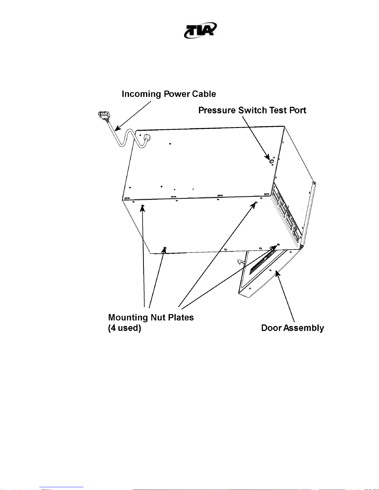
The Wavejet SL Microwave, shown in Figure 1, is a compact aviation quality microwave
oven with rugged construction and high performance reliability. The Wavejet SL is
specifically designed for aircraft use and is rated at 600 watts output. The construction and
design enhance its reliability and maintainability, and allow for easy removal from the
aircraft galley structure. The main features include stainless steel liner, simple controls,
small, lightweight and redundant overheat protection.
Wavejet SL Microwave Ovens’ features include:
• Aviation quality
• Rugged construction
• Advanced, fail-safe safety interlock system
• Tested to RTCA/DO-160D
• High performance reliability
• Altitude limit switch
• Electro-polished stainless steel interior for easy cleaning
• Uniform heating
• Overheat protection
• Solid state cooking timer, unaffected by momentary power interrupts

WAVEJET™ SL MICROWAVE OVEN
COMPONENT MAINTENANCE MANUAL
WITH ILLUSTRATED PARTS LIST
25-30-51
Page 2
December 1, 2003
Figure 1. Component Layout
(Page 1 of 2)
WAVEJET™ SL MICROWAVE OVEN
COMPONENT MAINTENANCE MANUAL
WITH ILLUSTRATED PARTS LIST
25-30-51
Page 3
December 1, 2003
Figure 1. Component Layout
(Page 2 of 2)
WAVEJET™ SL MICROWAVE OVEN
COMPONENT MAINTENANCE MANUAL
WITH ILLUSTRATED PARTS LIST
25-30-51 Page 4
December 1, 2003
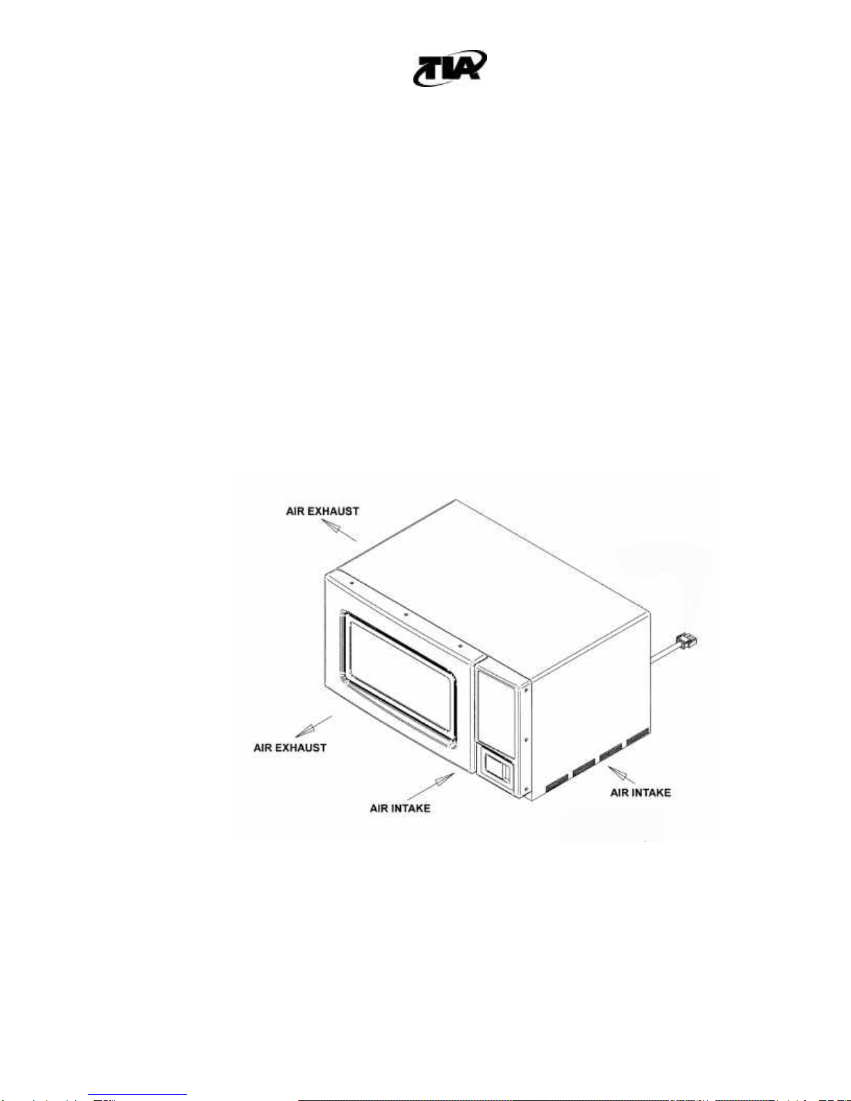
A. Ventilation Requirements
The Wavejet SL Microwave Oven is not designed to operate in a completely
enclosed compartment. Compartment doors should be open during operation to
allow for ventilation and prevent a build-up of heat and humidity.
The Wavejet SL Microwave requires unobstructed air at an inlet air temperature not
exceeding 35°C. The unit dissipates approximately 600 watts of heat via a fan
located within the unit. Cool air is drawn into the ports located in the front and right
side of the unit and warm air is ejected out the ports located in the front and left side
of the unit. For proper ventilation, the unit must have ½” clearance on each side as
shown in Figure 2. Failure to provide adequate ventilation may result in the tripping
of the Overheat Thermostats within the Microwave Oven.
Figure 2. Microwave Cooling Requirement

WAVEJET™ SL MICROWAVE OVEN
COMPONENT MAINTENANCE MANUAL
WITH ILLUSTRATED PARTS LIST
25-30-51 Page 5
December 1, 2003
B. Overheat Protection
The Wavejet SL Microwave Oven’s Overheat Protection is designed to prevent and
reduce damage from an overheat condition. The overheat protection will deactivate
the microwave oven in the event of an overheat condition or to prevent one from
occurring. There are 3 components to the overheat protection outlined below.
Pressure Switch: The pressure switch is installed in the Wavejet SL microwave oven
for reliability reasons. It is designed to deactivate the microwave at a pressure
altitude of 10,000 feet. Operating at altitudes above 10,000 may result in a
condition where the microwave overheats because the air is thin and the oven
cannot circulate sufficient air to cool itself. If the magnetron overheat thermostat
trips, the oven would have to be removed from the aircraft to have the thermostat
reset. The pressure switch is installed in this application to prevent an overheat
from occurring and avoid unit removal for an overheat due to the environmental
conditions. If the pressure switch fails, the overheat thermostat would trip and
deactivate the microwave oven.
Magnetron Overheat Thermostat: The magnetron overheat thermostat is located on
the Magnetron and will trip if the magnetron exceeds its’ normal operating
temperature. This thermostat will turn the microwave OFF and Err 1 will be
displayed. If the magnetron overheat thermostat does trip, the microwave must be
removed from the aircraft, the outer wrap removed from the microwave, and the
overheat manually reset.
Liner Overheat Thermostat: The liner overheat thermostat is located on the exterior
surface of the stainless steel oven liner and senses the temperature of the inside of
the cooking chamber of the microwave oven. The liner overheat thermostat will
deactivate the microwave oven if the cooking chamber gets too hot and will
automatically reset when the microwave cools. Over cooking food inside of the
microwave could result in this condition.
C. Installation Requirements
Mounting Hardware: There are 4 nutplates provided in the Wavejet SL for mounting
purposes. The nutplates accept SAE ¼” –28 mounting bolts. The maximum
mounting bolt depth projection into the Wavejet SL is ½ inch.
Mating Connector: Available from AMP Incorporated (V-00779)
Connector Connector Sockets (3 Required)
AMP P/N: 1-480701-0AMP P/N: 350550-6
TIA P/N: 136-0226 TIA P/N: 126-0228

WAVEJET™ SL MICROWAVE OVEN
COMPONENT MAINTENANCE MANUAL
WITH ILLUSTRATED PARTS LIST
25-30-51 Page 6
December 1, 2003
Wavejet SL Pinout
TASK 25-30-51-87-802-A01
2. OPERATION
CAUTION
NEVER OPERATE THE Wavejet®SL EMPTY. Always have food or liquid inside the
microwave when it is ON to absorb the microwave energy. Failure to do so will result
in damage to the Oven.
A. Open door by operating the paddle latch on the front of the Wavejet SL.
Note: The light inside the microwave turns ON when the microwave door is open and
during cooking.
B. Place food on center of the Teflon®cooking surface.
Note: For best results, the cooking surface must be in place on the bottom of
the oven cavity to minimize heat loss from the food during cooking.
WAVEJET™ SL MICROWAVE OVEN
COMPONENT MAINTENANCE MANUAL
WITH ILLUSTRATED PARTS LIST
25-30-51 Page 7
December 1, 2003
The cooking surface may be removed for cleaning purposes by lifting
above the four retainers and sliding it out the front of the Microwave
Oven. When reinserting the cooking surface, it must be properly
oriented. The cooking surface will not fit if inserted backwards. The
cooking surface is dishwasher safe.
C. Close door by pushing shut until latched.
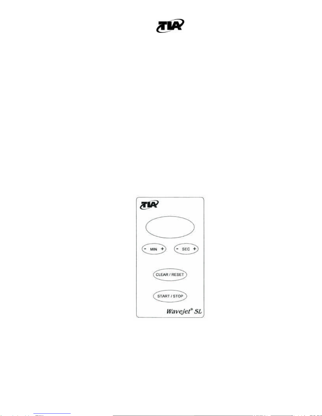
D. Display will register 00:00 except when food is cooking or when cook time is being
set. Set desired cooking time by depressing + or –on the Minute or Second button.
The displayed time will change in one minute or five-second increments, respectively.
E. Press Start/Stop button to begin the cooking cycle.
F. During the cooking cycle, 2 functions may be performed:
1. Depress Start/Stop button to turn microwave off.
2. Depress + or -buttons to increase or decrease the desired cooking time.
Figure 3. Facia/Switch Panel
G. A 5-second chime will indicate when cooking cycle is completed.

WAVEJET™ SL MICROWAVE OVEN
COMPONENT MAINTENANCE MANUAL
WITH ILLUSTRATED PARTS LIST
25-30-51 Page 8
December 1, 2003
NOTE:Upon completion of the cooking cycle, the display will register 00:00 until a new
cooking time is entered. The microwave oven will absorb power outages of less
than 1 second without interrupting the cooking cycle. Power outages lasting more
than 1 second will turn the Oven Off and may reset the Microwave time display to
00:00. Reset the time and restart Oven.
TASK 25-30-51-87-803-A01
3. Cold Weather Precautions
No special cold weather precautions are required.
TASK 25-30-51-55-801-A01
4. Storage Instructions
SUBTASK 25-30-51-001-A01
A. Preparation for Storage
(1) Ensure that the internal cavity of oven is dry and clean to prevent any
possible corrosion.
(2) Store upright in a clean, dry location where unit will not be subject to dents or
other damage.
(3) Whenever possible, units should be stored in the shipping or packing
containers originally provided by the manufacturer.
NOTE: Inserts may be stacked in accordance with standard warehouse practices. Do not
stack insert units over three items high.
(4) If inserts are to be stacked, a separator of ¼” plywood or similar protective
device is to be placed between units to insure against damage to finish or
component parts.
SUBTASK 25-30-51-55-002-A01
B. Short Duration Storage
NOTE: No special protection is required if the units are stored less than three months.

WAVEJET™ SL MICROWAVE OVEN
COMPONENT MAINTENANCE MANUAL
WITH ILLUSTRATED PARTS LIST
25-30-51 Page 9
December 1, 2003
SUBTASK 25-30-51-55-003-A01
C. Extended Duration Storage
(1) Wrap the units in water repellant material (Federal Spec. VV-P-271 or
equivalent) and enclose silica gel packages to absorb moisture.
Table of contents
Other TIA Microwave Oven manuals


