TIA WAVEJET 400-1338-02 Setup guide

WAVEJET MICROWAVE OVEN
© Copyright 2003 25-30-43 Page TP1
March 15, 2003
COMPONENT MAINTENANCE MANUAL
WITH ILLUSTRATED PARTS LIST
WAVEJET®MICROWAVE OVEN
28 VOLTS DC
Part Number 400-1338-02
Part Number 400-1409-02
Part Number 400-1746-02
Part Number 400-1860-01
a division of The Richards Corporation
DESIGNERS AND MANUFACTURERS OF AIRCRAFT GALLEY INSERT EQUIPMENT
44931 FALCON PLACE lSTERLING VA 20166
WWW.TIAPRODUCTS.COM l[email protected]
(703) 471-8600 lFAX (703) 481-5007

WAVEJET MICROWAVE OVEN
COMPONENT MAINTENANCE MANUAL
WITH ILLUSTRATED PARTS LIST
25-30-43 Page ROR1/-ROR2
March 15, 2003
RECORD OF REVISIONS
REV.
NO. PAGE
INSERTED ISSUE
DATE ISSUED
BY REV.
NO. PAGE
INSERTED ISSUE
DATE ISSUED
BY
1INITIAL
RELEASE March 15,
2003 TIA

WAVEJET MICROWAVE OVEN
COMPONENT MAINTENANCE MANUAL
WITH ILLUSTRATED PARTS LIST
25-30-43
Page ROTR1/-ROTR2
March 15, 2003
RECORD OF TEMPORARY REVISIONS
REV.
NO. PAGE
INSERTED ISSUE
DATE INSERTED
BY REMOVAL
DATE REMOVED
BY

WAVEJET MICROWAVE OVEN
COMPONENT MAINTENANCE MANUAL
WITH ILLUSTRATED PARTS LIST
25-30-43 Page SBL1/-SBL2
March 15, 2003
SERVICE BULLETIN LIST
SERVICE BULLETIN REVISION DATE BULLETIN
NUMBER NUMBER INCORPORATED
SB-MW-01 NR 5/2/01
SB-MW-02 NR 5/2/01
SB-MW-003 11/10/03

WAVEJET MICROWAVE OVEN
COMPONENT MAINTENANCE MANUAL
WITH ILLUSTRATED PARTS LIST
25-30-43
Page LEP1
March 15, 2003
LIST OF EFFECTIVE PAGES
SUBJECT PAGE DATE SUBJECT PAGE DATE
Title Page TP1 3/15/03 Disassembly 301 3/15/03
302 3/15/03
Record of Revisions ROR1 3/15/03 303 3/15/03
ROR2 Blank 304 3/15/03
305 3/15/03
Record of Temporary ROTR1 3/15/03 306 3/15/03
Revisions ROTR2 Blank 307 3/15/03
308 Blank
Service Bulletin List SBL1 3/15/03
SBL2 Blank Cleaning 401 3/15/03
402 Blank
List of Effective LEP1 3/15/03
Pages LEP2 3/15/03 Inspection/Check 501 3/15/03
502 3/15/03
Table of Contents TOC1 3/15/03 503 3/15/03
TOC2 Blank 504 Blank
List of Illustrations LOl1 3/15/03 Repair 601 3/15/03
LOl2 Blank 602 3/15/03
603 3/15/03
Introduction INTRO1 3/15/03 604/605 3/15/03
INTRO2 Blank 606/607 3/15/03
608 3/15/03
Leading Particulars LP1 3/15/03 609 3/15/03
LP2 Blank 610 Blank
Description and 13/15/03 Assembly 701 3/15/03
Operation 23/15/03 702 3/15/03
33/15/03 703 3/15/03
43/15/03 704 3/15/03
53/15/03 705 3/15/03
63/15/03 706 3/15/03
73/15/03 707 3/15/03
83/15/03 708 Blank
93/15/03
10 3/15/03 Special Tools, Fixture 901 3/15/03
And Equipment 902 Blank
Testing and Fault 101 3/15/03
Isolation 102 3/15/03 Illustrated Parts List 1001 3/15/03
103 3/15/03 1002 3/15/03
104 3/15/03 1003 3/15/03
105 3/15/03 1004 3/15/03
106 3/15/03 1005 3/15/03
107 3/15/03 1006 3/15/03
108 Blank 1007 3/15/03
1008 3/15/03
1009 3/15/03
1010 3/15/03

WAVEJET MICROWAVE OVEN
COMPONENT MAINTENANCE MANUAL
WITH ILLUSTRATED PARTS LIST
25-30-43
Page LEP2
March 15, 2003
LIST OF EFFECTIVE PAGES -Continued
SUBJECT PAGE DATE
Illustrated Parts 1011 3/15/03
List -Continued 1012 3/15/03
1013 3/15/03
1014 3/15/03
1015 3/15/03
1016 3/15/03
1017 3/15/03
1018 3/15/03
1019 3/15/03
1020/1021 3/15/03
1022/1023 3/15/03
1024 3/15/03
1025 3/15/03
1026 3/15/03
1027 3/15/03
1028 3/15/03
1029 3/15/03
1030 3/15/03
1031 3/15/03
1032 3/15/03
1033/1034 3/15/03
1035/1036 3/15/03
1035 3/15/03
1036 3/15/03
1037 3/15/03
1038 3/15/03
1039 3/15/03
1040 3/15/03
1041 3/15/03
1042 3/15/03
1043 3/15/03
1044 3/15/03
1045 3/15/03
1046 3/15/03
1047 3/15/03
1048 3/15/03
1049 3/15/03
1050 Blank

WAVEJET MICROWAVE OVEN
COMPONENT MAINTENANCE MANUAL
WITH ILLUSTRATED PARTS LIST
25-30-43
Page TOC1/-TOC2
March 15, 2003
TABLE OF CONTENTS
PARAGRAPH TITLE PAGE
Description and Operation..................................................................... 1
Testing and Troubleshooting................................................................. 101
Automatic Test Requirements ............................................................... N/A
Disassembly .......................................................................................... 301
Cleaning................................................................................................. 401
Inspection/Check................................................................................... 501
Repair.................................................................................................... 601
Assembly............................................................................................... 701
Fits and Clearances............................................................................... N/A
Special Tools, Fixtures and Equipment................................................. 901
Illustrated Parts List............................................................................... 1001

WAVEJET MICROWAVE OVEN
COMPONENT MAINTENANCE MANUAL
WITH ILLUSTRATED PARTS LIST
25-30-43 INTRO1/-INTRO2
March 15, 2003
INTRODUCTION
1. GENERAL
A. This manual has been compiled in accordance with the general requirements
set out in specification ATA 2200. It is intended for provision of such data as
is necessary for an approved repairer to return an unserviceable Wavejet
Microwave Oven to a serviceable condition.
2. LAYOUT OF MANUAL
A. This manual contains a general description and operating instructions
followed by data for maintenance, repair, disassembly and assembly of the
Wavejet Microwave Oven.
B. This is followed by an Illustrated Parts List which gives detailed information to
requisition, store and issue replaceable parts for the Wavejet Microwave
Oven.
3. REVISION SERVICE
A. This manual will be updated as required by revisions.
B. Service Bulletins may be issued separately. Their effect on the manual will,
however, be made evident by reissue of the Service Bulletin List as
appropriate.
4. MANUFACTURER
A. The Wavejet Microwave Oven is manufactured by:
TIA, a division of The Richards Corporation
44931 Falcon Place
Sterling, VA 20166
Telephone: (703) 471-8600
Fax: (703) 481-5007
Email: [email protected]
Webpage: www.tiaproducts.com

WAVEJET MICROWAVE OVEN
COMPONENT MAINTENANCE MANUAL
WITH ILLUSTRATED PARTS LIST
25-30-43
Page LOI1/-LOl2
March 15, 2003
LIST OF ILLUSTRATIONS
FIGURE NO. TITLE OF ILLUSTRATION PAGE NO.
1Component Layout 3
2Microwave Cooling Requirement 7
3Facia, Switch Panel 8
601 Wiring Diagram, P/N 400-1338-02 603/604
P/N 400-1409-02
602 Wiring Diagram, P/N 400-1860-01 605/606
603 Schematic, Inverter Board 607
604 Component Layout, Inverter PC Board 608
Assembly
1001 IPL, Wavejet Microwave Oven, DC 1020/1021
Right Hand Hinge
1002 IPL, Wavejet Microwave Oven, DC 1033/1034
Left Hand Hinge
1003 IPL, Door Assembly 1045
1004 IPL, Galley Bracket Assembly 1047

WAVEJET MICROWAVE OVEN
COMPONENT MAINTENANCE MANUAL
WITH ILLUSTRATED PARTS LIST
25-30-43
Page LP1/-LP2
March 15, 2003
LEADING PARTICULARS
1. Dimensions:
Exterior:
Model Height Width Depth
400-1338-02 13.0” 13.0” 15.76”*
400-1409-02 13.0” 13.0” 16.31”*
400-1409-02-R-N13.0” 13.0” 14.75”**
400-1409-02-L-N13.0” 13.0” 14.75”**
400-1860-01 13.0” 13.0” 16.31”*
* Microwave depth measurement includes Mounting Bracket.
** There is no mounting bracket with this model.
Interior:
Model Height Width Depth
400-1338-02 6.0” 11.0” 12.0”
400-1409-02 6.0” 11.0” 12.0”
400-1409-02-R-N6.0” 11.0” 12.0”
400-1409-02-L-N6.0” 11.0” 12.0”
400-1860-01 6.0” 11.0” 12.0”
2. Weight:
Microwave Oven with
Mounting Bracket and Connector: 35 lbs.
3. Electrical Power Requirements
Input Voltage: 28 VDC
Wattage (Input): 1000 Watts
Wattage (0utput): 500 Watts

WAVEJET MICROWAVE OVEN
COMPONENT MAINTENANCE MANUAL
WITH ILLUSTRATED PARTS LIST
25-30-43
Page 1
March 15, 2003
DESCRIPTION AND OPERATION
1. GENERAL DESCRIPTION
The Wavejet Microwave, shown in Figure 1, is a compact unit with rugged construction and
high performance reliability. It’s rated at 500 watts output and provides uniform heating.
The main features include a 4-digit LED display, an advanced safety interlock system,
computer quality cooling system for magnetron, EMI and RFI-shielded and, a solid state
cooking timer.
Wavejet Microwave Ovens’ features include:
• Aviation quality
• Rugged construction
• Advanced, fail-safe safety interlock system
• Mounting bracket for easy installation and removal (where applicable)
• Exceeds UL requirements
• Tested for RTCA/DO-160D
• High performance reliability
• Electro-polished interior for easy cleaning
• Uniform heating
• 10.75” carousel included
• Overheat protection
• Solid state cooking timer, unaffected by momentary power interrupts
The unit is available in both curved and flat front and Left Hand or Right Hand hinge
configurations depending on the preferences and requirements of the customer. Model
400-1338-02 has a flat front switch panel and door configuration. Models 400-1409-02,
400-1746-02 and 400-1860-01 have a curved front switch panel and door configuration.
A. Load Shed Circuit
This microwave has the capability for a load shed circuit. To utilize the load
shed circuit, Terminals TB1-1 and TB1-2 located on the galley bracket, must
be connected to each other for the unit to operate. If the installation does not
use this feature, the jumper (see Figure 1004, Item 80) must be installed
across TB1-1 and TB1-2 on the galley bracket or pins D and E on the input
connector for the oven to operate.

WAVEJET MICROWAVE OVEN
COMPONENT MAINTENANCE MANUAL
WITH ILLUSTRATED PARTS LIST
25-30-43
Page 2
March 15, 2003
1. The load shed circuit on microwave oven, Part Number 400-1860-01,
is protected by a 4A internal fuse.
2. The load shed circuit on microwave ovens, Part Numbers 400-1338-
02, 400-1409-02, and 400-1746-02, are not protected by an internal
fuse and carry a 2A maximum normal current.
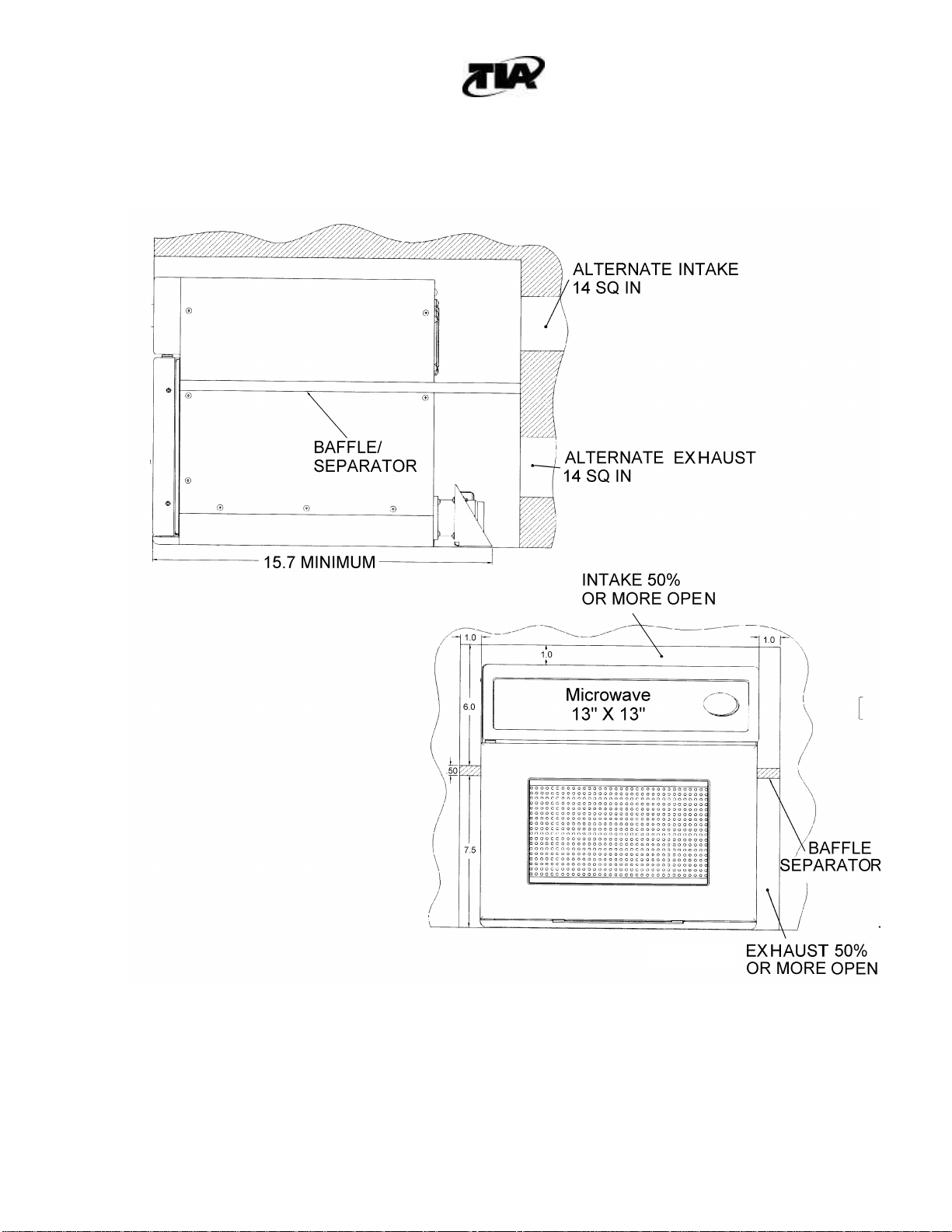
B. Ventilation Requirements
The Wavejet Microwave requires unobstructed air at the rear inlets at an inlet air
temperature not exceeding 35°C. The unit dissipates approximately 500 watts of
heat via two 3-inch diameter fans located in the top rear portion of the unit. Cool air
is drawn into the two ports located in the top rear of the unit and warm air is ejected
out the ports located in the lower portion of the unit. For proper cooling of the
microwave oven, it is strongly recommended to prevent the mixing of the cool inlet
air with the warm exhaust air. The unit has its own fans but they must have a fresh
air supply and a way to exhaust the warm air. There are three ways to do this:
1. Provide a space around the unit that is separated top to bottom with a
piece of foam or rubber (baffle) that allows the air to come in the top and
go out the bottom. Figure 2 shows the suggested installation to properly
channel the air using baffles.
2. Provide an intake at the rear and at the top of the cavity plus an exhaust
at the rear bottom. Both to be approximately 10 to 14 inches2.

WAVEJET MICROWAVE OVEN
COMPONENT MAINTENANCE MANUAL
WITH ILLUSTRATED PARTS LIST
25-30-43
Page 3
March 15, 2003
3. Provide good circulation behind the unit with a separate fan that would
both supply fresh air for the intake and exhaust the warm air.
C. Overheat Protection
The Wavejet Microwave incorporates Overheat Protection to deactivate the
microwave in the event of an overheat condition or to prevent an overheat
from occurring. There are 4 components to the overheat protection outlined
below.
Altitude Switch: The altitude switch prevents the microwave from operating
when a loss of cabin pressure has occurred. The altitude switch turns the
microwave OFF when the cabin pressure exceeds 10,000 feet. If the altitude
switch failed to open when the pressure exceeded 10,000 feet, the
microwave might overheat and result in tripping one or more of the following
thermostats.
High Voltage Transformer Overheat Thermostat –This Overheat Thermostat
is located within the high voltage transformer and turns power OFF when the
transformer exceeds its normal operating temperature. The overheat
automatically resets when the transformer cools down. The overheat is part
of the power supply assembly and is not field replaceable.
Magnetron Overheat Thermostat –This Overheat Thermostat is located on
the Magnetron and will trip if the magnetron exceeds its’ normal operating
temperature. This thermostat will turn the microwave OFF. If the magnetron
overheat thermostat does trip, the microwave must be removed from the
aircraft, the outer wrap removed from the microwave, and the overheat
manually reset.
Liner Overheat Thermostat –This Overheat Thermostat is located on the
exterior surface of the stainless steel oven liner and senses the temperature
of the inside of the cooking chamber of the microwave oven. The liner
overheat thermostat will deactivate the microwave oven if the cooking
chamber gets too hot and will automatically reset when the microwave cools.

WAVEJET MICROWAVE OVEN
COMPONENT MAINTENANCE MANUAL
WITH ILLUSTRATED PARTS LIST
25-30-43
Page 4
March 15, 2003
Figure 1. Component Layout (Page 1 of 4)
Model 400-1338-02-L Shown

WAVEJET MICROWAVE OVEN
COMPONENT MAINTENANCE MANUAL
WITH ILLUSTRATED PARTS LIST
25-30-43
Page 5
March 15, 2003
Figure 1. Component Layout (Page 2 of 4)
Model 400-1860-01 Shown

WAVEJET MICROWAVE OVEN
COMPONENT MAINTENANCE MANUAL
WITH ILLUSTRATED PARTS LIST
25-30-43
Page 6
March 15, 2003
Figure 1. Component Layout (Page 3 of 4)
Model 400-1338-02-L Shown

WAVEJET MICROWAVE OVEN
COMPONENT MAINTENANCE MANUAL
WITH ILLUSTRATED PARTS LIST
25-30-43
Page 7
March 15, 2003
Figure 1. Component Layout (Page 4 of 4)
Model 400-1338-02-L Shown
WAVEJET MICROWAVE OVEN
COMPONENT MAINTENANCE MANUAL
WITH ILLUSTRATED PARTS LIST
25-30-43 Page 8
March 15, 2003
Figure 2. Microwave Cooling Requirement
(Dimensions are in inches)

WAVEJET MICROWAVE OVEN
COMPONENT MAINTENANCE MANUAL
WITH ILLUSTRATED PARTS LIST
25-30-43 Page 9
March 15, 2003
2. OPERATION
CAUTION: Always have food or liquid in the microwave when it is ON
to absorb the microwave energy.
A. Push door button on facia/switch panel to open microwave door.
NOTE: The light inside the microwave comes ON when the microwave door is
open and during cooking.
B. Slide food into microwave.
C. Close door by pushing firmly shut until latched.
NOTE: Microwave oven will not work with door open. It must be closed.
D. Set desired cooking time by depressing + button. The time will appear on the
display in one second increments. Depress and hold the button and timer will
accelerate.
E. Press Start/Stop button to begin cooking cycle.
Figure 3. Facia/Switch Panel
(P/N 400-1338-02-L Shown)
NOTE: Curved front (400-1409-02, 400-1746-02, 400-1860-01) and flat front
(400-1338-02) facia/switch panels are identical in button placement.
Only the shape of the panel is different.
F. During cooking cycle, you can perform 2 functions:
1. Depress Start/Stop button to turn microwave off.
2. Depress + or –button to increase or decrease the cooking time.

WAVEJET MICROWAVE OVEN
COMPONENT MAINTENANCE MANUAL
WITH ILLUSTRATED PARTS LIST
25-30-43 Page 10
March 15, 2003
G. A chime will sound to indicate the completion of the cooking cycle.
NOTE: Upon completion of the cooking cycle, the display will
register 00:00 until a new cooking time is entered. The
microwave oven will absorb power outages of short duration
(less than 15 seconds). When the power drops, the oven
will stop if operating but the display will retain the cooking
time. When the power returns, the oven will return to
operation.
3. Cold Weather Precautions
No special cold weather precautions are required.
4. Storage Instructions
A. Preparation for Storage
(1) Ensure that the internal cavity of oven is dry and clean to prevent any
possible corrosion.
(2) Store upright in a clean, dry location where unit will not be subject to dents or
other damage.
(3) Whenever possible, units should be stored in the shipping or packing
containers originally provided by the manufacturer.
NOTE: Inserts may be stacked in accordance with standard warehouse practices. Do not
stack insert units over three items high.
(4) If inserts are to be stacked, a separator of ¼” plywood or similar protective
device is to be placed between units to insure against damage to finish or
component parts.
B. Short Duration Storage
NOTE: No special protection is required if the units are stored less than three months.
C. Extended Duration Storage
(1) Wrap the units in water repellant material (Federal Spec. VV-P-271 or
equivalent) and enclose silica gel packages to absorb moisture.
This manual suits for next models
5
Table of contents
Other TIA Microwave Oven manuals


Popular Microwave Oven manuals by other brands


Panasonic
Panasonic NN-GM342WZPE Operating instruction and cook book

Orava
Orava Miwa Inox instruction manual

Jenn-Air
Jenn-Air JMV8186AAB installation instructions

Panasonic
Panasonic NN-CD87KS manual

Samsung
Samsung CE1350L Owner's instructions and cooking guide

Whirlpool
Whirlpool WMC30516AB Use and care guide


