Tianjin Key-Disp KD68C User manual


Catalog
Product Name and Model............................................................................... 1
Specifications.................................................................................................. 1
Appearance and Size....................................................................................... 1
Function Summary and Button Definition....................................................... 2
◆Function Summary................................................................................2
◆Button Definition.................................................................................. 2
Install Instructions........................................................................................... 2
General Operation.......................................................................................... 3
◆Switching the eBike System On/Off...................................................... 3
◆Display Interface................................................................................... 3
◆Speed regulation...................................................................................3
◆Assistance Level Selection.....................................................................4
◆Switching the Lighting On/Off...............................................................3
◆Power Indication...................................................................................4
◆Error Code Indication............................................................................5
General Settings.............................................................................................. 5
◆Trip Distance Clearance........................................................................ 6
◆Unit km/mi Conversion.........................................................................6
◆Wheel Diameter Settings...................................................................... 7
◆Speed-limit Settings..............................................................................7
◆Battery Power Bar Settings................................................................... 8
Personalized Parameter Settings.....................................................................8
◆Power Assistance Level Settings........................................................... 9
Power Assistance Level Option.......................................................... 9
PAS Ratio Settings.............................................................................. 10
◆Controller Over-Current Cut Settings.................................................... 10

◆Backlight Contrast Settings................................................................... 11
◆Power-on Password Settings.................................................................11
Power-on Password Enable/Disable...................................................11
Power-on Password Modify............................................................... 12
◆Exit Settings.......................................................................................... 12
Factory Reset.................................................................................................. 13
Quality Assurance and Warranty Scope...........................................................13
Connection Layout.......................................................................................... 14
Operation Cautions......................................................................................... 14
1
Product name and model
Intelligent LCD display of eBike; model: KD68C.
Specifications
●24V/36V/48V Power Supply
●Rated working current: 10mA
●The maximum working current: 30mA
●Off leakage current: <1uA
●The supply controller working current: 50mA
●Working temperature:-20℃~ 60℃
●Storage temperature: -30℃~ 70℃
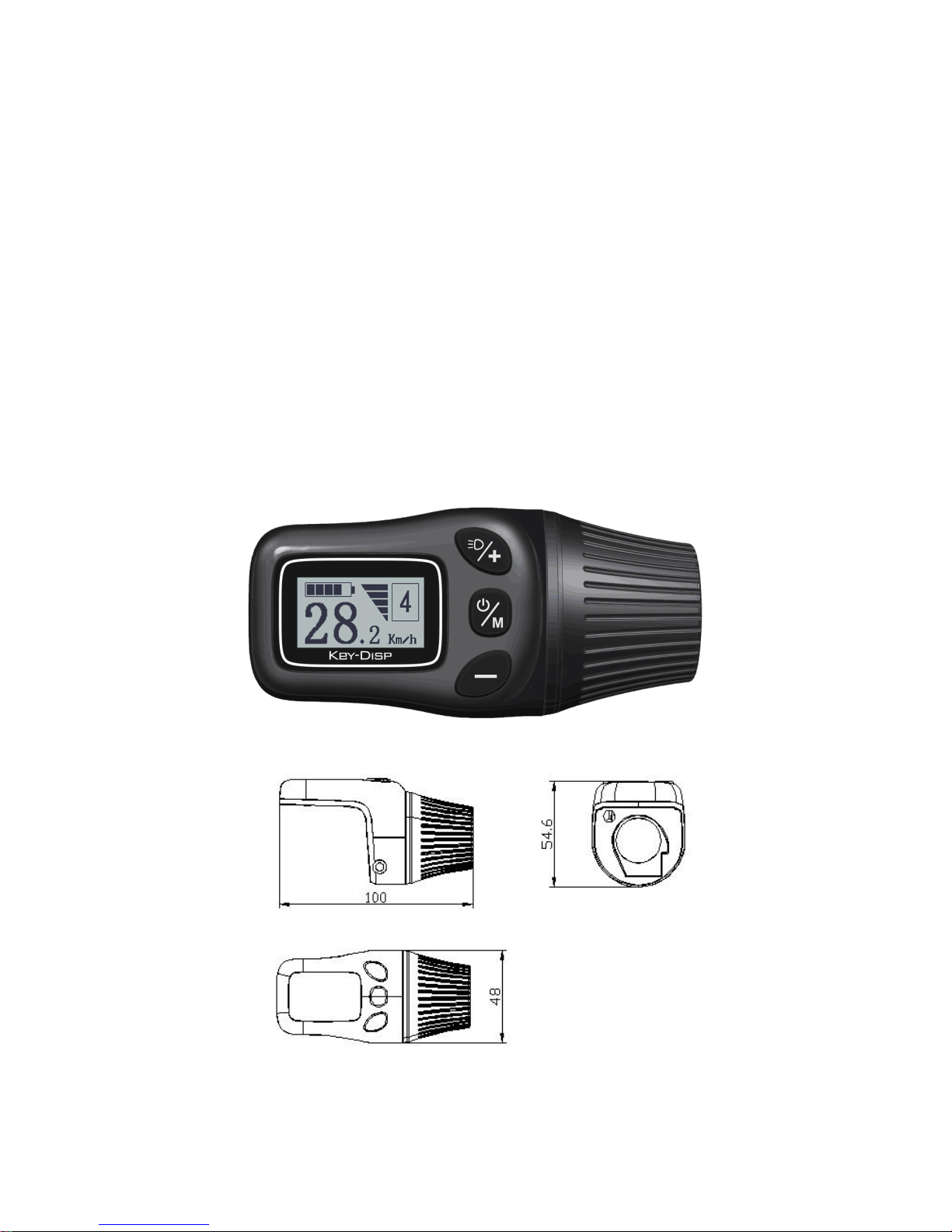
Appearance and Size
Display appearance and dimension figure (unit: mm)

2
Function Summary and Button Definition
◆Function Summary
KD21C can provide a lot of functions to fit the users’ needs. The
indicating contents as shown follows,
●Battery level indicator
●Motor output indication
●Assistance level indication
●Speed indication
●Trip time
●Trip distance and total distance
●The lighting On/Off
●Error code indication
●Various Parameters Settings(wheel diameter, speed limit, battery
level bar, controller current limit, password enable, etc.)
●Recover Default Settings
◆Button Definition
There are three buttons ( , , ) on the KD68C display
that represented by the following functions respectively: MODE, UP,
DOWN.
Install Instructions
KD68C are applicable to fixing on the right or left side of the
handlebar corresponding to the handle, pay attention to adjusting the
display screen fit to the visual. Under the circumstances of electric
scooter (bicycle) power off, link the display-side adapter and the switch
wiring to finish installation of meter.

3
General Operation
◆Switching the eBike System On/Off
To switch on the eBike system, hold the MODE button for 2s.
In the same way to hold the MODE button for 2s again, the eBike
system will be switched off.
When switching off the eBike system the leakage current is less
than 1 uA.
■When parking the eBike for more than 10 minutes, the eBike system
switches off automatically.
◆Display Interface
After switching on the eBike system, the display shows current
speed .
To change the indicated information, press the MODE button to
show in turn as below: Current Speed (Km/h) → Trip Distance (Km)
→ODO (Km)→Trip Time (Hour) → Average Speed (Km/h) → Maximum
Speed (Km/h) →Current Speed (Km/h).Each state displays for 3s,
and then automatically returns to the state of current speed.
Display Interface
◆Speed regulation
Turn the handle of KD68C can adjust the speed of electric
scooter (bicycle).

4
◆Assistance Level Selection
press the UP/DOWN to increase or decrease until the desired
assistance level is displayed. The default power ranges from level “1”
to level “3”. Level “1” is the minimum power. Level “3” is the maximum
power. The default value is level “1”.
Assistance Level “3”
◆Switching the Lighting On/Off
To switch on the display backlight and headlight of the eBike, hold
the UP button for 2s.
In the same way to hold the UP button for 2s again, the backlight
and the headlight will be switched off.
Switch On/Off the Lighting
◆Power indication
Through the display can know the power of the motor. The display
is shown in the figure below, each grid represents the power of 60W.

5
power of the motor
◆Error Code Indication
If there are errors about the electronic control system, the error code
will appear automatically. The messages of the error code refer to
Attached list 1.
Error Code Indication
■Only the error has been resolved can exit the error code
indication, the scooter (bike) will not be able to travel after the error.
General Settings
After the eBike system is switched on, to access general settings
menu, hold both UP and DOWN button for 2 s.
Press Up or DOWN button to select the content, press MODE to
confirm the corresponding settings.
6
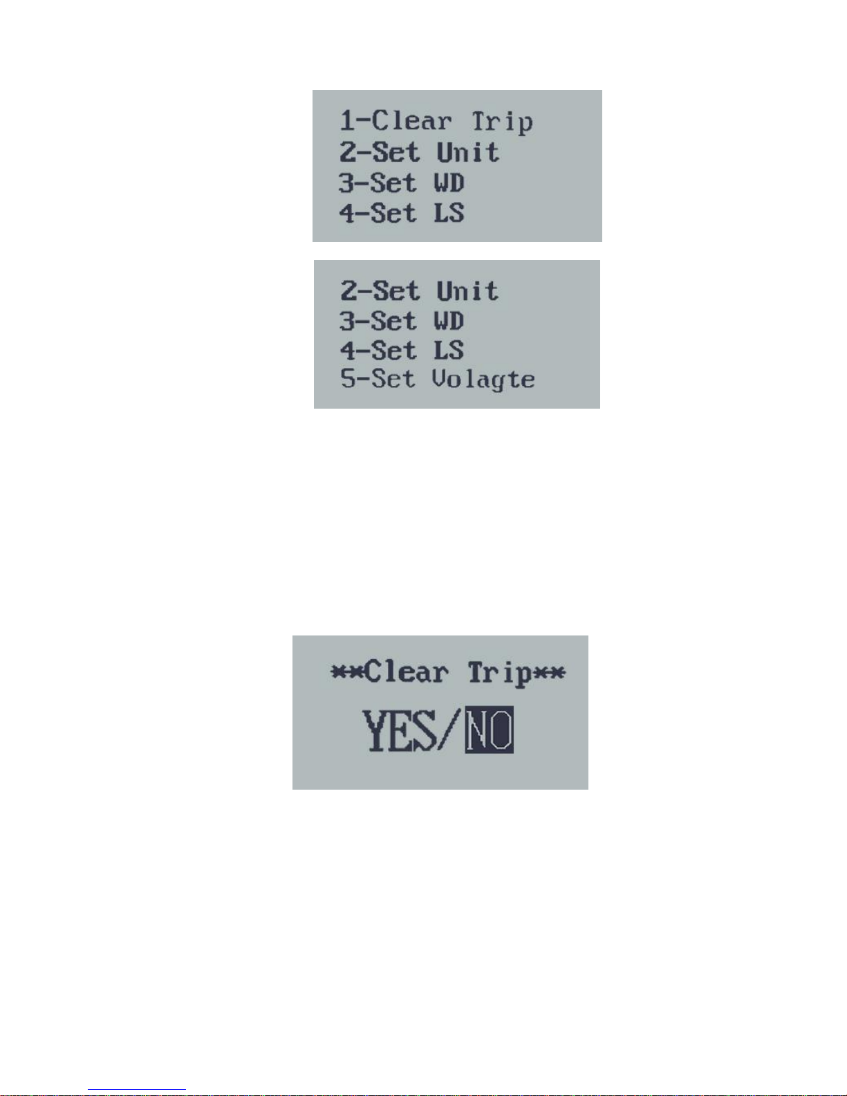
General Selection Settings Interface
◆Trip Distance Clearance
Clear Trip represents single trip distance clearance. Press UP or
DOWN button to choose YES or NO to clear the trip distance. The
default is NO. If you choose YES and press MODE button to confirm the
option, the display will show OK and return to the general selection
settings interface. Otherwise the display will return to the general
selection settings interface directly.The default is NO.
Trip distance clearance
◆Unit Mi/KM Conversion
Set Unit represents unit settings. To convert unit, press UP/DOWN to
increase or decrease until the desired setting is displayed.
To store a changed setting, press MODE button to access trip distance
clearance settings and the display will show OK then returns to general
selection settings interface. The default unit is Metric.

7
Mile and Kilometer Conversion Settings Interface
◆Wheel Diameter Settings
Set WD represents wheel diameter settings. Electable values are
16, 18, 20, 22, 24, 26, 700C and 28. Default diameter is 6 inch.
To change basic settings, press UP/DOWN to increase or
decrease until the desired value is displayed. To store a
changed setting, press MODE button and the display will show OK
then returns to general selection settings interface.
Wheel Diameter Settings Interface
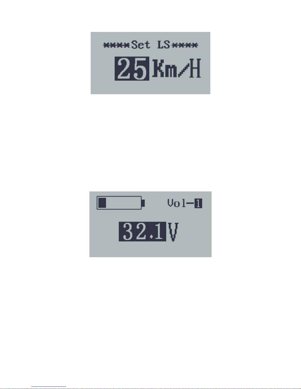
◆Speed-limit Settings
Set LS represents limit speed settings. Limit speed range is
12Km/h to 40Km/h. Limit speed default value is 25Km/h.
To change basic settings, press UP/DOWN to increase or
decrease until the desired value is displayed.To store a changed
setting, press MODE button and the display will show OK then
returns to general selection settings interface.
8
Limit Speed Settings Interface
◆Battery Power bar Settings
VOL represents voltage settings. Each bar represents a voltage
value. 5 bars voltage values must be entered one by one. For example,
VOL 1 is the first bar voltage value, the default value is 31.5V. To set
battery power bar, press UP/DOWN to increase or decrease the number.
To store a changed setting and access the second bar, press MODE
button.By analogy,after 5 bars voltage values is entered, hold MODE to
confirm and return to the previous menu.
Battery Power Bar Settings
Personalized Parameter Settings
Hold UP and DOWN button more than 2 seconds to enter general
settings, then use the same manner to enter personalized parameter
settings selection interface. Press UP or DOWN button to choose the
personalized parameter settings items, then press MODE button to enter
the corresponding settings interface.
9
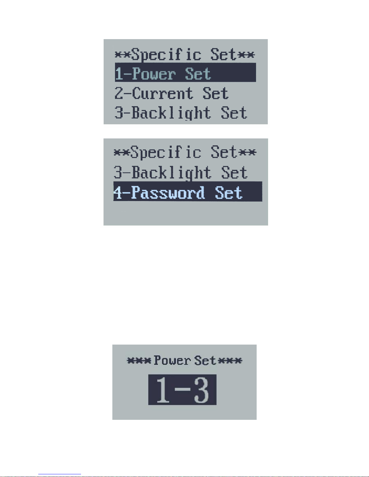
Personalized parameter settings Interface
◆Power Assistant Level Settings
Power Assistant Level option(this function is not suitable for
scooter)
Power Set represents power assistant level settings.In assistance
level settings, there are 8 modes to select: 0-3, 1-3, 0-5, 1-5, 0-7, 1-7, 0-9,
1-9. The default mode is 1-3.
To select the mode of assistance level, press UP/DOWN to increase
or decrease until the desired setting is displayed.To store the changed
setting and access the PAS ratio settings page, press MODE button.
PAS Mode option Interface
10
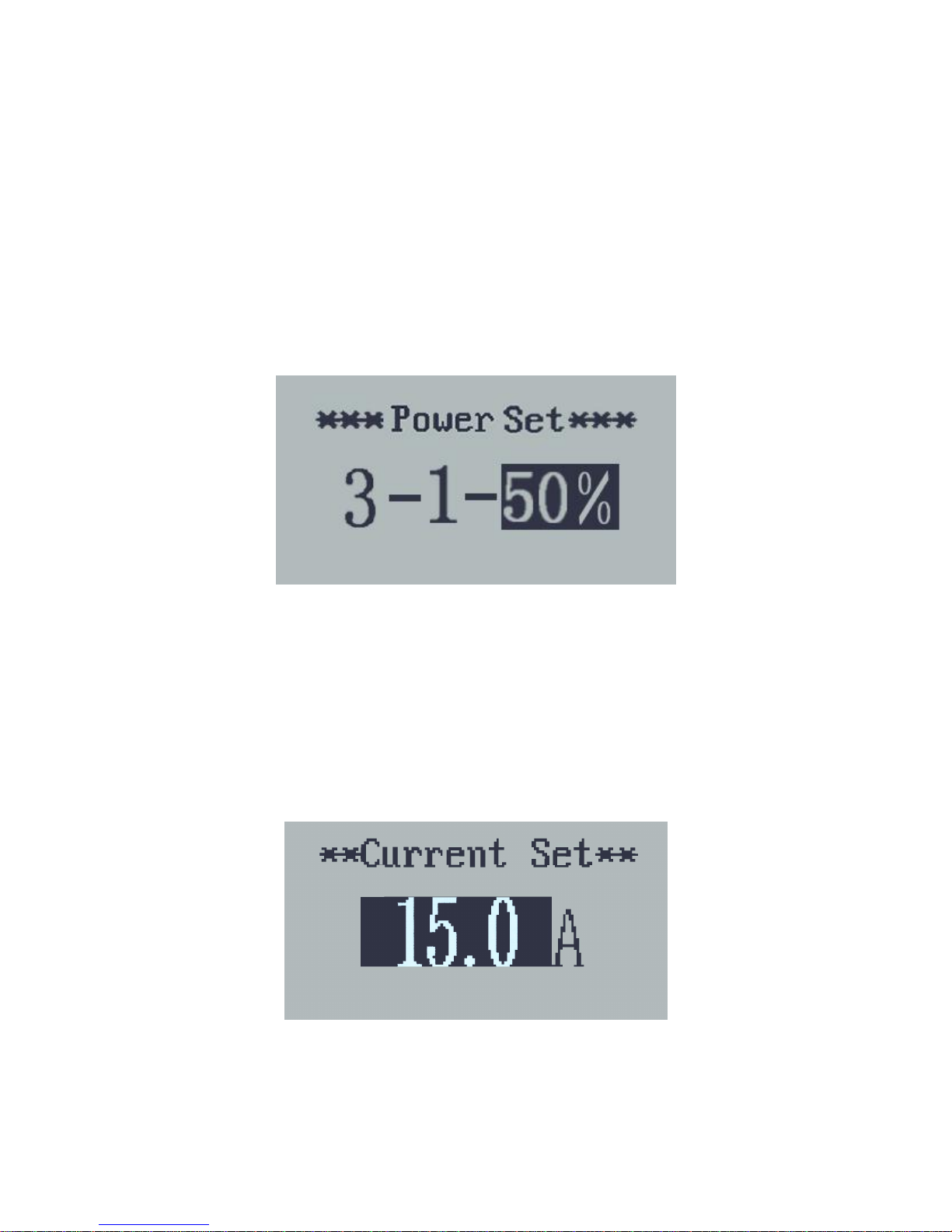
PAS Ratio Settings(this function is not suitable for scooter)
To modify the value of PAS ratio can match the different
requirements. For example, the range is “45-55 percent” of 1 level,
bottom value can be modified and the default is 50 percent.
Press UP or DOWN button to increase or decrease the number.
Press MODE button to confirm and turn to the next PAS ratio settings. 9
levels is the maximum. After all PAS ratio inputted, press MODE button
to confirm and return to personalized parameter settings interface.
Various symbol definitions please refer to Attached list 2.
PAS Ratio Interface
◆Controller Over-Current Cut Settings
Current Set represents controller over-current cut settings. It can
be changed from 7.0A to 25.0A. The default value is 15A.
To change basic settings, press the UP/DOWN button to increase
or decrease the value of the current.To store a changed setting, hold the
MODE button and then return to personalized parameter settings
interface.
Current Set Interface

11
◆Backlight settings
Backlight Set represents backlight settings. Level “1” is the low
brightness. Level “2” is the middle brightness. Level “3” is high brightness.
The default value is “2”.
To modify the backlight brightness, press the UP/DOWN button to
increase or decrease until the desired setting is displayed.To store a
changed setting, press the MODE button and then return to personalized
parameter settings interface.
Backlight Settings Interface
◆Power-on Password Settings
Password Set represents power-on password settings. The default
power-on password is 1212.
To access the power-on password settings, press UP/DOWN to
modify the value and then press MODE to confirm digit one by one until
the correct 4-digit password is completed, and then press MODE to
access power-on password enable settings interface, otherwise stay on
the password input state.
Power-on Password Entering Interface
Power-on Password Enable/Disable
Press MODE button to enter power-on password enable/disable

12
interface. Press UP or DOWN button to select Disable or Enable and
press MODE button to confirm. Power-on Password default is Enable. If
you choose Enable, press MODE button to enter Power-on Password
Modify interface, otherwise exit the power-on password settings
interface.
Power-on Password Disable/Enable Interface
Power-on Password Modify
When the display shows “Password Set, P3”, press UP/DOWN to
modify the value and then press MODE to confirm digit one by one until
the new 4-digit password is completed.
To store the new power-on password, hold MODE button for 2 s
and then exit settings.
When switching the eBike system on next time, the display will
show P1,0000, please input the new password to power on.
Power-on Password Modify Interface
◆Exit settings
In the settings state, press MODE button to confirm the input. Hold
MODE button more than 2 seconds to save the settings and then exit the
current settings. Hold DOWN button more than 2 seconds to cancel the
operating but not saving the settings data, and then exit the settings state.
■If there is not any operations in one minute, display will exit the
settings state automatically.

13
Factory Reset
Factory Reset represents recover default settings. Press both UP
and MODE button more than 2 seconds to enter recover default settings.
Press UP or DOWN button to choose Y or N. Y means that recovers
default settings. N means that do not recover default settings. When it is
Y, hold MODE button more than 2 seconds to recover default
settings,then display "OK" represents operation complete and return to
general display state. The default state is N.
Recover Default Settings Interface
Quality Assurance and Warranty Scope
ⅠWarranty
1) The warranty will be valid only for products used in normal usage
and conditions.
2) The warranty is valid for 24 months after the shipment or delivery
to the customer.
ⅡThe following items do not belong to our warranty scope:
1)Shell is broken when display is out of the factory.
2)Wire is broken.
3)It cannot be demolished.
4)Wire of the display is broken.
5)The fault or damage is caused by the force majure (such as fire,
earthquake, etc,) or natural disasters like lighting, etc.
6)Beyond the warranty time.

14
Connection layout
Connector line sequence
Display-side adapter Switch wiring
Line sequence table
Line sequence
Color
Function
1
Red
VCC
2
Blue
K
3
Yellow
TX
4
Green
RX
5
White
GND
6
Black
GND
7
Gray
SP
8
Purple
SV
■Some wire use the water-proof connector, users can not see the
inside color.
Operation Cautions
◆Be careful of safe use. Don’t attempt to release the connector
when battery is on power.
◆Try to avoid hitting.
◆Don’t modify system parameters to avoid parameters disorder.
◆Make the display repaired when error code appears.

15
Attached list 1:Error code definition
Attached list 2:Power assist table
Error Code
Definition
21
Current Abnormality
22
Throttle Abnormality
23
Motor Abnormality
24
Motor Hall Signal Abnormality
25
Brake Abnormality
30
Communication Abnormality
Table of contents
Other Tianjin Key-Disp Bicycle Accessories manuals


