Tiltamax Nucleus-M WLC-T03 User manual

A R M YO U R C A M E RA
W W W.
T I LTA.COM
USER GUIDE
Nucleus-M Wireless Follow Focus System
39T
0.8M
TILTA TECHNOLOGY CO., LTD
TEL:+86-0755-33185005
Fax:+86-0755-33185003
Add: 2nd Floor, Building B, Qiaode High Technology Park,
Road No.7, Guangming New Dist, Shenzhen, 518125
TEL: +1 (818) 561-4991
Address: 2801 W Magnolia Blvd. Burbank, California, 91505
TILTA INC. (UNITED STATES)
WLC-T03
NO.:WLCT030180508EN03

X4
X2X2
X2
X2
X2
39T
0.8M
Optional Accessories For More Information Please Visit: www.tilta.com
Quick Release
Handgrip Bridge
Wireless Motor
Run/Stop Cable
Follow Focus
Marking Disk
Motor Antenna
Left Handle Thumb Joystick Unit
Nucleus-N Motor
Universal Gimbal Ring Adaptor w/ Rosette
Battery Charger
18650 Battery Flight Case
740mm P-TAP Power Cable
740mm 2pin Lemo Cable 740mm
3Pin Fischer Cable
Straight 296mm Motor Cable
Straight 180mm Motor Cable
Standard Packing List
Battery Charger
FIZ Unit Lanyard Motor Antenna
FIZ Wireless Hand Unit Left Wireless Handle
Straight 296mm
Motor Cable
Right Wireless Handle Wireless Motor
Straight 180mm
Motor Cable
740mm P-TAP
Power Cable
Follow Focus
Marking Disk
Handle to Arri Standard
Rosette Adaptor
Handle to Gimbal
Bar Adaptor
(25mm/30mm diameter)
Waterproof
Safety Case
Follow Focus Ring
0.4/0.5/0.6 Gear Follow Focus Ring x2 Long Distance Wireless Module
02
Product Overview:
The Tiltamax Nucleus-M Wireless Follow Focus System:
Made for industry professionals
Quick, Easy, and Reliable precision control of Focus, Iris, and Zoom
Compatible with Cine Lenses and Photo Lenses
Ambidextrous FIZ Unit design
Ergonomic Handle grips
Low Noise High Torque Motors
Compact and Modular
Multi-Channel System
1. Please read this disclaimer before use
2. User is responsible for operation and consequences of operation
3. Tilta is not responsible for any modication made by the user to software or hardware
which may cause immediate or prolonged immeasurable damage to the unit
4. For additional troubleshooting please call us at:
International: +86 4006 1998 67
North America: +1 818 561 4991
Disclaimer:
01

Motor
Component Functions
04
Reciever:
02. ENTER Button
06. 0.8 Gear
Indicates Status of Motor
Compatible via 15mm Bushing
01. POWER Button
Turn on/off
03. MENU Button
Enter Main Menu
Conrm Selection
04.UP Button and CHANNEL +
Upward Selection and Increase Channel Number
05.DOWN Button and CHANNEL -
Downward Selection and Decrease Channel Number
Connects to Lens Gear to
Adjust Focus, Iris, or Zoom
Power and Communication In/Out
Power and Communication In/Out
09.Wireless Antenna
Receives Wireless Signal
For Data Transfer and Updating Firmware
11. Indicator Light
12.15/19mm Rod Adapter
10. Micro USB Port
07. EXT-2 Port
08. EXT-1 Port
Top Bottom
WLC-T03M
5
1
2
3
4
6
9
12
11
7
810
FIZ Hand Unit
Transmitter:
02. REC Button
03. FUNCTION Button
04. DELETE Button
05. MARKER Button
06. CALIBRATE Button
07. MENU Button
10. ENTER Button
11. USB port
14. 18650 Battery Compartment Latch
15.
01. ZOOM Joystick
For Data Transfer and Updating Firmware
12. EXT port
13. IRIS Wheel
Iris Controller and Controls Zoom Speed
Battery Compartment Button
Push to open Battery Compartment latch
16. Light Sensor
Adjusts Key LED and Screen Brightness
17. POWER Button
18. Lanyard Attachment
19. FOCUS Knob
Focus Controller
20.Attachment Bracket
Activate Run/Stop
Make Marks
Enter Main Menu
08. UP Button
Upward Selection
09. DOWN Button
Downward Selection
Hold to Calibrate Range of Lens
Zoom Controller
Power and Communication In/Out
Component Functions
03
BottomTop
186 50
1
2
3
4
5
6
7
89
10
17
18
19
11
12
13
14
16
20
15

Controller :
04. MENU Button
01. RECORD Button
Activate Run/Stop
02. FOCUS / IRIS Knob
03. Knob Degree Adjustment Switch
3 Rotation Settings: 85, 180, 310Degrees
Enter Main Menu
05. LCD Display
06. EXT Port
Power and Communication In/Out
ZOOM Distance can be control
Push to open Battery Compartment Latch
07.ZOOM Joystick
08. Battery Compartment Button
09. 18650 Battery Compartment Latch
1 0.Knob A-B Marker Button
11.Joystick A-B Marker Button
Creating Close Focus and Innity Focus Marks
Creating Close Focus and Innity Focus Marks
Joystick LED Indicator
Knob LED Indicator
12.Z LED
13.F LED
Component Functions
Right Wireless Handle
06
6
ZF
2
3
18650
9
7
11
10
8
12
13
4
5
1
Component Functions
Controller:
04. MENU Button
01. RECORD Button
Activate Run/Stop
02. FOCUS / IRIS Knob
03. Knob Degree Adjustment Switch
Rotation Settings: 85, 180, 310 Degrees
Enter Main Menu
05. LCD Display
06. EXT Port
Power and Communication In/Out
Push to open Battery Compartment Latch
Joystick LED Indicator
07.Battery Compartment Button
08.18650 Battery Compartment Latch
09. A-B Marker Button
Creating Close Focus and Innity Focus Marks
10.Z LED
11.F LED
Optional: Left Handle Thumb Joystick Unit
Knob LED Indicator
Left Wireless Handle
05
WLC- T03 TL
Z
F
6
10
11
1
9
4
5
7
2
3
18650
8

1
2
3
4
19mm Rod
Compatibility
15mm Rod
Compatibility
Slide the Motor into position under the lens gear.
Bushing allows for 19mm to 15mm compatibility
1. Loosen knob on Rod Adapter
2. Adjust the position of the Motor
3. Embrace the Motor Gear with the Lens
Gear snuggly
4. Tighten the knob on Rod
Adaptor
08
Nucleus-M: Shoulder Mount Assembly
Inserting the Batteries
Attaching the Motor to a DSLR Camera
Note: If the lens already has a 0.8 gear or has been modied to have one, then the motor
can be attached and calibration can begin just as if it were a cine lens
Add the follow focus ring to the lens. Secure it tightly. Make sure the fastener is not
in a position where the motor's gear will hit it during it's calibration run.
Once the follow focus ring is on the lens, follow the same steps for calibration as if
it were a cine lens
07
Hold the Handle. Push the【Open】.
The battery compartment latch will release.
Place (2) 18650 Batteries in any direction -
as long as positive and negative ends on
the batteries touch - and then close the latch
Installing the Batteries in the FIZ
Hold the FIZ Unit. Push the【Open】.
The battery compartment latch will release.
Place (2) 18650 Batteries in any direction
and then close the latch
Installing the Batteries in the Handles
+
-
+-

4
1. Attach the Handgrip Bridge to the Rods
2. Lock down the bridge connection via
tightening screw disk
Nucleus-M: Shoulder Mount Assembly
5
The Handle to Arri Standard Rosette Adaptor connects to
the Quick Release Handgrip Bridge and any other
accessory with Arri Standard Rosettes
1. Use Allen Key to screw down the Arri
Standard Rosette Adaptor into the Handle
2. Attach Arri Standard Rosette from Handle to
the Quick Release Handgrip Bridge and secure
connection via large thumb screw
10
19mm or 15mm Rods
15mm Rods
P-tap
POWER
Each Motor has (1) EXT-1 port and (1) EXT-2 port
Both ports can Power In/Out as well as control Run/Stop
1. Power can be sent directly to the Motor and/or daisy-chained from Motor to Motor
2. A single cable can be used to power the motor and activate the camera's R/S, if the camera
port is capable of power out and R/S - such as the 3-pin LEMO ports on the Tilta Alexa Mini and
RED DSMC2 Cages
For Example:
ARRI XT-RS port
TILTA FOR ALEXA MINI Cage -14.8v 3pin R/S port
TILTA FOR RED DSMC2 Cage -14.8v 3pin R/S port
Motor:
Power Supply
and Run/Stop
If Camera Port is not capable of both R/S and
Power out, then separate cables must be used
to achieve motor power supply and R/S
(see image below)
1. Connect Motor to Motor via motor
connection cable through its EXT-1 to
the other motor's EXT-2 port
2. Use the P-TAP cable to provide power
from the battery to a motor through its
EXT-1 port
* Use either the straight 296mm cable orthe straight
180mm cable to connect the motors according to
your needs
If the motors are already connected to the camera through
a R/S with Power Output port (as seen in Fig 1) an additional
power cable will cause the motors to shut down
Warning:
09
cam e ra
ca me ra
POWER+R/SPOWER
R/S

1
2
3.1
Handle to Gimbal Bar Assembly
1. Use Allen Key to screw down
the Gimbal Bar Adaptor into
the Handle
2. Attach Gimbal Bar Adaptor
from Handle to the Gravity
Gimbal Bar and secure
connection via thumb screw
The Universal Gimbal Adaptor is optional.
Bushings are also available for FreeFly and DJI Gimbals
12
3.2
1. Use Allen Key to screw down the Arri Standard Rosette Adaptor into
the Handle. Attach Arri Standard Rosette from Handle to the Universal
Gimbal Adaptor with Rosette and secure connection via large thumb
screw
2. Attach Universal Gimbal Adaptor to Gimbal Ring. Repeat for
opposite side
Handle to Universal Gimbal Adaptor with Rosette Assembly
1
2
Nucleus-M: Gravity Gimbal and Drone Assembly
1
1. Slide the Motors into position
under the lens gear. When using
the Nucleus-M on a gimbal or
drone it is recommend to place
one motor on each side to
maintain the camera's equilibrium
2. Utilizing the quick release from the
gimbal, easily mount a balanced
camera with the Nucleus-M to a
Drone, Handle Bars, or Jib Arm
2
11
Original chips manufactured in
America allow for a wireless range
boost of up to 2000 meters
Long Distance Wireless Module
(Sold Separately)

Hold【POWER】to Open Main Menu
2. Motor
Turn-off 1.1 Hold【POWER】then release, choose the mode
Double click【POWER】to conrm
1.2 Hold 【POWER】Down for 3 Seconds and then the designated unit
will shutdown
3. Handle
Turn-on to Open Main Menu
Turn-off Hold Down for 3 Seconds and then the designated unit will shutdown
Shutdown this motor only
Shutdown all the motors
Turn-on
Hold
14
AF-ER
POS+000 50%
MOT:000
CUR:0.0
RI00
NO.2
RAG:00 00m 00 00
00: 03: 22
V:00.0
01L
STBY
NO
Power Off All
Power Off This
Power Key Off
Up Keys Select
Other Keys Cancel
V7.8 STBY FREE
+000
FREE
-000
S:30 R
01 1
KL
LJ2
Power Off
in 3S
1. FIZ Hand Unit
Hold【POWER】to Open the Main Menu
Turn-Off 1.1 Hold【POWER】then release. Use to toggle between selections.
Double Click【POWER】to conrm
1.2 Hold【POWER】Down for 3 Seconds and then the designated unit
will shutdown
Turn-On
Turn On / Turn Off
How to Use: Nucleus-M
13
STBY Slave
F 0
A
Z+000
50% 3
V:5.9
50%
00
+
L
STBY Slave
F 0
A
I+000 50% 2
Z+000 50% 3
V:5.9
S:30 Unlock
50%
00
+
L
STBY Slave
F 0
A
Z+000
50% 3
V:5.9
50%
00
+
L
STBY Slave
F 0
A
I+000 50% 2
Z+000 50% 3
V:5.9
S:30 Unlock
50%
00
+
L
Only shutdown FIZ Unit
Shutdown all
connected devices
Off this
Off All
In 3S Cancel

1
3
2
2. Assigning the Motor Numbers to the FIZ Unit
1. Press【MENU】to enter the
Main Menu
2. Use to highlight
"MOTOR" - press【ENTER】
to conrm
3. Choose the corresponding
controller of the FIZ Unit to the
designated function of each Motor.
For Example, pair the Motor on the
Focus gear of the Lens to the Focus
Knob on the FIZ. In this case, that
Motor has been assigned as Motor
Number 1.
Highlight "FOCUS" and press【ENTER】
4. Use to highlight "SYNC" -
press【ENTER】to conrm
5. Use to highlight "Motor 1" -
press【ENTER】to conrm.
Conrmation is identied by a
check mark. If a Motor Number has
no check mark, it is not synced
with a controller on the FIZ
6. Repeat Steps 1 - 5, to assign the
Zoom and Iris Motor to the FIZ Unit.
Press【MENU】to return to the
Home Screen. If the display looks like
the picture above, then all 3 Motors
have been synced properly
Note: Motors cannot share the same Motor Number. A Motor can identify if its Motor
Number is being repeated and will automatically cancel the last Motor Number assigned
MOTOR 1 MOTOR 2 MOTOR 3
(FOCUS) (ZOOM) (IRIS Sold Separately)
FIZ Unit - FOCUS Knob
FIZ Unit - IRIS Wheel
FIZ Unit - ZOOM Joystick
Below is a Figure for conceptual demonstration purposes depicting a default assignment
of the FIZ Unit and 3Motors. Use the example below for quick start and troubleshooting
16
Wireless
Motor
Function
Torque
SYNC
Direction
Back Enter
Motor 1
STBY Slave
F0
A
I+000 50%
2
Z+000
50%
3
V:5.9
S:30 Unlock
50%
01
+
M
Focus
ZOOM
IRI
STBY Master
F1
A
I+000 50%
2
Z+000
50%
3
V:5.9
S:30 Unlock
50%
01
+
M
Motor 2
Motor 3
Back Set
Back Enter Back Enter
Wireless Signal Range
MOTOR Number (F=Focus)
MOTOR Number (I=Iris)
MOTOR Number (Z=Zoom)
CHANNEL
ENTER Button
UP / DOWN Buttons
POWER Button
MENU Button
1. Setting the FIZ Unit's Channel
1. From the Home Screen,
use【MENU】to open the
Menu System
2. Use to highlight "WIRELESS"-
press【ENTER】to conrm
3.With "2.4G" highlighted,
press【ENTER】to conrm
4. Continue pressing【ENTER】
until "M" is selected. This value
represents the "2.4G" or Long
Range Value:
H MAX: Furthest Wireless Distance,
High Power Consumption
M Medium: Recommended Wireless Distance,
Average Power Consumption
L MIN: Short Wireless Distance,
Low Power Consumption
OFF: No Wireless Signal Transmitted
used when hardwiring FIZ to Motor
5. Highlight CHANNEL by pressing
, then use to change
the Channel Number. Available
Channels range from 00-15. Set
the CHANNEL to "02"
6. Press【MENU】to return to the
Home Screen. If the screen looks
like the image above then the FIZ
Unit's Channel has been set
15
Syncing FIZ Hand Unit with Motors
REC Master
F 0
A
I+000 50%
2
Z+000
50%
3
V:5.9
S:30 Unlock
50%
02
+
M
REC Master
F 0
A
I+000 50%
2
Z+000
50%
3
V:5.9
S:30 Unlock
50%
00
+
LBack Enter
2.4G
Mode: M
Channel 00:
设 置
返 回
Back Enter
Wireless
Motor
Function
设 置
返 回
The FIZ Unit Channel Number must Match one of the daisy-chained Motor Channels.
The FIZ Unit defaults to MASTER mode. To use the Handles, set FIZ Unit to SLAVE mode.
Note:
Mode: M
Channel 02:

AF-ER
POS+000
50%
MOT:000
CUR:0.0
RI00
NO.2
RAG:00
00m 00'00'
00:03 22
V:00.0
01L
STBY
NO
:
'
1. From the Home Scree n ,
double click【MENU】to open the
Menu System
3. Continue pressing【ENTER】until
"M" is selected. This value represents
the "2.4G" or Long Range Value:
5. Switching between the FIZ Unit and Handles for Control of Motors
The FIZ Unit defaults to MASTER mode. To use the Handles, set FIZ Unit to SLAVE mode
Double Click【FUNC】on the FIZ Unit to switch
between Master and Slave Modes
When the display reads "Master" the FIZ Unit has priority
control over the Motors
When the display reads "Slave" the Handles have
priority control over the Motors
For the purposes of this tutorial, let's keep the FIZ in
Master mode
By default the FIZ Unit has priority control over the Motors. To release the FIZ Unit's control
and give the Handles priority control, double click on the FIZ Unit's【FUNC】. If "SLAVE"
appears on the Home Screen display, this is conrmation that the handles now have
priority control over the Motors
Recalibration is not necessary, but be sure to assign a controller and do not attempt to
control one motor with the FIZ and Handle simultaneously
4. Setting the Motor's Motor Number
For the purposes of this tutorial, if the Motor is not assigned to Motor No. 1, it will not be
synced with the FIZ's focus knob controller
1. From the Home Screen,
double click【MENU】to open
the Menu System
2. Use to highlight
"MOTOR NO." - double click
【ENTER】to conrm
4. Press【MENU】to return
to the Home Screen. If the display
looks like the image above then
the Motor Number has been set.
Lastly, repeat the steps above to
match the corresponding Motor
No. 2 and 3 with the FIZ Unit
controller
In this case, set the Motor No. to 1,
corresponding to the Focus on the FIZ
MENU Button
ENTER Button
UP Button
POWER Button
DOWN Button
Motor Number
Channel
Wireless Signal Range
3. Setting the Motor's Channel
H MAX: Furthest Wireless Distance,
High Power Consumption
Recommended Wireless Distance,
Average Power Consumption
L MIN: Short Wireless Distance,
Low Power Consumption
OFF: No Wireless Signal Transmitted
Used when hardwiring FIZ and/or Handle
to Motor(s)
M Medium:
17 18
4. Press to return to 【MENU】
the Home Screen
5. Double click to change the channel.
Set the Channel to "01" then
press MENU to return to the Home Screen. 【 】
If the display looks like the image on the left,
then the Motor Channel has been set
2. Use to highlight
"WIRELESS" - double click
【ENTER】 to conrm
3. Use to assign the Motor
a number between 1 and 4.
Wireless Mode
= M
AF-ER
POS+000
50%
MOT:000
CUR:0.0
RI00
NO.2
RAG:00
00m 00'00'
00:03 22
V:00.0
01
M
STBY
NO
:
'
AF-ER
POS+000
50%
MOT:000
CUR:0.0
RI00
NO.2
RAG:00
00m 00'00'
00:03 22
V:00.0
01L
STBY
NO
:
'
Wireless
Motor No.
Auto CAL Mode
Restore
Information
STBY Master
F 0
A
I+000 50%
2
Z+000
50%
3
V:5.9
S:30 Unlock
50%
00
+
L
Motor No.
= 1
AF-ER
POS+000
50%
MOT:000
CUR:0.0
RI00
NO.2
RAG:00
00m 00'00'
00:03 22
V:00.0
01L
STBY
NO
:
'Wireless
Motor No.
Auto CAL Mode
Restore
Information
AF-ER
POS+000
50%
MOT:000
CUR:0.0
RI00
NO.1
RAG:00
00m 00'00'
00:03 22
V:00.0
01L
STBY
NO
:
'

1. From the Home Screen,
double click【MENU】
to open the Menu System
4. Use to return to the
Home Screen. If the Home
Screen appears like the
image above, then the LORA
has been conrmed
5. Use to select
"CHANNEL" -double click
【MENU】to conrm
Double Click for MENU
Single Click for UP
POWER/REC/RETURN
DOWN Button
Motor No.
Channel
Wireless Signal Range
Syncing Handles with Motors
1. Setting the Handle's Channel
19
2. Use the to select
"WIRELESS" - double click
【MENU】to conrm
3. Use to select "M". This value
represents the "2.4G" or Long Range
Value:
H MAX: Furthest Wireless Distance,
High Power Consumption
M Medium : Recommended Wireless
Distance, Average Power
Consumption
L Min: Short Wireless Distance,
Low Power Consumption
OFF: No Wireless Signal Transmitted
For hardwiring to Motor
6. Use to change
the Channel Number.
Available Channels range
from 00-15. Set the
CHANNEL to "02"
7. Use to return to the
Home Screen. If the Home Screen
appears like the image above,
then the Channel has been
conrmed
Wireless Channel
= 02
Wireless Mode
= M
V7.8 STBY FREE
+000
FREE
-000
S:30 R
01 2
J
V7.8 STBY FREE
+000
FREE
-000
S:30 R
01 2
J
M
V7.8 STBY FREE
+000
FREE
-000
S:30 R
022
J
M
Wireless
Knob No.
Knob Dir
Knob Torque
Channel
Wireless
Knob No.
Knob Dir
V7.8 STBY FREE
+000
FREE
-000
S:30 R
01 1
L
KL
J2
1. From the Home Screen,
double click【MENU】to open
the Menu System. Use to
select "KNOB NO." - double
click【MENU】to conrm
2. When a Motor has a been assigned a
Motor No, that number corresponds to the
value that can be selected by the Handle's
Controller. Thus, the Knob Motor Control No.
will sync the the Motor assigned that
number between 1 and 4. Using a value of
"0" prevents any controller connection to a
motor.
In this case, set the Knob Motor Control No.
to 1
3. Use to return to the Home
Screen. If the Home Screen
appears like the image above,
then the Motor has been synced
with the Knob
1. From the Home Screen,
double click【MENU】to the
open the Menu System. Use
to select "JOYSTICK
NO." - double click【MENU】
to conrm
2. When a Motor has a been assigned a
Motor No, that number corresponds to the
value that can be selected by the Handle's
Controller. Thus, the Joystick Motor Control
No. will sync the the Motor assigned that
number between 1 and 4. Using a value of
"0" prevents any controller connection to a
motor
In this case, set the Joystick Motor Control
No. to 2
2. Assigning Handle's Knob to Motor
3. Assigning Handle's Joystick to Motor
20
3. Use to teturn to the Home
Screen. If the Home Screen
appears like the image above,
then the Motor has been synced
with the Joystick
Knob Motor
Control No.
= 1
Knob No.
Knob Dir
Knob Torque
JoyStick No.
JoyStick Motor
Control No.
= 2
V7.8 STBY FREE
+000
FREE
-000
S:30 R
01 2
J
M
V7.8 STBY FREE
+000
FREE
-000
S:30 R
01J2
M
JoyStick No.
JoyStick Dir
JoyStick Tor
JoyStick SPD
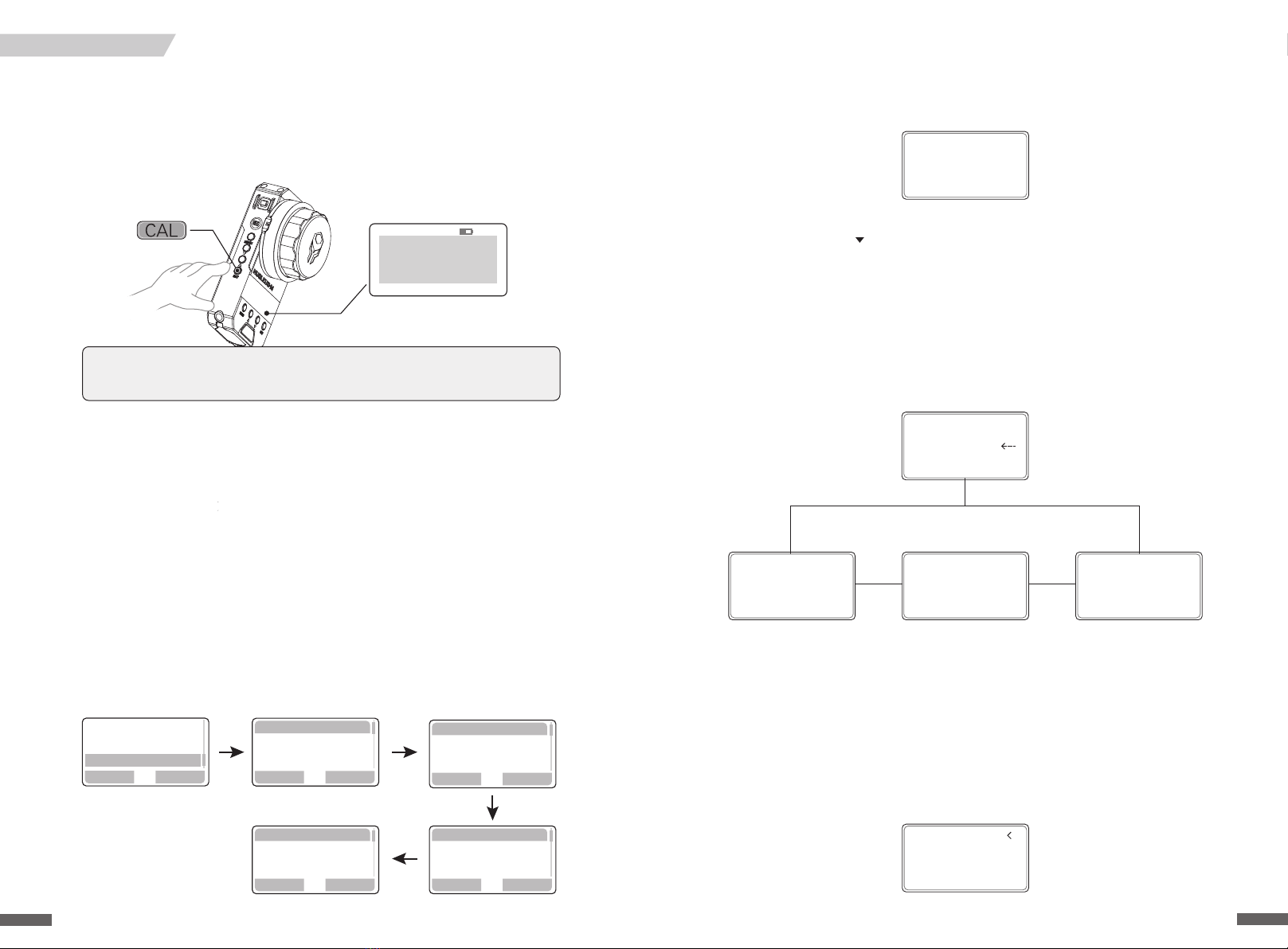
2. Calibrating from the Motor
2.1 Setting the Auto CAL Mode
2.2 Single and Multi-Motor Calibration from the Motor
When the Motor is powered on, the following screen may appear.
This screen is dependent on the "Auto CAL Mode." This auto calibration setting can be found
in the Motor's menu. Use to select "Auto CAL Mode" - toggle between the 3 options
pictured below
The "Manual Start" setting will prevent the Motor from calibrating when initially turned on
The "Auto Start After 3 Secs" setting will automatically trigger calibration after 3 seconds when
initially turned on. The user has 3 seconds to press any button on the motor to cancel the
calibration
The "Auto Start Immediately setting will immediately trigger calibration from the Motor the "
moment it turns on
Once a calibration mode has been selected the Motor will turn red and calibration will begin.
When the Motor's LED turns white, calibration has nished
Calibration from the Motor can happen at anytime, simply hold down【CAL】and release.
Two options will appear: "CALIBRATE THIS" and "CALIBRATE ALL". "CALIBRATE THIS" will begin
calibration on only the motor being programmed. "CALIBRATE ALL" will begin calibration on
all motor's daisy-chained to it. Double click【CAL】to conrm and the motor(s) will begin
calibration
22
Calibrate This
Calibrate All
Cal Key Run
Up Key select
Other Keys Cancel
Start calibrate
In 3S
Any Key Cancle
Motor Calibrate
Power On
=Auto start
After 3S
Motor Calibrate
Power On
=Auto start
Immediately
Motor Calibrate
Power On
=Manual Start
Wireless
Motor No.
Auto CAL Mode
Restore
Information
1.2 Calibration of Lens without Hard Stops
When using cine lenses or modied photo-lenses with follow focus gears and hard
stops, calibrate from the FIZ unit by holding down【CAL】. The screen will show a
3 second countdown. Holding down【CAL】on the motor will also trigger a calibration
Lenses without hard stops need to be manually calibrated. Follow the images below to set
manual calibration from the FIZ. For this example, we will calibrate【Focus】
1) Be sure that the Motor is not making contact with the lens gear
2) Turn the FIZ knob so that it is in the middle of its range
3) Now, manually position the lens gear to "middle" focus position between close and innity
4) Securely attach the Motor to the lenses focus gear
5) Take the FIZ Unit and press the MENU Button to open the menu system
6) Highlight and select "FUNCTION"
7) Select "MANUAL CAL". Three options will appear: FOCUS, ZOOM, IRIS
8)Choose the one in need of calibration according to your needs- in this case select Focus
9)Follow the directions on the screen. Turn the knob completely counterclockwise and select
enter. This sets the close focus
10) Now follow the directions on the screen once more. Turn the knob completely clockwise,
the Motor should pull the lens gear to innity. Select OK and return to the Main Menu. The
Focus should now be properly calibrated
1.Calibration from the FIZ Unit
1.1 Calibration of Lens with Hard Stops
CALIBRATION
21
Note:By default the Motors are set to the "Manual Start" - Auto CAL Mode. Motors need
to be set the "Auto Start" Mode and calibrate on a lens before the CAL Button can be used
on the FIZ and Handles. Doing so in this order will prevent any damage to the lens
STBY Slave H12
A:
A
I:+9424 50% F:+2220 3
Z:+0000 50% S:15
U:3.5U
50%
CAL ALL
CAL MOT 1
In 3Secends
Back Enter
Wireless
Motor
Function
Back Enter
Manual Cal
Calibrate Knob
Key LED
Back Enter
Focus
ZOOM
IRIS
Back OK
Turn the Knob
until Focus/Z/I
reaches maximum
Back
Turn Focus/Z/I
until minimum
Lock the motors
Enter

2.Creating and Deleting Hard Stops from the Handle
Hard stops can be set on the Handles' Knob. Rotate the Knob and double click on the front
【AB】to set【A】Mark. The mark has been conrmed when the "F" LED blinks green. Rotate
the Knob to the next mark and double click【AB】to set a【B】Mark. The "F" LED will glow
solid green. Now the full 310 degree throw of the Knob controller will reect【A】 to【B】Mark.
To delete the hard stops, double click on【AB】again. The "F" LED will turn off
2.1 Creating Hard Stops/ Limits via Knob controller
2.2 Hard Stops / Limits via Thumb Unit / Joystick controller
Hard stops can be set on the Handles' Joystick. Position the joystick and double click on the
thumb unit's【AB】to set【A】Mark. The mark has been conrmed when the "Z" LED blinks
red. Position the joystick to the next mark and double click【AB】to set a【B】Mark. The "Z"
LED will glow solid red. Now the full throw of the Joystick controller will reect the【A】to【B】
Mark. To delete the hard stops, double click on【AB】again. The "F" LED will turn off. On the
Joystick, the speed from which【A】 to【B】 Marks are reached is determined by the Speed
controller, when Iris has been assigned to "0"
24
V7.8 STBY A--B
+000
FREE
-000
S:30 R
01 1
KL
L2
J
V7.8 STBY
A--B
+000
FREE
-000
S:30 R
01 1
KL
L2
J
ZOOM
A-B
ZF
Setting the Range & Hard Stops on Handles
1. Setting the Rotation Degree on the Knob
Some lenses have long focus throws. To compensate for this, the Handle's knob can be set to
various rotational degrees. Both the left and right handles can change their rotational degrees.
Shortening the knob's rotational degrees will shorten long focus throws by making the motor
speed up and vice-versa; long knob degrees can be used on short focus throws.There are 3
ranges that can be chosen. The following directions pertain to the Right Handle. When using
the Left Handle inverse the spin direction
Pull【RANGE】 . The letter "L" will appear on the Handle's display. "L" or ""Long" sets the knob
to the longest distance it can rotate from left to right, 310 degrees. The motor will move slowly
in this setting
Pull【RANGE】 . The letter "L" will appear on the Handle's display. Spin the Knob clockwise
completely till the knob stops. Push【RANGE】 . The letter "S" will appear on the Handle's
display. " S " or " Short " sets the knob to the shortest rotational distance , 85 degrees
Pull【RANGE】 . The letter "L" will appear on the Handle's display. Spin the Knob counter
clockwise completely till the knob stops. Push【RANGE】 .The letter "M" will appear on the
Handle's display. "M" or "Medium" sets the knob to 180 degrees
23
V7.8 STBY FREE
+999
FREE
-000
S:30 R
04K
2
J
1
L
H
V7.8 STBY FREE
+866
FREE
-000
S:30 R
04K
2
J
1
S
H
V7.8 STBY FREE
+456
FREE
-000
S:30 R
04K
2
J
1
M
H
310°
180 °
85°

6. Syncing the Motor
Click on【MENU】enter the menu system. Use to highlight " Motor " and 【ENTER】.
Highlight " Focus ",【ENTER】. Highlight " SYNC" 【,ENTER】. Three options will appear: Motor 1,
Motor 2, Motor 3 - highlight and select the desired Motor. Click enter and a conrmation will
appear as a check mark. Press【MENU】till the Home Screen appears
5. Changing the Torque of Motors
Click on the【MENU】to enter the menu system. Use to highlight " Motor " and【ENTE-
R】. Highlight " Focus ", 【ENTER】. Highlight " Torque ", 【ENTER】. Three options will appear:
High,Medium, and Low - highlight and select the desired Torque value. Click enter and a
conrmation will appear as a check mark. Press the【MENU】till the Home Screen appears
7. Setting Hard Stops / Limits
Hard Stops/ Limits can be made on the FIZ unit. Position the Knob to the desired【A】Mark.
Hold down【MARK】. With the【MARK】held down, rotate the Knob to the desired【B】Mark.
Release【MARK】when nished. Conrmation is dened by a vibration. The limited range
selected will expand to the entire throw of the Knob. Below the limited range is identied
by the white bar. Hold the【DEL】 to delete the Hard Stops /Limits
26
Back
Focus
ZOOM
IRIS
Enter
Back Enter
System
Motor
Wireless
Back SET
High
Medium
Low
Back Enter
Torque
SYNC
Direction
STBY Slave
F: 0
I:+000
50%
2
Z:+000
50%
3
V:5.9
S:30 Unlock
50%
00
+
L
Back
Focus
ZOOM
IRIS
Enter
Back Enter
Torque
SYNC
Direction
Back Enter
System
Motor
Wireless
Back
Motor 1
Motor 2
Motor 3
SET
2. Change the Language
3. 2.4G and CHANNEL
Click on【MENU】to enter the menu system. Use to highlight "System". Highlight
"Language" and choose the language as needed by clicking【ENTER】. A conrmation will
appear as a check mark. Push【MENU】repeatedly to return to the Home Screen
4. Run/Stop
Properly attach the R/S cable to the camera. Click on the left side of the FIZ Unit. On
the display, "STBY" will turn into . A vibration will notify the AC that recording has begun
1. Home Screen
Controller Priority Indicator
Recording Status
Battery Voltage
Wireless Signal Range
AB Mark
Motor No.
Motor No.
Motor No.
Focus
Iris Info
Zoom Info Lock / Unlock Indicator
Zoom Speed
Menu and Function
FIZ Hand Unit
Click on【MENU】to enter the menu system. Use to highlight "Wireless". Highlight "2.4G".
Pressing【ENTER】will change the 2.4G Setting. Use to change the Channel; Use to
change the the High, Medium, and Low Torque value
25
Back Enter
System
Motor
Wireless
Enter
Update
Information
Language
Back OK
Back
简体中 文
ENGLISH
Back Enter
Wireless
Function
Motor
Back Enter
2.4G
Enter
Back
MODE : OFF
Channel:12
Back SET
MODE : M
Channel:00
STBY Master
F 0
A
I+000 50%
2
Z+000
50%
3
V:5.9
S:30 Unlock
50%
00
+
L
REC Master
F 0
A
I+000 50%
2
Z+000
50%
3
V:5.9
S:30 Unlock
50%
00
+
L
REC Master
F 0
A
I+000 50%
2
Z+000
50%
3
V:5.9
S:30 Unlock
50%
00
+
L
Battery Indicator

1. Home Screen
Current
Motor
10. Calibrate FIZ Knob
Click the【MENU】, highlight " FUNCTION ", and click【ENTER】. Highlight " Calibrate
Knob" and 【ENTER】. Follow the on screen directions. Rotate the Knob clockwise to
the end for "Minimal", then conrm with【ENTER】. Repeat the process until FIZ Knob
calibrates
4. Changing Motor Number
2. Setting 2.4G
3. Changing Channel
Double click the【CH-】to decrease the Channel number or double click the【CH+】to
increase the Channel number
Double click the【MENU】, select "Wireless", 【ENTER】Button, and use the to pick
between the 2.4G settings
Double click the 【MENU】, select "Motor No.", 【ENTER】, and use the to assign a
Motor Number
28
Wireless Mode
= M
Wireless
Motor No.
Auto CAL Mode
Restore
Information
AF-ER
POS+000 50%
MOT:000
CUR:0.0
RI00
NO.2
RAG:00
00m 00 00
V:14.0
01L
STBY
NO
00:03: 22
AF-ER
POS+000 50%
MOT:000
CUR:0.0
RI00
NO.2
RAG:00
00m 00 00
V:14.0
02L
STBY
NO
00:03: 22
Motor Mode
= 3
Wireless
Motor No.
Auto CAL Mode
Restore
Information
Back Enter
Turn The Knob
until Fucus
reaches Minimal
Are you sure
confirm knob
calibration?
Back
Turn The Knob
until Fucus
reaches Minimal
O K
Back Enter
Wireless
Motor
Function
Back Enter
Manual Cal
Calibrate Knob
Key Led
Power of Signal
Motor Number
Position/Degree of Motor
Damp of Motor
Data Origin
Voltage
Range (Metric)
Range (Standard)
Wireless Signal Range (2.4G)
Elapsed Working Duration
Auto Focus Status
AF-ER
POS+000
50%
MOT:000
CUR:0.0
RI00
No.2
RAG:00
00m
00
00
00: 03:22
V:14.0
01L
STBY
NO
9. Adjusting the Zoom with the Speed Controller Setting
Set the Iris to "0" by having no Motor No. synced to the Iris controller on the FIZ. T h e Home
Screen will now show an "S" where "I" used to be. "S" refers to speed. Now t h e speed of the
Zoom controller can be changed by spinning the Iris wheel controller on the FIZ
If the Iris is set to a Motor No. of 1-4, speed can be controlled by double clicking . The
speed range will increase or decrease by increments of 1 with a range from 1-99, where 99 is
the fastest and 1 is the slowest setting
Press the【MENU】, highlight "System", 【ENTER】, highlight "Factory Reset", and【ENTER】
8. Factory Reset
To perform a snap zoom or “ZIP”,hold down while using the Zoom Joystick Zoom,
hold while using the Zoom Joystick,dividing the current speed value by 10
When does the FIZ Knob need calibration?
1) If the FIZ Knob has been rotated to end and this icon: does not reach the end of the display bar
2) If the motor spins one way then rapidly spins the other way in the same instance
2
The FIZ unit can create up to 10 "soft" marks. Rotate the Focus Knob to the desired mark.
Double click the【MARK】on the side of the FIZ Unit to set a mark. The mark will appear
as a letter. Rotate the Focus Knob to the next desired position and then double click the
【MARK】to create another marker. Vibrations will occur when marks are passed along
the Focus pull. Double clicking the【DEL】will erase markers in reverse alphabetical order
Setting and Deleting Marks
27
Back
System
Wireless
Motor
Enter Back Enter
Fcatory Reset
Update
Information
Back OK
Restore default
settings?
STBY Slave
F: 0
A
I:+000
50%
2
Z:+000
50%
3
V:5.9
S:30 Unlock
50%
00
+
L
STBY Slave
F: 0
A
I:+000
50%
2
Z:+000
50%
3
V:5.9
S:30 Unlock
50%
00
+
L
B C

Double click【MENU】,and use the to select "Knob torque" 30%,50%,90% different
Knob Motor Torquescan beselected
5. Knob Torque
Double click【MENU】 , select " Knob No. " , double click MENU Button to enter , and use
to select Motor Number. Setting Knob No. to "0" prevents a signal transmission
6. Knob Motor Control Number
Double click【MENU】 , select "Knob Dir. " , double click【MENU】to enter , and use to
select Knob Motor Direction. " CW " is " Clockwise. " " CCW " is " Counter Clockwise "
Double click【MENU】, select "Joystick No. " , double click【MENU】to enter , and use to
select Joystick Motor Control No. - setting Joystick No. to " 0 " prevents a signal transmission
7. Knob Motor Direction
8. Joystick
Double click【MENU】, select " Joystick Dir. " , double click【MENU】to enter , and use to
select Joystick Motor Direction. " CW " is " Clockwise. " " CCW " is " Counter-Clockwise "
Double click【MENU】, select " Joystick Tor. " , double click【MENU】to enter , and use to
select Joystick Motor Torque: 30%, 50%, or 90%
30
Knob Motor
Torque
=50%
Knob Torque
JoyStick No.
JoyStick Dir
JoyStick Tor
Knob Motor
Control No.
= 0
Knob No.
Knob Dir
Knob Torque
JoyStick No.
JoyStick Motor
Control No.
= 1
JoyStick No.
JoyStick Dir
JoyStick Tor
JoyStick SPD
Knob Motor
Direction
= CW
Knob Dir
Knob Torque
JoyStick No.
JoyStick Dir
Knob Motor
Direction
= CCW
JoyStick Dir
JoyStick Tor
JoyStick SPD
Calibrate Kb
JoyStick Motor
Direction
= CCW
JoyStick Motor
Direction
= CW
JoyStick Tor
JoyStick SPD
Calibrate Kb
Restore
JoyStick Motor
Torque
= 90%
5. Motor Information
Double click MENU, select "INFORMATION" to check Motor Information
Double click【MENU】, select "RESTORE", 【ENTER】, double click to conrm
6.F actory Reset
Handles
3. Changing the Channel
Double click【MENU】select " Channel " ,【ENTER】and select Channel Number with the , Press
to return to the Home Screen
Double click【MENU】select " Wireless ",【ENTER】and select 2.4G with . Press to return to
the Home Screen
2. Setting the 2.4G
1. Home Screen
Voltage
Wireless Signal
Range (2.4G)
Knob Data
Joystick Data
Recording Status A-B Mark
Motor No.
Range Switch Data
Zoom Angle
T/R (signal)
Zoom Speed
4. Run / Stop
Properly attach a Run/Stop cable. Click on the top of the Handle. If "STBY" on the display
changes to , the recording has commenced
Serial No.
Number of Activations Version (Firmware)
Operational Duration (Mins)
29
Wireless Mode
= M
Wireless
Knob No.
Knob Dir
Knob Torque
Wireless
Motor No.
Auto CAL Mode
Restore
Information
V7.8 REC FREE
+000
FREE
-000
S:30 R
01 1
KL
L2
J
V7.8 STBY FREE
+000
FREE
-000
S:30 R
01 1
KL
L2
J
Wireless Channel
= 12
Channel
Wireless
Knob No.
Knob Dir
Restore default?
Double Click
Down Button
NUCLEUS-M
TILTA Co.Ltd
S:M0000000000
V:17.09.16
F:00000042
T:00000200
V7.8 STBY FREE
+000
FREE
-000
S:30 R
01 2
J
L
1
K
Focus角度
L

Firmware Update
Use the 7-pin to 7-pin LEMO cable to connect the FIZ to a Handle and on the FIZ, repeat
the following steps to update the Handle. Repeat this process for the other handle
Firmware updates are rst downloaded to the FIZ Unit by connecting it to a Mac or PC via
MircoUSB cable. The FIZ unit will appear on the computer as an external drive called, "Tilta."
Drag the les into the FIZ and unplug. Now follow the images below to update the FIZ Unit
itself
FIZ Unit
Handles
Motors
Use the 7-pin to 7-pin LEMO cable to connect the FIZ to a Motor and on the FIZ, repeat
the following steps to update the Motor. Repeat this process for the other motors
For more information on the: Nucleus-M Wireless Follow Focus System
Visit the product page on our website: www.tilta.com
32
You are able to control the motors and their specications by TILTA APP
instead of handwheel and handles
This function will be available later through APP
V17.09.16
Update Joystick
Back OK
V17.09.16
V17.10.19
Upgrade Version
Back OK
System
Wireless
Motor
Back Enter
V17.10.26
Back OK
Update To3M
Wireless
Motor
Back Enter
System Update
Information
Language
Back Enter
Wireless
Motor
Back Enter
System Update
Language
Back Enter
Information
Upgrade
Language
Back Enter
Information
11. Calibrate Handle Knob
1 ) If the motor spins one way then rapidly spins the other way in the same instance
2 ) If the Knob is completely rotated to the end and the Knob Rotation Value on the
display is not at 000 or 999
Double click【MENU】,select "Calibrate Kb", and double click【MENU】to enter.
Follow the on screen directions. Rotate the Knob clockwise to the end for "Minimal",
then conrm with double clicking
9. ZOOM/SPEED
Double click【MENU】, select "RESTORE", double click to【ENTER】. Double click to
restore to factory default settings
10. Factory Reset
When Motor No. on the Knob is "0", the Knob is used as the Speed Controller for the Zoom
When Knob is assigned a Motor Number from 1 thru 4, speed must be changed in the menu;
however a snap zoom or "Zip" can still be performed by holding down the front【AB】- this
will instantaneously multiply the current speed value by 5 when using the Zoom Joystick
When does the Handle Knob need calibration?
Repeat the previous steps for the second calibration
31
Restore default?
Double Click
Down Button
V7.8STBY FREE
+000
FREE
-000
S:30 R
01 1
KL
L2
J
V7.8 STBY
+010
FREE
-000
R
01 L
L
S
2
J
Calibrate Knob
Cw Turn the koob
Reaches end
Double Click
Down Button
Calibrate Kb
Restore
Information
Double click【MENU】, select " Joystick SPD. " , double click【MENU】to enter, and use to
select Joystick SPEED - values from 1-99, with 99 being the fastest and 1 being the slowest
setting
JoyStick SPEED
= 50
JoyStick SPD
Calibrate Kb
Restore
Information

34
Total Weight 330*280*150mm
Case Size
4167g (including battery handle)
142*90.5*70mm (L*W*H)
430g
2.4G
30MW~100MW /100MW~800MW
0.15A
7.2V EXT. 7.2V~14.8V
18650
-20℃~+50℃
Dry Climates. Avoid condensation in high humidity.
114*92*30.7mm (L*W*H)
225g
2.4G
Quiescent Current:0.10A/14.8V
Conventional Current:0.5A/14.8V
Locked Rotor Torque Current: 2.8A/14.8V
7.2V~24V
15mm/19mm
15db
Module: 0.8 Teeth: 39
-20℃~+50℃
85*59.5*175.5 mm (L*W*H) (including thumb unit)
85*31*175.5 mm (L*W*H) (not including thumb unit)
340g / 355g (including thumb unit)
0.1A
Battery: 7.2V E X T : 7.2V~14.8V
18650
2.4G
10MW~100MW
10M~100M
-20℃~+50℃
Dimensions
Weight (with battery)
Operating Frequency
Max Transmission
Distance
Emission Power
Voltage
Battery Type
Operating Temperature
Range
Ideal Environment
Current
Voltage
Rod Compatibility
Noise
Gear
Current
Dimensions
Current
Battery Type
Emission Power
Dimensions
Voltage
FIZ Hand Unit
Motor
Handles
Weight (with battery)
Operating Frequency
Max Recieving
Distance 500M (unobstructed and upgradeable to 2000M)
Emission Power 30MW~100MW / 10MW~800MW
Ideal Environment
Operating Temperature
Range
Dry Climates. Avoid condensation in high humidity
Weight (with battery)
Ideal Environment
Operating Temperature
Range
Operating Frequency
Max Transmission
Distance
Dry Climates. Avoid condensation in high humidity
(Additional Long Distance Module)
(Additional Long Distance Module)
Technical Specications
33
Main handwheel 150-300M, handle 75-150M,
maxium distance with amplier 2000M
This equipment has been tested and found to comply with the limits for a Class B digital device, pursuant to
Part 15 of the FCC Rules. These limits are designed to provide reasonable protection against harmful
interference in a residential installation. This equipment generates uses and can radiate radio frequency
energy and, if not installed and used in accordance with the instructions, may cause harmful interference
to radio communications. However, there is no guarantee that interference will not occur in a particular
installation. If this equipment does cause harmful interference to radio or television reception, which can
be determined by turning the equipment off and on, the user is encouraged to try to correct the
interference by one or more of the following measures:
-- Reorient or relocate the receiving antenna
-- Increase the separation between the equipment and receiver
-- Connect the equipment into an outlet on a circuit different from that to which the receiver is connected
– Consult the dealer or an experienced radio/TV technician for help
FCC Statement:
Changes or modications not expressly approved
by the party responsible for compliance could
void the user's authority to operate the equipment
E Z M o d e
EXT1=01 MOTOR
EXT2=00 MOTOR
E Z M o d e R F + i d
Channel:00
UP/DOWN +- Channel
ENTER Start
E Z M o d e R F + i d
Channel:01
Handle R+L
T03M 1+2
E Z M o d e
EZ Mode(Quick Pairing)
Make sure you turn on all the equipment
Press on FIZ hand
unit at the same time
to enter EZ Mode
Press 【CH+】【CH-】
on the motor which
controls the focus
Press and 【MENU】
onright handle and
left handle
Then choose the channel that you need by pressing on the FIZ Hand unit.
The motors start searching
The screen will show as below after the search is completed
"R"+"L" means right handle and left handle, two handles are now connected
"1"+"2" means Motor No.1 and Motor No.2, two motors are now connected
Press ENTER to conrm
Now, all the equipment should be in the same channel
The motor which controls the Focus will be automtically matched to the same
channel as the FIZ hand unit
Table of contents
Other Tiltamax Camera Accessories manuals


