PAG PAGlink PL96e User manual

V-Mount Intelligent
Linking Batteries
User Guide
U5132V

PAG Ltd.
565 Kingston Road
London SW20 8SA
United Kingdom
T: +44 (0)20 8543 3131
www.paguk.com
Disclaimer
The information contained in this document is correct at the
time of publication. PAG Ltd. reserves the right to change
specifications or product details without notification.
Changes to product details will be incorporated in the next
version of the document. PAG updates documents on a
regular basis.
Trademarks
All PAG registered trademarks are the property of PAG Ltd.
All third party trademarks are acknowledged as such.
Patents Apply: paguk.com/patents
Copyright © 2019 PAG Ltd. All rights reserved

Thank you for choosing PAGlink V-Mount Intelligent
Linking Batteries. Please read the important safety
information and instructions before using your
battery.
3
Section Page
1 Introduction 4
2 Specification 6
3 Charging 7
4 Discharging 8
5 Storage 9
6 Run-Time, Capacity & Data 10
7 Battery Protection Features 15
8 PAGlink Features 16
9 Safety Information 19
10 Servicing 20
11 Recycling 21
12 Guarantee 22
13 Air Transport Regulations 23
Contents

1.1 Models covered by these instructions:
PAGlink V-Mount
PAGlink V-Mount batteries are designed for compatibility with the
Sony V-Mount specification. There is a choice between 96Wh and
150Wh capacities, and a choice between a 5-light and a numeric
Run-Time & Capacity Display.
Model Name Capacity Display
9303 PAGlink PL96e 96Wh 5-Light
9304 PAGlink PL96T 96Wh Numeric
9308 PAGlink PL150e 150Wh 5-Light
9309 PAGlink PL150T 150Wh Numeric
1.2 The unique PAGlink system allows up to 8 batteries to be linked for
charge or discharge, regardless of their rated capacity or their state-
of-charge.
1.3 When linked, PAGlink batteries form a network that allows them to
communicate with each other and report to the camera as one battery.
1.4 The PAGlink system will automatically select the most suitable
batteries for discharge, according to their charge status. Batteries do
not discharge into each other. The system ensures that the maximum
linked output is kept to a safe level.
1. Introduction
4
Main Battery Contacts
PAGlink
Latching
Mechanism
PAGlink
Contact
Block
Display
Button
PAGlink
Contact
Shield
PAGlink
Release
Button
1.5 PAGlink batteries can deliver a current of up to 12A when linked,
using superior, high-current pin contacts.
1.6 PAGlink batteries can be hot-swapped to deliver continuous power,
which means no more time-wasting camera reboots.
Patents Apply: paguk.com/patents

5
1. Introduction
PL16 Charger - 16 batteries
charged simultaneously
Micro Charger - World’s smallest
V-Mount multi-battery charger
PowerHub - Provides outputs
to power camera accessories
1.7 All PAGlink batteries feature a display that provides remaining run-
time for the total of all linked batteries, and remaining capacity for
each individual battery.
1.8 The battery display maintains accuracy by tracking performance and
adjusting calibration values to compensate for the ageing of the cells.
1.9 PAGlink batteries will automatically detect and adapt to a multitude
of camera data systems to provide capacity information in the camera
viewfinder/LCD.
1.10 Batteries in any state of charge, regardless of capacity, can be linked
for charging, in multiples of 8 or less. During charging, the least-
charged batteries are given priority. The charge status for each battery
is shown on its own display.
1.11 The intelligent PAGlink batteries manage their own charging safely and
efficiently, and can be charged whilst linked using other reputable
manufacturer’s Li-Ion chargers.
1.12 Power from the battery linking contacts can be accessed using the
PAGlink PowerHub, an accessory power plate which provides multiple
D-Tap ouputs, (interchangeable with Hirose, Lemo and 2.1mm
connectors) and a USB output.
1.13 PAGlink battery and charger firmware can be updated easily by the
customer, via external contacts, using an update tool provided by
PAG.
1.14 PAGlink Li-Ion batteries are tested by an independent authority to
UN standards in compliance with IATA Air Transport regulations.

2.1 Cell Technology: Premium-grade Lithium-Ion sealed rechargeable
cylindrical cells.
2.2 Capacities:
Models 9303 & 9304:
Nominal 6.5 Ampere-hours (96 Watt-hours).
Models 9308 & 9309:
Nominal 10 Ampere-hours (150 Watt-hours).
2.3 Voltage: 14.8V nominal. 12 cells connected in series/parallel.
Each cell has a nominal voltage of 3.7V.
2.4 Output Current: The rated maximum continuous output current for
two or more linked batteries is 12 Amperes (8 Amperes for individual
batteries).
2.5 Temperature Range:
Charging:
0°C to +45°C Optimum +10 to +40°C
+32°F to +113°F Optimum +50°F to +104°F
Discharging:
-20°C to +50°C Optimum +10°C to +40°C
-4°F to +122°F Optimum +50°F to +104°F
2. Specification
6
Storage:
-10°C to +40°C Optimum 0°C to +20°C
+14°F to +104°F Optimum +32°F to +68°F
2.6 Dimensions (L x W x H):
133mm (5.2") x 84mm (3.3") x 50mm (1.9")
2.7 Weight:
Models 9303 & 9304: 726g (1.6lbs) approx.
Models 9308 & 9309: 770g (1.7lbs) approx.

3.4 Charge Times: Times given are for fully-discharged batteries to fully-
charged, using a PAGlink PL16 charger.
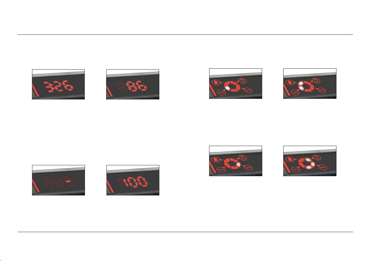
3.5 PAGlink batteries display their individual status, during charging,
on their built-in display. When using PL16 chargers, the characters
of the numeric display can be inverted, for legibility, with a single
button press. The display reverts automatically after removal from
the charger.
7
3. Charging
3.1 IMPORTANT: READ THE CHARGER HANDBOOK BEFORE ATTEMPTING TO
CHARGE THE BATTERY.
3.2 The following PAGlink chargers will charge PAGlink V-Mount batteries,
individually or linked, regardless of their capacity or state of charge:
The following chargers will charge PAGlink V-Mount batteries
individually or linked (batteries must be within 40% state-of-charge
of each other to be charged fully):
Constant-voltage V-Mount Li-Ion chargers of other reputable
manufacturers are also suitable.
3.3 The batteries incorporate a temperature sensor which will inhibit
charging if their temperature is below 0°C. See Section 2
Specification for the charging temperature range of PAGlink
batteries.
1 x 150Wh battery 3 hrs 45 mins
2 x 150Wh batteries 4 hrs 30 mins
4 x 150Wh batteries 9 hrs
6 x 150Wh batteries 13 hrs
8 x 150Wh batteries 18 hrs
16 x 150Wh batteries 36 hrs
1 x 96Wh battery 2 hrs 30 mins
2 x 96Wh batteries 3 hrs
4 x 96Wh batteries 6 hrs
6 x 96Wh batteries 9 hrs 30 mins
8 x 96Wh batteries 11 hrs 45 mins
16 x 96Wh batteries 24 hrs
9707 PAGlink PL16 Charger 2-positions, 8 batteries on each
9711 PAGlink PL16+ Charger 4-positions, 4 batteries on each
9708 PAGlink Cube Charger 4-positions, 2 batteries on each
9713V PAGlink Micro Charger 1-position, 4 batteries in total
9710 PAGlink Micro Charger 1-position, 4 batteries in total
9702VR PAG RMC4X Charger 4 positions, 4 batteries on each

8
4. Discharging
4.1 The batteries incorporate a precision fixed end-of-discharge cutoff set
to 12.5V, as measured by the battery. This cutoff will only operate if
the battery capacity is less than 5%, eliminating unwanted operation
due to high current and low battery temperature.
4.2 The maximum continuous discharge current for a single PAGlink
V-Mount battery is 8A. The batteries incorporate a current limit, and
consumption above this for more than 5 seconds will trigger the over-
current protection, turning the battery output off.
4.3 If the battery is discharged at too high a rate, even momentarily, the
protection circuit may be triggered, disconnecting the battery output.
It can be recovered by simply removing it from the load and pressing
the display button, provided the battery still retains some charge.
4.4 Where total continuous consumption is above 8A, two or more PAGlink
batteries should be linked. This will increase the maximum continuous
discharge current to 12A, provided the batteries are in a similar state
of charge.
4.5 The battery may be discharged within the temperature range -20°C
to +50°C, but for optimum performance, +10°C to +40°C is
recommended. The operating time will be shorter in conditions of
low temperature, and discharging will be electronically inhibited if
the battery temperature is below -20°C.
4.6 When the battery has been discharged at a high rate it will become
warm, and it is advisable to let it cool before charging it.
4.7 Computer Reset
The battery features a computer reset function. In exceptional
circumstances, a computer reset may be required. This is achieved by
holding the display button in for 20 seconds.

9
5. Storage
5.1 For the short term, PAGlink batteries can be left stacked on a charger
until required; the charger will keep them topped-up ready for use.
5.2 For long-term storage, batteries should be in a half-charged state
(between 20% and 80%), and unlinked. Storing batteries linked
accelerates the rate at which they self-discharge.
5.3 After 2 weeks of inactivity, a PAGlink battery will automatically enter
Sleep Mode, which greatly reduces its rate of self-discharge. It can be
woken prior to use by pressing the display button twice, by linking 2
batteries or by connecting it to a charger.
5.4 Batteries should be stored in a cool, dry place at a temperature
between 0°C and +20°C. Long-term storage outside of this temperature
range may reduce the battery’s life. Maintenance charging is not
required during long term storage.
5.5 After storage it is advisable to fully-charge batteries before use.

10
6. Run-Time, Capacity & Data
6.1 The Numeric Display:
The battery is able to display a numeric run-time prediction against
load, and charge status as a percentage.
(1) When connected to a camera that is turned on, two presses of the
battery’s display button will show a predicted run-time against the
given load, expressed in hours and minutes. When batteries are linked
the run-time displayed relates to the total for the connected
batteries.
(2) A single button press of the display, off or on-load, shows a
percentage figure of available capacity. When the batteries are linked
this figure still relates to the battery’s individual capacity.
(3) When battery capacity drops below 5% the display will indicate
that the battery should be charged as above.
(4) When the battery is fully charged the display will indicate 100%.
6.2 The 5-Light Display:
The battery is able to indicate a run-time prediction, against load,
and charge status as a percentage.
(5) When connected to a camera that is turned on, two presses of
the battery’s display button activates the time display. The ‘HRS’ LED
will flash twice.
(6) The number of hours will then be indicated by the number of lit
segments: each light = 1 hour.
(7) The ‘MINS’ light will then flash twice.
(8) The number of minutes will be indicated by the number of lit
segments: each light = 10 mins. When batteries are linked the run-
time displayed relates to the total for the connected batteries.
12
4
3
56
78

11
6. Run-Time, Capacity & Data
(9) A single button-press, whether the battery is on or off-load,
displays charge status in terms of percentage. When batteries are
linked this figure still relates to the battery’s individual capacity.
The lights indicate remaining capacity in percentage blocks:
6.3 In-Viewfinder Battery Status
Battery status can be shown as a percentage of available capacity in
the viewfinder/LCD of cameras designed to accept this data. Different
data standards are used by camera and battery manufacturers. PAGlink
V-Mount batteries automatically adjust the data output standard to
support SMB (Sony) and I2C (IDX).
When the batteries are linked, the data displayed in the viewfinder/
LCD is for the combined capacity available.
Red Cameras and Reversed SMB
PAGlink V-Mount batteries can be programmed easily by the user to
provide capacity data in the viewfinder of Red cameras that use the
reversed SMB data protocol.
Press the display button twice, and hold down on the second press
until ‘RED’ appears (on the numeric display) or until the top 2
segments are lit (5-light indicator). This indicates that the battery is
now compatible with the reversed SMB data protocol. When the
battery is connected to a camera with a different data protocol it will
automatically adjust to communicate with that system. To return to
reversed SMB, repeat the two-button-press process.
9
80 - 100% remaining
60 - 79% remaining
40 - 59% remaining
20 - 39% remaining
10 - 19% remaining
1 Flashing = 0 - 10% remaining

12
6. Run-Time, Capacity & Data
6.4 PAG Numeric Display Data Output
Data stored in the battery’s microprocessor can be revealed using the
battery display.
Press display button
x3 in 1 sec intervals &
hold for data mode
Release to see 1st
menu item: ‘Pd’
(voltage)
Press & hold for
3 seconds to see
voltage reading
Press without holding
for 2nd menu item
Press & hold for temp-
erature in degrees
celsius
Press twice
without holding
for 3rd menu item
Press & hold for
number of charge/
discharge cycles
Press x3without
holding for software
version
Press & hold for
version number...
Press x4 for
computer reset
Press & hold to perform
reset & do not release
until 3 lines disappear
...which appears in
2 parts indicating
version 5.7
After selecting to view the software version number, the battery will enter
Sleep Mode automatically. Sleep Mode reduces battery self-discharge and can
be used when you are going to store or ship your batteries. To exit Sleep
Mode or ‘wake’ the battery, press the display button twice, link 2 batteries or
connect the battery to a charger.

6. Run-Time, Capacity & Data
6.5 PAG 5-Light Display Data Output
Data stored in the battery’s microprocessor can be revealed using the
battery display. The display lights indicate numbers 0-9 in the
following way:
13
Press once without
holding to select 2nd
menu item: Tempera-
ture
Press & hold to see
temperature in degrees
celsius. This indicates
2...
...this indicates 5.
Therefore it reads
25°C.
2. Temperature in degrees Celsius
0123
4567
89
Data Mode: press the display button 3 times, in 1 second intervals,
and hold on the third press to enter data mode. All 5 lights will
flash:
Release to select
1st menu item:
Percentage State
of Charge
Press & hold for
3 seconds to see
reading for % SoC.
This indicates 9...
...this indicates 5.
Therefore it reads
95% charged.
1. Percentage State of Charge

14
6. Run-Time, Capacity & Data
Press x3 without
holding to select
4th menu item:
Software Version
Press & hold to see
version number.
This indicates 1...
...this indicates 9.
Therefore it reads
Version 1.9.
4. Software Version 6.6 PAGlink Battery Reader
The PAGlink Battery Reader is an accessory that can be used to display
data stored in the battery’s microprocessor via an easy to understand
numeric display. When connected to the battery contacts it will
provide information that is beneficial for managing your batteries:
Reader Menu:
1. State of charge as a percentage
2. Available capacity in ampere-hours
3. Cell temperature in degrees Celsius
4. Number of charge/discharge cycles
5. Voltage
6. Full capacity in ampere-hours
7. Date of birth (manufacture)
8. Software version
9. Serial number
Press x4 without
holding to select
5th menu item:
Reset Function
Press & hold to perform
reset & do not release
until all lights turn-off.
5. Reset Function
After selecting to view the software version number, the battery will enter
Sleep Mode automatically. Sleep Mode reduces battery self-discharge and can
be used when you are going to store or ship your batteries. To exit Sleep
Mode or ‘wake’ the battery, press the display button twice, link 2 batteries or
connect the battery to a charger.
Press x2 without holding
to select 3rd menu item:
Charge/Discharge Cycles
Press & hold to see
number of cycles.
This indicates 3...
...this indicates 6.
Therefore it reads
36 cycles.
3. Number of Cycles (Charge/Discharge)

15
7. Battery Protection Features
7.1 Over-charge Protection
Charging will be inhibited if the battery voltage exceeds a pre-set
level.
7.2 Over-discharge Protection
When the battery voltage reaches 12.5V, discharging is inhibited.
7.3 Over-current Protection
If a single battery is subjected to a current greater than 8A, but less
than 15A, the output will be turned off after 5 seconds. If the
current is greater than 15A, the output will be turned off immedi-
ately. In either case, the battery display will be inoperative and there
will be no voltage available at the terminals. The battery can be reset
by removing it from the load and pressing the display button.
7.4 Thermal Protection
Software protection inhibits charging if the battery temperature is
below 0°C. Return the battery to the charger when the battery
temperature rises above 0°C.
Software protection inhibits discharging if the battery temperature
falls to -20°C, or if it rises to +70°C. The output can be restored
when the battery temperature becomes within the specified range by
pressing the display button.
A thermal fuse is incorporated within the battery construction as a
‘backstop’ protection device, and this cannot be reset. In the unlikely
event of this fuse operating, please contact PAG or your dealer.
7.5 Construction
The battery cases consist of high-impact injection mouldings,
designed to protect the cells from impact damage.
The circuits are coated, making them resistant to electrolyte and
ensuring the operation of the safety systems in the event of damage
to the battery.
Internal wiring is rated for high current and high temperature, and is
double-insulated for added safety and protection.

16
8. PAGlink Features
8.1 Linking Batteries:
Align the V-Mount connectors and push the battery down until you
hear a click, indicating that the lock is engaged.
To release the battery, hold down the release button (1) and slide the
battery up (2).

17
8. PAGlink Features
Base Terminals
8.2 PAGlink batteries can be linked to combine their capacities, for
example, two 96Wh batteries provide 192Wh, and 3 offer 288Wh.
Two 150Wh batteries offer 300Wh when linked. Batteries of any rated
capacity, in any state of charge, can be linked for charge or
discharge. Linking batteries also increases the maximum continuous
current draw capability from 8A to 12A, provided they are in a similar
state of charge.
The maximum number of PAGlink batteries that may be linked has
been limited to 8. If more than 8 batteries are linked, the manage-
ment system will shut-down the supply, and no current will flow.
Front
Terminals
PAGlink V-Mount Terminals:
Rear
Terminals

18
8. PAGlink Features
Linked batteries form a network which allows communication between
batteries, ensuring that a safe protocol is followed under all
circumstances. The PAGlink management system elects the battery
with one or more connected to its front contacts to be the ‘master’
and ensures that this battery is always active (but not necessarily
delivering current). The system makes the most efficient use of the
energy available, and prevents a transfer of charge between batteries.
As discharge progresses, batteries are electronically added to or
subtracted from the bus bar to deliver the current required. The
status of individual batteries and total run-time can be viewed via
the battery displays. As long as the ‘master’ remains connected,
batteries may be added to or removed from the stack (hot-swapped)
in order to achieve continuous running.
NOTE: When not in use, batteries should be kept in an unlinked state
to ensure a lower self-discharge rate.

19
9. Safety Information
10.1 PLEASE READ THESE IMPORTANT SAFETY INSTRUCTIONS BEFORE
USING THE BATTERY AND RETAIN THEM FOR FUTURE REFERENCE.
When used correctly, Lithium-Ion batteries are a rugged and safe
method of storing power. However, incorrect treatment of the battery
could present a hazard. In the interest of safety, and the protection
of our environment, please read and observe the following health and
safety information.
WARNING:
Do not drop, throw, puncture, crush or incinerate the battery. Severe
mechanical abuse of the battery could result in damage to the cells,
and short-circuit internal to the battery. Li-Ion cells can deliver
power at very high rates. Arcing, excessive heat and the liberation of
combustible gas could result, with the potential for personal injury
or ignition of adjacent flammable materials.
Do not short-circuit the battery.
Keep the battery away from fires, strong sunlight and excessively
hot environments.
Avoid getting the battery wet and do not use it if it has been
immersed in water.
Do not attempt to disassemble the battery. Refer faults to authorised
service personnel.
Do not continue to use the battery if there is any change in the
appearance of the casing.
CAUTION:
The battery electrolyte is an alkaline solution, which can cause
chemical burns to human tissue. Leakage can occur as a result of
severe damage to the battery. Wear protective gloves when handling
all contaminated materials. In the event of contact with the skin,
flood copiously with clean water. If significant amounts of electrolyte
are involved, or if any has touched the eyes, seek immediate medical
attention.
ELECTRIC SHOCK: This symbol appears where the informa-
tion relates to the risk of electric shock.
WARNING: This symbol appears where the information
relates to an issue of personal safety.

10.1 The PAGlink V-Mount rear latching mechanism is separate to the
sealed battery case and can be replaced by the user in the event of
damage. Parts and instructions can be obtained from PAG Ltd. or an
authorised PAG service centre.
10.2 Customers should not attempt to open the sealed battery case for
repair or any other purpose. Unauthorised servicing invalidates the
battery guarantee and its air safety status (IATA).
If a fault develops, please contact a PAG service centre to receive a
fault diagnosis. Batteries that require further analysis must be
returned to your nearest PAG service centre. Li-Ion batteries are
classified as dangerous goods and cannot be returned without prior
contact. A consultation will be provided, followed by an estimate,
prior to any repair.
Authorised PAG Service Centres:
Europe & Middle East: Aspectra B.V.
Spoorhaven 78, 2651 AV, Berkel en Rodenrijs, Netherlands
UK & RoW: PAG Ltd.
565 Kingston Road, Raynes Park, London SW20 8SA, UK
The Americas: PAG America (a division of Carr Distribution Group)
18 Center Street, Ramsey, NJ 07446, USA
10. Servicing
20
This manual suits for next models
7
Table of contents
Other PAG Camera Accessories manuals