Timan VPM-3400 User manual

Congratulations on your sale of another VPM-3400.
You are delivering a quality product to your customer that comes with a
guarantee from the factory, and the guarantee period begins on the date of
delivery. Therefore, we kindly ask you to complete the below information
and send or fax it to the factory. This will allow us to always be able to assist
you in the best possible way.
Dealer: ___________________________ Date of delivery: ____________
Customer: ___________________________________________________
Customer’s address: ____________________________________________
Postal code: ________ Phone number: _________________________
Identification number of the machine:
_______________________________________
IMPORTANT – IMPORTANT – IMPORTANT
-IMPORTANT
FOR THE DEALER
GUARANTEE REGISTRATION
TIMAN A/S
Fabriksvej 13 ⋅DK-6980 Tim ⋅Phone +45 97 330 360 ⋅Fax +45 97 330 350
E-mail: timan@timan.dk ⋅www.timan.dk ⋅CVR: 27609627

OPERATOR'S MANUAL
SERVICE BOOK
VPM – 3400
Original operator's manual
Applies to model RC-750 with type/serial number: V34-000-01 - V34-000-02


VPM 3400


OPERATOR'S MANUAL
SERVICE BOOK
DIAGRAMS
RADIO
OPERATOR'S MANUAL
SPARE PARTS CATALOG

OPERATOR'S MANUAL
SERVICE BOOK
VPM –3400
Original operator's manual
Applies to model RC-750 with type/serial number: V34-000-01 - V34-000-02

CONTENTS
CONTENTS
1MACHINE IDENTIFICATION DATA ............................................................................2
TYPE LABEL ............................................................................................................................2
1.1 ORDERING SPARE PARTS:.............................................................................................3
2SAFETY RULES ...............................................................................................................4
3INTENDED USE OF THE MACHINE.............................................................................6
3.1 WEIGHT TABLE FOR USING TOOLS AND ACCESSORIES..................................................6
3.2 TOWING POLE (DRAWBAR) ..........................................................................................6
3.3 THE PERMISSIBLE LOAD ON THE FRONT OF THE MACHINE............................................7
3.4 PERMISSIBLE LOAD ON THE REAR END OF THE MACHINE..............................................8
3.5 MAXIMUM PERMISSIBLE SIDE LOAD OF THE MACHINE .................................................9
4SAFETY RULES FOR MAINTENANCE AND ADJUSTMENT .................................10
5EXPLANATIONS FOR THE WARNING SIGNS .........................................................12
6GUARANTEE STIPULATIONS FOR THE VPM-3400................................................13
7NOISE (SOUND PRESSURE) AND VIBRATIONS .....................................................15
7.1 SOUND PRESSURE MEASUREMENT .............................................................................15
7.2 MEASURING VIBRATIONS...........................................................................................15
8MACHINE CONSTRUCTION........................................................................................16
9STEERING COLUMN, LIGHTS, CAB AND CEILING SWITCHES ..........................16
9.1 STEERING COLUMN....................................................................................................17
9.2 ARMREST...................................................................................................................18
9.3 CAB...........................................................................................................................19
9.4 CEILING SWITCHES ....................................................................................................20
9.5 EXPLANATION OF CONTROLS AND SWITCHES.............................................................20
9.6 SEAT..........................................................................................................................23
10 MAIN SWITCH, FUSES AND RELAYS.......................................................................24
10.1 MAIN SWITCH ............................................................................................................24
10.2 MAIN FUSE WITH TWO RELAYS ..................................................................................24
10.3 FUSES IN THE CAB......................................................................................................25
10.4 FUSES FOR THE FUNCTIONS OF THE STEERING COLUMN AND ARM REST .....................25
10.5 RELAYS .....................................................................................................................26
11 DIESEL MOTOR OPERATION .....................................................................................27
11.1 STARTING AND STOPPING THE DIESEL MOTOR............................................................27
11.2 STARTING WITH AN AUXILIARY BATTERY AND RECHARGING THE BATTERY ..............28
11.3 INSPECTION WHEN DRIVING.......................................................................................28
11.4 COOLING WATER .......................................................................................................28
11.5 FUEL..........................................................................................................................29
11.6 EXHAUST GAS COLOUR..............................................................................................29
11.7 STOP THE MOTOR IMMEDIATELY IF............................................................................29

CONTENTS
12 MACHINE OPERATION................................................................................................30
12.1 USING THE NEW MACHINE .........................................................................................30
12.2 START DRIVING..........................................................................................................30
12.3 STOP DRIVING............................................................................................................30
12.4 TOWING.....................................................................................................................30
12.5 STARTING AND STOPPING ATTACHED TOOLS (ATTACHMENTS)...................................31
ATTACHING TOOLS TO THE LIFTING ARM...............................................................................31
12.6 ATTACHING TOOLS TO THE MOTOR COVER ................................................................32
12.7 SAFETY MEASURES WHEN DRIVING WITH A CENTRIFUGAL SPREADER........................32
13 DRIVING TIPS................................................................................................................33
13.1 GAS PEDAL ................................................................................................................33
14 DIESEL MOTOR MAINTENANCE...............................................................................33
14.1 FUEL..........................................................................................................................33
14.2 MOTOR OIL................................................................................................................34
14.3 CHANGING THE MOTOR OIL FILTER............................................................................35
15 RADIATOR MAINTENANCE.......................................................................................36
16 AIR FILTER MAINTAINENCE.....................................................................................37
16.1 MOTOR SUCTION FILTER...................................................................................37
16.2 POLLEN FILTER IN THE CAB........................................................................................37
17 BATTERY MAINTENANCE .........................................................................................38
18 SERPENTINE FAN BELT MAINTAINENCE ..............................................................39
18.1 ADJUSTING AND TIGHTENING THE SERPENTINE BELT.................................................39
18.2 TENSION REGULATION...............................................................................................39
19 HYDRAULIC OIL AND FILTER MAINTAINENCE...................................................40
19.1 OIL LEVEL INSPECTION ..............................................................................................40
19.2 HYDRAULIC OIL FILTER .............................................................................................40
20 WINDSHIELD WASHER FLUID MAINTAINENCE...................................................41
21 WHEEL AND TIRE MAINTAINENCE.........................................................................41
22 ADDITIONAL EQUIPMENT.........................................................................................42
23 LUBRICATION PLAN....................................................................................................43
24 DAILY INSPECTION .....................................................................................................45
25 TECHNICAL DATA .......................................................................................................46
26 EC DECLARATION OF CONFORMITY FOR VPM 3400...........................................47

INTRODUCTION AND SAFETY
1
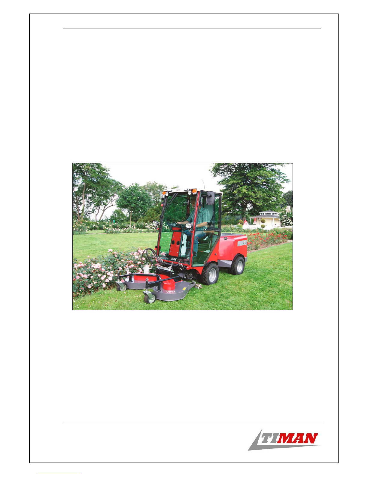
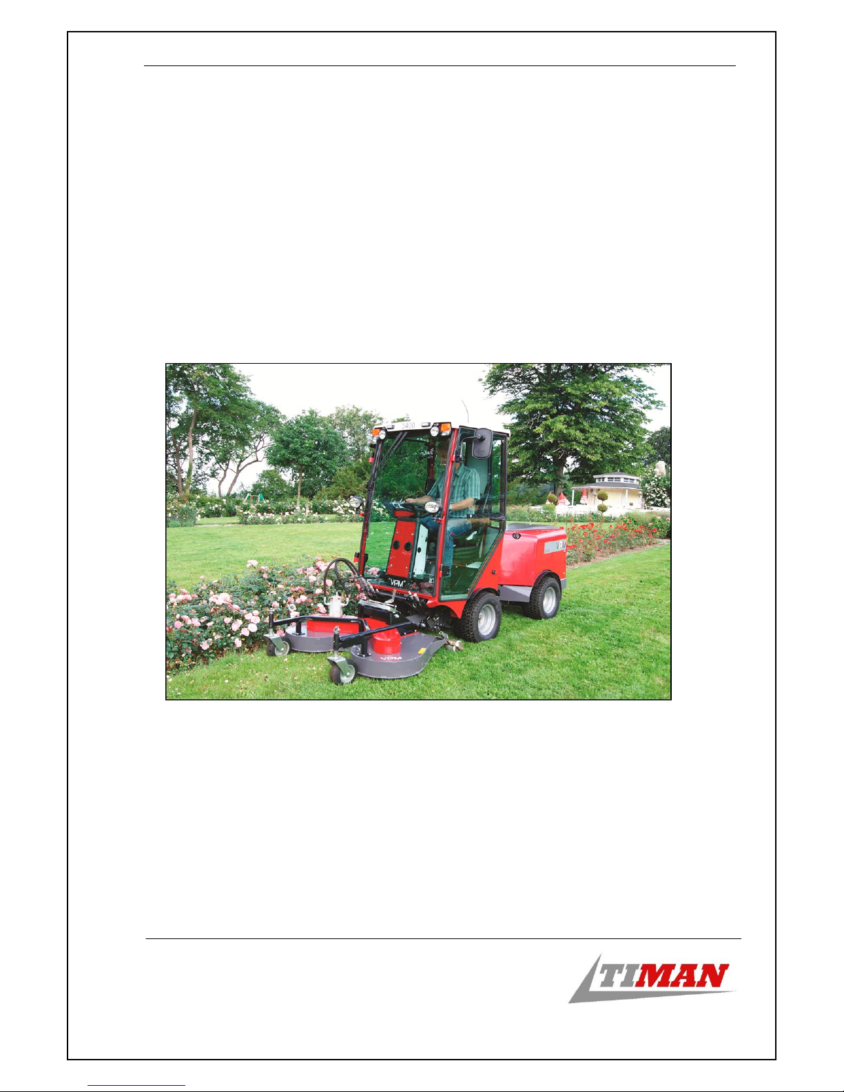
Congratulations on your new TIMAN VPM-3400
This operator's manual will assist you in the proper use, adjustment and maintenance of your
new machine.
Before you start to drive or work with the new machine, read this operator's manual
thoroughly, in particular the section on safety rules.
The indications right and left in the manual and in spare parts lists is the machine seen from
behind in the driving direction.

INTRODUCTION AND SAFETY
2
1MACHINE IDENTIFICATION DATA
Manufacturer: Timan A/S
Fabriksvej 13
6980 Tim
Tel.: +45 97 330 360
Fax: +45 97 330 350
Seller (to be completed by the seller)
Title / Name
Address
Zip code
State/country
Telephone
Type label
Year Production year: e.g. 2014
Identification number: Type –serial –machine number
For example: V34-000 –01 –1001

INTRODUCTION AND SAFETY
3
1.1 Ordering spare parts:
Your dealer will be more than happy to help you maintain your new machine in order for you
to be able to enjoy it as much as possible. After carefully reading these user instructions, you
will find that you can carry out some of the servicing yourself. However, if spare parts or
additional service is needed, contact the Timan dealer from whom you have purchased the
machine or the nearest authorized Timan service.
For faster sending and preventing incorrect packages when ordering spare parts, please
provide the following information:
The identification number of the machine: ________________________________
The motor serial number:_________________________
Spare part number and amount of parts required
Delivery method
The motor serial number is on the valve cover. The machine type label is on the right
protective cover under the driver's cab. The vehicle identification number is stamped onto the
protective cover on the right under the hydraulic tank. Find these numbers and write them
above on the front page of the catalogue.

INTRODUCTION AND SAFETY
4
2SAFETY RULES
IF THIS SYMBOL APPEARS IN THE MANUAL, IT CONCERNS YOUR
SAFETY
The user is responsible for mounting the protective cover, overall use of the safety equipment
and compliance with all safety provisions.
During transportation over public roads, the driver is responsible for ensuring that the
machine is assembled with all the equipment required by the laws of the given country and
that it is driven in accordance with the relevant laws and regulations (legislation) of the
country.
Driving carefully is the best way to prevent accidents. Read this chapter carefully before you
start using the machine. All drivers, regardless of their level of experience, are required to
read this manual and other related operating instructions before they start using this machine
and its tools (attachments). The owner is responsible for giving all the drivers training on safe
driving.
The safety rules are for ensuring your safety - therefore DO NOT FORGET:
1. Inform everyone who is unfamiliar with the safety rules and will be working with or
near the machine about the safety rules.
2. Never start the machine before you are clear about your plan and intention.
3. Never start the machine before mounting and closing all protective covers.
Immediately replace or repair missing or damaged protections.
4. Make sure all persons in the near vicinity of the machine keep a minimal distance of 5
m if the machine is running and working.
5. Turn off the motor and wait for the machine to stop running completely. Before
cleaning, lubricating, adjusting or repairing the machine, remove the key from the
ignition (start switch) and turn the main switch to the OFF position.
6. If a tool is mounted on the machine, the blocking (locking) device on the quick hitch
must always be turned on.
7. Other passengers must never be present on the machine or in the driver's cab.
8. Never leave the machine without turning off the motor and removing the key from the
ignition (and the parking brake must be activated).
9. You must not place any objects into the machine that can block its functions.
10. Never wear loose clothing when working with the machine and keep a safe distance
from its rotating parts.
11. The machine must never be used to transport people, and only one person may be in the
cab.

INTRODUCTION AND SAFETY
5
12. Beware of hot surfaces and exhaust gases due to burn hazards.
13. Do not touch working parts of the machine.
14. Keep the motor area clean and free of dust to prevent the possibility of fire.
15. Only open the motor area when the motor is off.
16. Before driving on public roads, make sure all the headlights and signal lights work and
are in place.
17. Never handle open fire near the tank for diesel and oil, in particular when it is being
filled.
18. Never leave the motor running in a closed space. Exhaust gas is dangerous and it can
cause death.
19. Never drive in places where the machine can skid or tip over. Drive slowly on inclined
planes (slopes). Never drive on inclined planes with a pitch angle greater than 15
degrees. If the machine tips over, hold the steering wheel firmly. Do not jump out of
the machine.
20. Do not use the machine or any of its tools under the influence of alcohol, drugs and
similar medicines or when fatigued.
21. Do not drive near ditches, holes, dams and other places in the terrain which can collapse
under the weight of the machine. The risk of tipping over is increased if the surface is
loose or moist.
22. Reduce pressure on the gas pedal in order to reduce speed when turning around and in
quick turns.
23. Take a good look where you are driving.
24. Look back before and during reversing. Make sure there aren't any holes, obstacles and
small children on the surface behind you. Pay extra attention if equipment, which blocks your
rear view, is attached to the machine.

INTRODUCTION AND SAFETY
6
3INTENDED USE OF THE MACHINE
VPM 3400 is a universal tool carrier that can perform many tasks depending on the type of
equipment attached to it. It could, for example, cut grass, sweep, cut live fences, remove
snow, salt roads etc.
The respective tools may be attached to the machine on the front and at the rear. Furthermore,
a combination of a fork and ball joint for towing tools and carts can be attached to the
machine.
VPM 3400 may drive on public roads, and it is intended for professional operators.
The use of the machine depends on its tasks.
However, you must ensure that the loads and weights specified below will never be exceeded.
Using accessories which exceed the maximum specifications specified below can lead to
malfunctions, machine failure, damage to someone else's property and injury to the driver
and/or other persons. The Timan guarantee does not cover any malfunctions or machine
failures caused by using non-corresponding accessories.
3.1 Weight table for using tools and accessories
Front axle Rear axle Maximum permissible
weight (total weight)
1300 kg 1300 kg 1860 kg
Towing pole (drawbar)
The maximum permissible load of the towing pole is specified
on the picture. It is important to ensure that the vertical load of
the towing pole is never greater than 120 kg (up/down). This rule
applies even if the vehicle is connected with a coupling head
and in the towing pole. If the vehicle is connected with a
coupling head (see Fig no. 1 and 2), the maximum permissible
weight (total weight) of the vehicle must be 1500 kg if it is
equipped with overrun brakes and 750 kg if it is not.
Alternatively, the towing pole may be loaded with the vehicle,
which is connected in the towing pole (see Fig no. 3). This may
be done with the maximum permissible weight (total weight)
of 1850 kg if the vehicle is equipped with overrun brakes. If the
vehicle is connected with a towing pole, it must be a four-wheel
vehicle (four-wheel drive) with a turntable steering axle
(see Fig. no. 4 and 5) which has a maximum permissible mass
(total mass) of 1850kg if it is equipped with overrun brakes
and 750 kg if it is not. Only towing poles approved by
Timan A/S may be attached.
1
2
5
4
3

INTRODUCTION AND SAFETY
7
3.2 The permissible load on the front of the machine
The maximum permissible load on the lifting arms is shown in the diagram below
The load must be positioned in the middle between the front wheels.
In the load table, point 0 is shown on the lifting arm handle if it is in a vertical (upright)
position. It is measured from the handle on the lifting arms where the quick coupler is
connected (quick coupler device).
For example, the arms may lift 150 kg with a load placed 800 mm away from handle without
loading the rear end. When minimal load amounting to 200 kg is on the rear end, the arms
may lift 300 kg at the same distance.
0
50
100
150
200
250
300
350
400
450
500
-800 -400 0 400 800 1200 1600 2000 2400 2800
Kg
mm
Přípustné zatížení vpředu žádné zatížení vzadu zatížení vzadu-min. 200 kg

INTRODUCTION AND SAFETY
8
3.3 Permissible load on the rear end of the machine
The maximum permissible load on the rear end of the machine and load platform is specified
in the diagram below.
Caption: Permissible load on the rear end of the machine
The load must be positioned in the middle between the rear wheels.
The maximum permissible load on the load platform is 600 kg above the centre of the rear
wheels.
The distance from centre of the rear wheels to the rear end of the machine is 600 mm.
For example, the rear end may carry a load weighing 400 kg with the centre of gravity
positioned 900 mm away from the centre of the rear wheels - 300 mm if the measurement is
taken from the rear end of the machine.
Important: It is necessary to use the original Timan A/S tool frame when loading the rear
end.
INTRODUCTION AND SAFETY
9
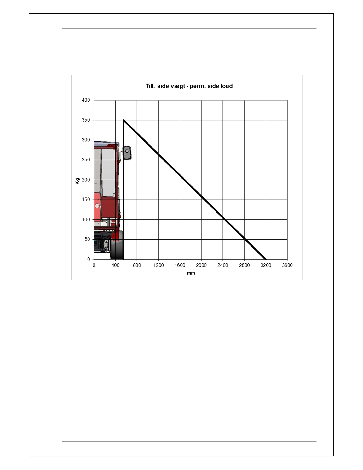
3.4 Maximum permissible side load of the machine
The maximum permissible side load of the machine is specified in the diagram below.
Caption: Maximum permissible side load of the machine
The mass table shows point 0 between the lifting arms and on the ball joint at the rear end of
the machine (if it is attached).
Equipment for side loading may either be fixed to the front on the lifting arms or to the rear.
The stated load is on the lifting arm holder or the rear end of the machine. If the tool is fixed
further away than the holder, on the rear end of the machine, the weight that can be suspended
from the machine decreases.
Important:
-Only one side load may be suspended from the machine at a time.
For example, the machine may carry a load weighing 200 kg with the centre of gravity
positioned 1700 mm away from the centre of the lifting arms.
Table of contents


