Timbertech DeckLites Operating and safety instructions

SEPTEMBER 2012
RAILING &
DECKLITES
®
INSTALLATION &
MAINTENANCE GUIDE
DECKING
RAILING
LIGHTING
ACCESSORIES www.timbertech.com

3
Dear Valued Customer:
TimberTech focuses on quality, innovation and brand in all that we do. With
an assortment of plank profiles, industry leading railing systems, fencing and
numerous accessories, building beautiful decks has never been easier.
TimberTech is committed to providing builders and professional deck installers
with exciting new products our customers demand, as well as programs and
support material to differentiate themselves in the marketplace.
TimberTech is a member of the Crane Building Products family of companies, which
is part of the Crane Group, a more than 60-year old family owned company.
TimberTech has compiled this Railing & DeckLites®Installation & Maintenance
Guide to provide a thorough resource for technical information for our railing systems
and deck lighting system.
To get information on other TimberTech products visit timbertech.com or ask your
dealer for these installation guides:
• TimberTech Decking & DrySpaceTM Installation & Maintenance Guide
• TimberTech FenceScape® Installation & Maintenance Guide
TimberTech would like to thank you for your interest in our railing systems.
We strive to better serve our customers and hope that you have a wonderful
experience with TimberTech.
Installing TimberTech
TimberTech offers a variety of innovative railing systems and inll options. A variety of color choices allow
you to match or complement your TimberTech deck planks.
TimberTech products are a revolutionary alternative to traditional wood-they don’t rot, warp or splinter-and they look great year after year.
And unlike wood, TimberTech products require no painting, staining or sealing.
Make sure your project meets local building codes before you begin installation.
These installation guidelines will direct you through the process of installing TimberTech railing systems. These methods are recommended by TimberTech but may
not cover every installation scenario you encounter. Since each installation is unique in its performance requirements, the ultimate installation method used is the
sole responsibility of the installer. TimberTech recommends that all designs be reviewed by a licensed architect, engineer or local building official before installation.
TimberTech Code Listings
ICC Evaluation Service, Inc.
ICC ESR-1400 • Ornamental Rail System
Underwriters Laboratories, Inc.
E351168 • DeckLites
ATI Architectural Testing, Inc.
CCRR-0114 • RadianceRail
CCRR-0129 • BuilderRail
Code listing for RadianceRail Express Pending
Test Reports:
ADA Hand Rail & Secure Mount Post System tested to requirements of
ICC-ES-AC-174
Once a product is tested by an independent lab, an application and report is
submitted to one of several agencies that provide listings for building products
that meet the requirements of Acceptance Criteria 174 (AC 174) as set forth by the
International Code Council Evaluation Service (ICC-ES). TimberTech currently has
listings from the ICC-ES and Architectural Testing Inc. The following TimberTech
reports on code compliance are available to download on www.timbertech.com.
For the most up-to-date code listings visit www.timbertech.com/
installation.
Contents
Care & Cleaning
Storage.................................................................................................................... 78
Ice & Snow Removal................................................................................................ 78
Removing Mildew & Stains...................................................................................... 78
RadianceRail Touch-Up........................................................................................... 78
ADA Compliant Hand Rail System
Component & Installation ..................................................................................79-80
Secure - Mount Post System
Component & Applications...................................................................................... 81
Composite & Concrete Installation.......................................................................... 82
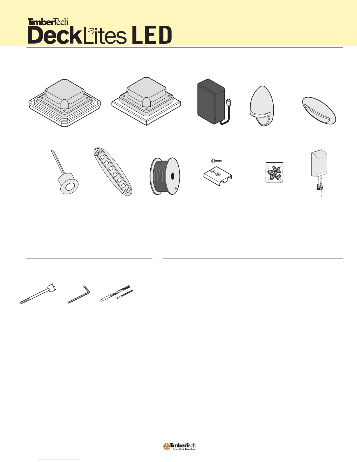
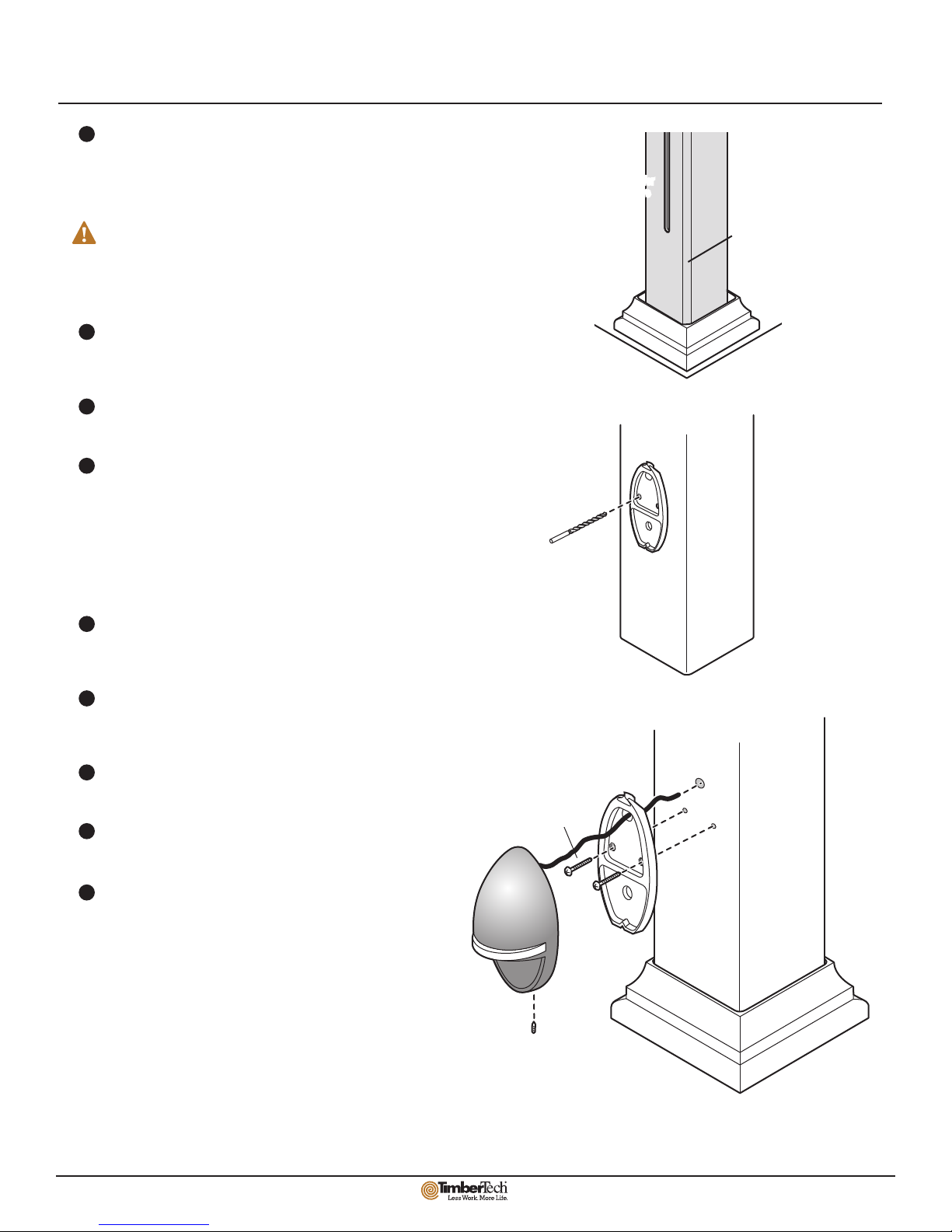
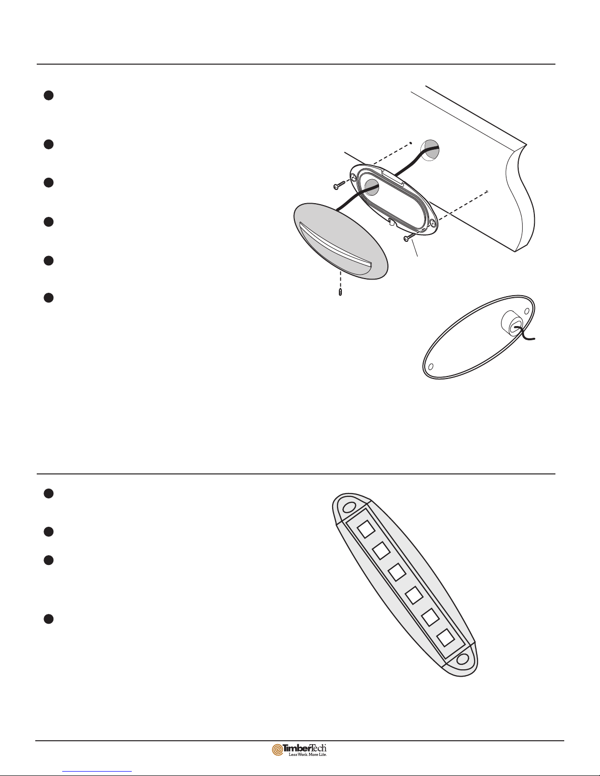
DeckLites®
General Information
Components........................................................................................................ 83
Tools Required..................................................................................................... 83
Safety Precautions.............................................................................................. 83
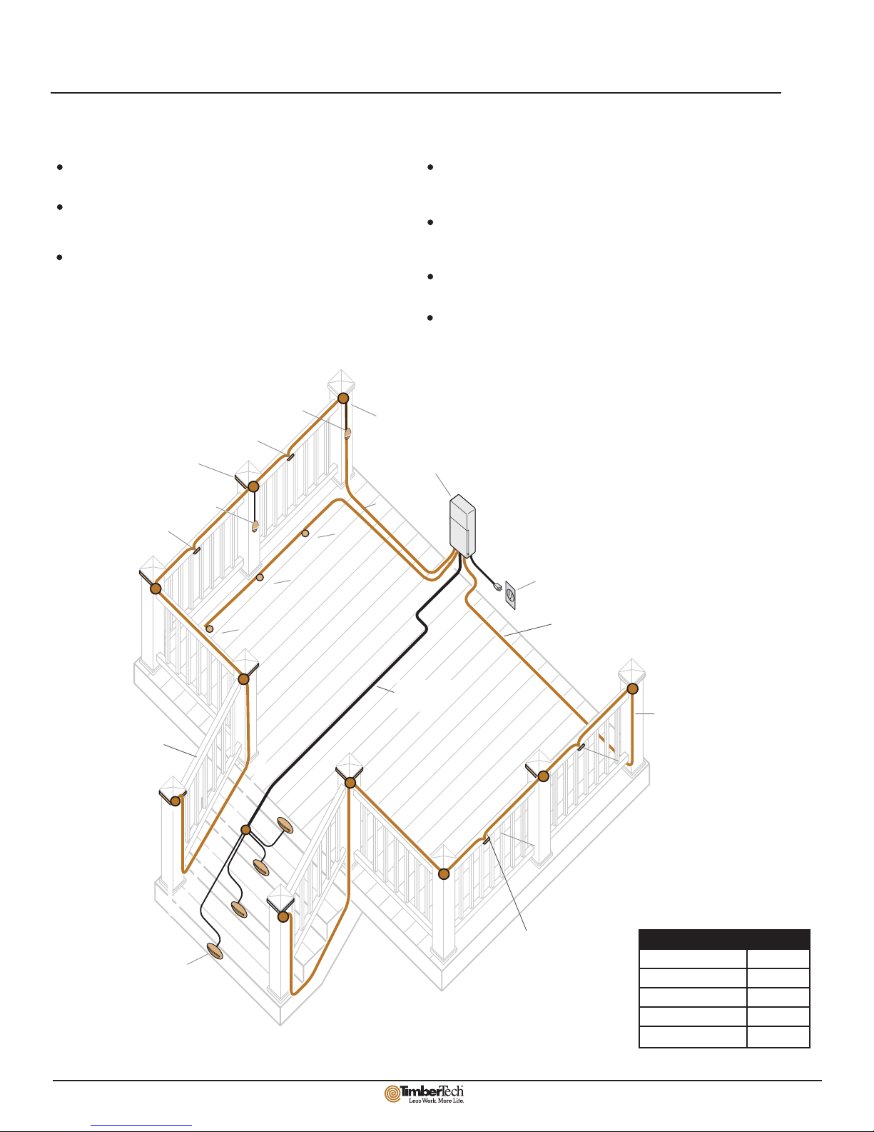
Installation Guidelines
Layout Overview.................................................................................................. 84
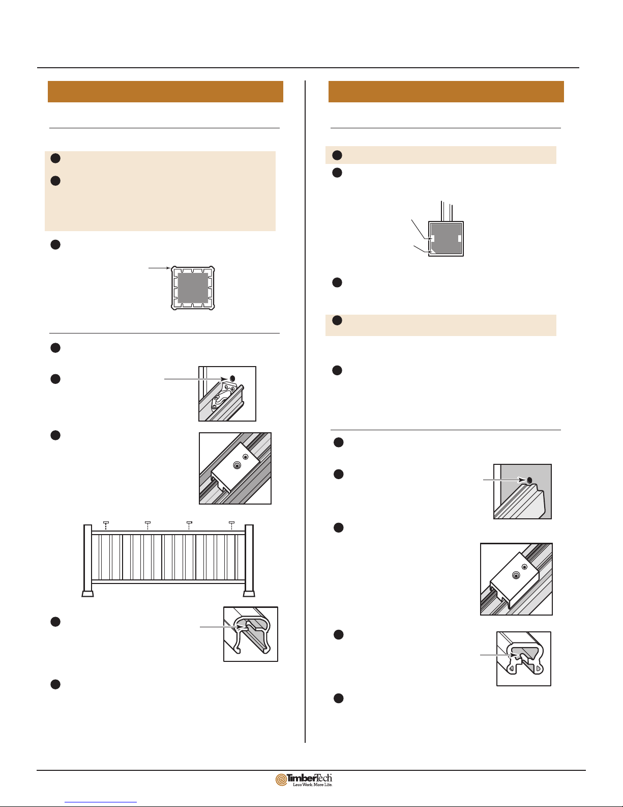
Wiring Instructions.........................................................................................85-86
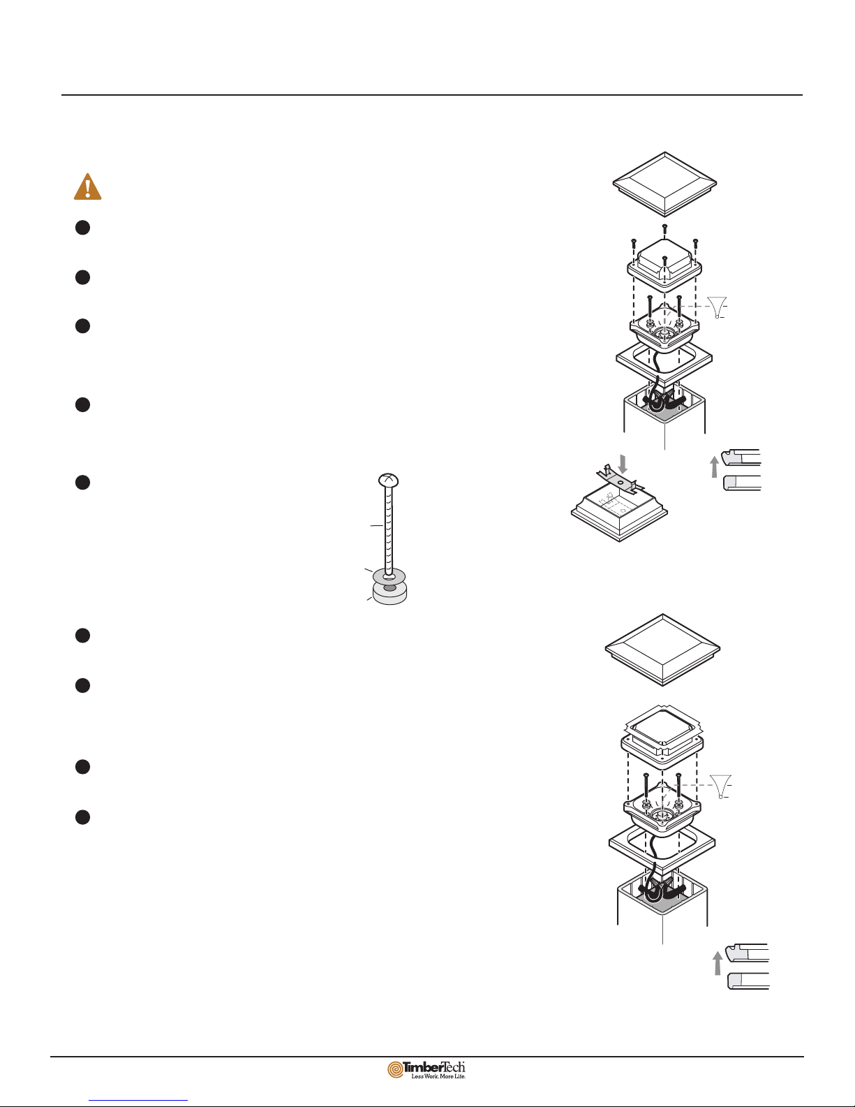
Component Installation..................................................................................87-90
Warranty
Warranty Information .........................................................................................91-94
Warranty Card ......................................................................................................... 95

83
For information about DeckLites®LED visit www.timbertech.com/DeckLites.
Visit www.timbertech.com/installation to view TimberTech installation videos.
DeckLites Components
1
Important Safety Precautions
INSTRUCTIONS PERTAINING TO A RISK OF FIRE OR INJURY TO PERSONS
IMPORTANT SAFETY INSTRUCTIONS
WARNING – To reduce the risk of FIRE OR INJURY TO PERSONS:
Turn off/unplug before servicing fixtures. Contact only switch/plug when
turning on.
Keep lamp away from materials that may burn.
Do not operate the luminaire fitting with a missing or damaged cover.
SAVE THESE INSTRUCTIONS
Stair Riser Light
Silicone Filled
Wire Nuts
(20/bag)
100W Transformer
16/2 AWG Wire
5 x 5 Post Lamp Module
RadianceRail
4 x 4 Post Lamp Module
Ornamental Rail, RadianceRail Express
Accent Light
In addition to a basic tool set, you will need the following
for installation of DeckLites components.
Drill Bits:
3/8”
7/64”
1/4”
3/16”
2.5mm
Allen Wrench
Spade Bits:
5/8”
3/4”
1”
1-1/2”
Tools Required
Cable Guide
& Screw
(12/bag)
®
In-Deck Light Under-Rail Light
PDF !"# "pdfFactory Pro" $#%&'( www.fineprint.cn
Dimmer*
*For installation instructions for the dimmer, visit http://www.timbertech.com/installation/installation-resources

84
The TimberTech DeckLites LED system is designed for use with the RadianceRail, RadianceRail Express and Ornamental Rail products.
Below is a sample lighting layout showing fixture placement and wiring routes. When laying out the wiring for your deck, keep the following in mind:
Building codes vary by locale, please consult all applicable codes
before beginning project.
Modifications must be made to railing components during assembly to
accommodate wiring and fixtures. Do not begin deck construction until
you have read the lighting instructions.
A maximum of 40W can be appliced to a single circuit. The maximum
recommended load for the transformer is 90 watts. Please refer to chart
below to determine that wattage of each fixture.
The 16AWG secondary supply wire can be buried to a maximum of 6” for
routing under deck or other obstacles. The Luminary (unit secondary)
wires cannot be buried underground.
Luminaries shall not be installed within 10 feet (1.52m) of a pool, spa or
fountain.
This unit secondary wiring shall be protected by routing in close
proximity to the luminaire or fitting, or next to a building structure
such as a house or deck. The wiring shall not be buried except for a
maximum 6 inches (15.2cm) in order to connect to the main
secondary wire. Trim post covers to correct length - see Post and Rail Prep page.
Post Cap Light Transformer
Wire routed
between post
and post cover
Wire Junction
Outdoor GFCI Outlet
Stair Riser Light
Wire routed
inside top
rail assembly
Wire cannot be
routed inside top
rail of stairs
Wire routed
under deck
Non-Looped
Circuit
Non-Looped
Circuit
Accent Light
Accent Light
Under-Rail Light
Under-Rail Light
Under-Rail Light
Under-Rail Light
In-Deck Light
In-Deck Light
In-Deck Light
16/2 AWG Wire
TimberTech DeckLites LED Layout Overview
Fixture Wattage
Post Cap Module 3.0W
Accent 1.6W
Under Rail 1.5W
Stair Riser 1.3W
In-Deck .5W

85
Wiring Instructions
Connections between the main 16/2AWG cable and the lighting fixtures are made using
the space between the post and the Post Cap or Post Light Module as a junction box.
When routing the main wire around the deck, leave a loop of extra wire at the top of
each post to allow for splicing connections.
Use silicone filled wire nuts with corrosion protection and intended for outdoor use to
make all connections. They shall be copper, copper alloy,
or the equivalent.
Be sure to MAINTAIN POLARITY by aligning ridges when splicing the main
16/2AWG wires or shorting will occur. Polarity for the 18AWG fixture wires is not
critical.
When making splices, do not pre-twist wires. Pre-twisting wires can lead to a poor seal
inside the wire nut causing corrosion and/or voltage drop.
Wire Connections
Cross section of
16AWG wire
Ridges
Wire Polarity
NO
YES
Wire Nut Instructions
IMPORTANT: Turn off power before installing or removing connector. Product to be used in accordance with
local and national codes.
1. Strip wires 5/8”
2. Align frayed strands of conductors.
3. Do not pre-twist. Place stripped wires together with ends even, but lead smaller
stranded wires slightly ahead of larger solid or stranded wire.
4. Twist connector onto wires pushing firmly until hand-tight. DO NOT over torque.
5. Wipe excess sealant in and around conductors. DO NOT REUSE.
Use the following guidelines for correct usage of wire nuts.
3
Transformer Settings
Power is supplied to the lighting fixtures via 16/2AWG wires connected to the provided
transformer. One side of the 16/2AWG wire is connected to the Common terminal (C),
the other side is connected to an Output terminal. One side of the 16/2AWG wire
contains raised ridges to allow for easy identification (see Wire Connections section).
The maximum recommended load for the transformers is 90 watts.
Transformer Connections
Consult the instructions provided with the transformer for
additional information.
Outside
GFCI Circuit
Dimmer Instructions
On Turns unit on
100 Watt Transformer
Off Turns unit off
Auto Photocell Control “Auto” – Lights come
on at dusk and go off at dawn
4H
6H
8H
Stays on 4hours after dusk
Stays on 6hours after dusk
Stays on 8hours after dusk
PDF !"# "pdfFactory Pro" $#%&'( www.fineprint.cn
Female
Male
Male
Dimmer
Line Length 10’
Stripped
Antenna
Female Power from
Transformer
Install the Dimmer next to the DeckLites LED Transformer. Use the provided 10” wire and
water-tight connector to connect the Dimmer to the DeckLites LED Transformer. Next, use the
provided 10’ wire and water-tight connector to connect the Dimmer to main run of wire.
To use the Dimmer, turn the DeckLites LED Transformer to a setting that turns the DeckLites
on when desired. To dim the lights, press the button on the remote or on the dimmer until
the desired brightness is achieved.
The recommended load for the dimmer is between 20-90 watts.
Fixture Wattage
Post Cap Module 3.0W
Accent 1.6W
Under Rail 1.5W
Stair Riser 1.3W
In-Deck .5W

86
Post & Rail Preparation
Trim 4x4 wood posts to 35-1/2” above deck surface.
Trim Post Covers to length: 38” for a lit post
40-1/8” for an unlit post
For best results, use a miter saw with a fine toothed blade to
make Post Cover cuts. Check cuts for square.
Feed main 16/2AWG cable between post and Post Covers. (See
Wire Connections section for more info.)
Post & Post Covers
5 x 5: RadianceRail 4 x 4: Ornamental Rail, RadianceRail Express
Trim 4x4 wood posts to 34-1/2” above deck surface.
In order to provide clearance for wiring between the post and Post
Cover you must create a wire channel.
If you plan to install a post mounted Accent Light, you must rout a
slot down the post to the desired fixture position. (See Accent Light
instructions.)
Trim Post Covers to length: 36-7/8” for a lit post
39” for an unlit post.
For best results, use a miter saw with a fine toothed blade to make
Post Cover cuts. Check cuts for square.
Feed main 16/2AWG cable up or down post using prepared feature.
(See Wire Connections section for more information)
Post & Post Covers
Install Support Rails and Balusters as normal, DO NOT install Top
Rail yet.
Drill a 5/8” hole through the
Post Cover on centerline,
directly above rail Mounting
Blocks.
After running all wiring, secure four
Cable Guides to Support Rail using #8
x 3/4” screws. Use the Cable Guides to
pre-drill holes thru the Support Rail
with a 3/16” bit.
Attach Top Rails before installation of Post Cap Lights. Use the holes
that were pre-drilled through the Cable Guides to attach the Top
Rail. FAILURE TO USE THESE HOLES MAY RESULT IN WIRE DAMAGE. Attach Top Rails before installation of Post Cap Lights. Use the holes
that were pre-drilled through the Cable Guides to attach the Top Rail.
FAILURE TO USE THESE HOLES MAY RESULT IN WIRE DAMAGE.
Make a notch on the centerline of the Top
Rail by boring a 3/4” hole centered 1/2"
back from the end of the rail, then cut it
out to form an open slot.
Railing
Railing (Only for Ornamental Rail)
Chamfer the corner
of the post
Rout a 1/4” by 1/4”
slot down the post
Run wires up
corner voids
created by
Post Cover Ribs.
OR
(The following instructions are for a rail height of 36”) (The following instructions are for a rail height of 36”)
1
2
3
1
2
3
4
5
Install Universal Rails and Balusters as normal, DO NOT install Top
Rail yet.
Drill a 5/8” hole through the Post Cover on
centerline, directly above the Universal
Rail.
After running all wiring, secure four
Cable Guides to Universal Rail using
#8 x 3/4” screws. Position every 4th
Baluster, avoiding Balusters and
Baluster Mounting Blocks if installed.
Use the Cable Guides to pre-drill holes
thru the Universal Rail with a 3/16”
bit.
Make a notch on the centerline of the Top
Rail by boring a 3/4” hole centered 1/2”
back from the end of the rail, then cut it
out to form an open slot.
1
2
3
4
5
1
2
3
4
5
SCREW
HOLE
DRILL
THRU
3/16”
SCREW
HOLE
DRILL
THRU
3/16”
Cable Guide Placement
NOTE: Do not rout a wire
channel where a rail is to be
mounted.
x

87
Installing Post Cap Light
6
Post Lamps must be installed after the rail assembly has been completed.
Before installing, refer to Post & Rail Preparation
section.
1
2
3
4
5
6
7a
8
Install the Lens onto the Post Cover as shown.
Remove the Post Lamp Cover from the Post Lamp Bottom Housing.
Trim excess wire length and make wiring connections to 16/2AWG main
cable and other 18/2AWG luminary wires. Check to confirm polarity of
main cable connections.
Coil the connected wires inside the Post Cover and insert the Post Lamp
Bottom Housing into the Lens. Check to make sure no wires are exposed or
pinched between Lens and Bottom Housing.
Install the mounting screws and washers
assembled as shown. Watch as screws are
installed to ensure that wires are clear of
screw tip prior to driving them into the wood
post. Tighten only until the silicone washer
begins to compress. Over-tightening could
break the Bottom Housing causing perma-
nent damage.
Reinstall Post Lamp Cover and screws.
For 5x5: Install Cap Spring into Post Cap as shown (place finger and
thumb on Cap Spring tabs, flex gently until Cap Spring appears slightly
bowed, insert Cap Spring into Post Cap approximately at the center of the
opening until bowed back ends contact the inside top of the Post Cap then
relax finger and thumb pressure). Press Cap Spring intoseated position
as shown.
For 4x4 (Includes Gasket): Set gasket centered on post lamp cover.
Install Post Cap onto Post Lamp Cover.
Silicone
Washer
Metal
Washer
Base
Mounting
Screw
7b
Post Cap
Post Cap
(Cap Spring Installed)
Post Lamp Cover
Post Lamp
Bottom Housing
Post Lamp Lens
Post Cover
LED
Reflector
Cap Spring Tab
5x5
4x4
UP
Lens Orientation
Cap Spring Installation
7a
Post Cap
(Cap Spring Installed)
Post Lamp Cover
Post Lamp
Bottom Housing
Post Lamp Lens
Post Cover
LED
Reflector
5x5
4x4
UP
Lens Orientation
7b
Gasket

88
Installing Post Mounted Accent Light
1
2
3
4
5
6
7
8
9
Accent Light
Back Plate
Post Skirt
#8 x 3/4”
Screws
Accent Light
Cover
Accent Light wire channel must be routed during the installation of
the Post Cover. The Post Cover and the wood post must be prepared
in advance to accommodate installation of the Accent Light. (No
post preparation is necessary for RadianceRail.)
If using Ornamental Rail, RadianceRail Express or BuilderRail,
prepare the wood post by routing a 1/4” wide by 1/4“ deep wire
channel up the center of the post on the face where the Accent
Light will be mounted. For main cable, slightly bevel the corner
of the 4x4 post.
If a Post Skirt is used, install it over the wood post before
installing the Post Cover. You will not be able to install Post
Skirt after Post Cover and Accent Light are in place.
Remove Accent Light Cover from Accent Light Back Plate by
loosening Set Screw located at bottom of Accent Light Cover.
Prepare the Post Cover in the following manner:
• Cut the Post Cover to the desired length.
• Determine the height the Accent Light will be mounted.
• Mark the location of the wire hole and the mounting
screw holes using the Accent Light Back Plate.
• Drill a 3/8” hole for the wire and drill two 7/64” holes
for the mounting screws.
Route the Accent Light wire through the BackPlate then through
the wire hole in the Post Cover then invert the Post Cover and
allow the wire to extend out the top end of the Post Cover.
Hold the Accent Light Back Plate loosely in position and slide the
Post Cover over the wood post and into the Post Skirt. Make sure
the wire is in the routed wire channel.
Attach the Accent Light Back Plate to the post using two #8 x
3/4” screws provided.
Re-install Accent Light Cover and secure with Set Screw with
Allen Wrench.
Trim excess wire and make wiring connections.
(See Connections section of manual).
Routed Channel for
Accent Light Wire
Beveled Corner
for Main Cable
Set
Screw

89
Installing Stair Riser Light
Installing Under-Rail Light
Stair Riser Light
Housing
Stair Riser Light
Cover
Stair
Riser
#6 x 1”
Wood
Screw
Set
Screw
1
2
3
4
5
6
Locate and mark vertical and horizontal centerlines for Stair Riser
Light location. Level the back plate and secure using #6 x 1” wood
screws.
Use the back plate as a template to locate the center of the 1-1/2“
hole for the “bump out“.
Cut a 1-1/2” diameter hole at the center point using a 1-1/2”
spade bit.
Trim excess wire length and make wire connection to main circuit
wire using wire nuts provided.
Align the lighting “bump out” with the 1-1/2” hole and assure
alignment between the Stair Riser light and the back plate.
Secure housing to back plate using the set screw with a 2.5mm
Allen wrench.
1
2
3
4
Choose the location for the Under-Rail Light so it is centered in
the balusters.
Drill a 3/8” hole to feed the wire through the H Channel.
Feed the wire and mount the light to the recessed H Channel
making sure the light is tilted in (light comes with a 15˚ tilt which
is usually facing the deck). Use the center alignment beam for a
guide for the 2 screws. Use 8-3/4“ screw size.
Trim excess wire length and make wire connection to main circuit
wire using nuts provided.

90
Installing In-Deck Light
1
2
3
4
5
Locate and mark the centerline of the deck plank where the
in-deck light will be mounted.
On the desired point of the center line, use a 1” spade bit to
create a through hole (be sure not to drill into the substructure.)
Guide the light’s wire into the through hole.
Push the lighting fixture into the through hole until the flange
touches the deck surface.
The wire connections can then be made under the deck’s
surface.
In-deck light should be installed in a low foot-traffic area.
In-deck light can only be used when there is room under the deck to access the wires to make all of the connections

92
Statement of Warranty: This warranty is given to the original purchaser, residential or commercial, (“Purchaser”) of TimberTech DeckLites LED products (“DeckLites”.) This warranty does
not extend to fasteners that are not supplied by TimberTech.
TimberTech Limited (“TimberTech”) warrants to Purchaser that for a period of five (5) years from the date of original consumer purchase (the “Term”), under normal use and service conditions,
DeckLites will be free from defects in material and workmanship, and will not crack, peel, blister or corrode as a result of manufacturing defects.
All warranties are subject to the exclusions, limitations and restrictions set forth below.
Obtaining Warranty Performance: If Purchaser discovers a defect in the TimberTech Products during the Term, Purchaser must, within thirty (30) days from the discovery of the alleged
defect but no later than the end of the Term, notify TimberTech in writing, at the following address:
TimberTech Limited • 894 Prairie Avenue • Wilmington, Ohio 45177 • Attn: Claims Department
Purchaser must include in this notification proof of purchase and a statement explaining the defect. TimberTech may request additional information. After reviewing all information,
TimberTech will make a determination regarding the validity of such claim. If TimberTech determines that Purchaser’s claim is valid, TimberTech will, at its option, either replace the defective
TimberTech Products or refund the portion of the purchase price paid by Purchaser for such defective TimberTech Products (not including the cost of its initial installation). This warranty
shall not cover, and TimberTech shall not be responsible for, costs and expenses incurred with respect to the removal of the defective TimberTech Products or the installation of replacement
materials, including but not limited to, labor and freight. The foregoing remedies are the SOLE AND EXCLUSIVE REMEDY FOR BREACH OF ANY WARRANTY.
Transfer of Warranty: This warranty may be transferred one (1) time within the Term to a subsequent buyer of the property upon which DeckLites were originally installed. Transfer of this
warranty does not extend the Term of the warranty.
Exclusions from Warranty Coverage: TimberTech does not warrant against and is not responsible for, and no implied warranty shall be deemed to cover, any damage or loss attributable to:
(1) improper installation of DeckLites and/or failure to abide by TimberTech’s installation guidelines; (2) use of DeckLites in an application not recommended by the TimberTech installation
guidelines (including, but not limited to, immersion or submersion of the products in water) and local building codes; (3) any act of God (such as flooding, hurricane, earthquake, lightning
(or other incidences of excessive voltage), natural disaster, etc.), environmental condition (such as air pollution, mold, mildew, etc.), or staining from foreign substances (such as dirt,
grease, oil, etc.); (4) variations or changes in color of DeckLites; (5) normal weathering due to exposure to sunlight, weather and atmosphere which can cause colored surfaces to, among
other things, flake, chalk, or accumulate dirt or stains; (6) improper handling, storage, abuse or neglect of DeckLites by Purchaser, the transferee or third parties; (7) use in harsh industrial
or marine environments; or (8) any fasteners not supplied by TimberTech.
Purchaser is solely responsible for determining the effectiveness, fitness, suitability and safety of DeckLites in connection with their use in any particular application.
Limitations: DISCLAIMER OF WARRANTIES: EXCEPT FOR THE EXPRESS WRITTEN WARRANTY CONTAINED HEREIN, TIMBERTECH MAKES NO OTHER WARRANTIES, GUARANTEES OR
INDEMNITIES, WHETHER EXPRESS OR IMPLIED, ARISING BY LAW, COURSE OF DEALING, USAGE OF TRADE, CUSTOM OR OTHERWISE, INCLUDING BUT NOT LIMITED TO THE IMPLIED WARRANTY
OF MERCHANTABILITY AND IMPLIED WARRANTY OF FITNESS FOR A PARTICULAR PURPOSE, AND ALL SUCH OTHER WARRANTIES, GUARANTEES AND INDEMNITIES ARE HEREBY DISCLAIMED,
OVERRIDDEN AND EXCLUDED FROM THIS TRANSACTION.
Some states do not allow limitations on how long an implied warranty lasts so the above limitation may not apply to you.
LIMITATION OF REMEDIES AND EXCLUSION OF CONSEQUENTIAL AND INCIDENTAL DAMAGES: TIMBERTECH’S LIABILITIES ARE LIMITED SOLELY AND EXCLUSIVELY TO THE OBLIGATIONS
SPECIFICALLY UNDERTAKEN HEREIN, AND UNDER NO CIRCUMSTANCES WILL TIMBERTECH BE LIABLE OR OBLIGATED FOR ANY INCIDENTAL, CONSEQUENTIAL, INDIRECT, SPECIAL, PUNITIVE
OR ANY OTHER DAMAGES OF ANY KIND WHATSOEVER (INCLUDING, BUT NOT LIMITED TO, LOST PROFITS, LOST SALES, LOSS OF GOODWILL, USE OF MONEY, USE OF GOODS, STOPPAGE OF
WORK, OR IMPAIRMENT OF ASSETS), WHETHER FORESEEABLE OR UNFORESEEABLE, ARISING OUT OF BREACH OR FAILURE OF EXPRESS OR IMPLIED WARRANTY, BREACH OF CONTRACT,
FRAUD, MISREPRESENTATION, NEGLIGENCE, STRICT LIABILITY IN TORT OR OTHERWISE, EXCEPT AND ONLY TO THE EXTENT THIS LIMITATION IS SPECIFICALLY PRECLUDED BY APPLICABLE
LAW OF MANDATORY APPLICATION. TIMBERTECH’S LIABILITY WITH RESPECT TO DEFECTIVE PRODUCTS SHALL IN NO EVENT EXCEED THE REPLACEMENT OF SUCH PRODUCTS OR REFUND OF
THE PURCHASE PRICE, AS DESCRIBED ABOVE.
Some states do not allow the exclusion or limitation of incidental or consequential damages, so the above limitation or exclusion may not apply to you. This warranty gives you specific legal
rights, and you may also have other rights that vary from state to state.
Miscellaneous: This writing is understood and intended to be the final expression of the parties’ agreement and is a complete and exclusive statement of the terms and conditions with
respect thereto, superseding all prior agreements or representations, oral or written, and all other communication between the parties relating to the subject matter of this agreement. This
warranty may not be altered or amended except in a written instrument signed by TimberTech and Purchaser or permitted transferee. No agent, employee or any other party is authorized to
make any warranty in addition to that made in this agreement and TimberTech shall not be bound by any such statements other than those contained in this warranty.
This warranty shall only be applicable and enforceable in the United States of America.
This warranty is effective for consumer purchases made on or after January 1, 2009.
Copyright (c) 2009 TimberTech.
5-Year Limited DeckLites Warranty

95
• The easiest way to register a warranty is to visit www.timbertech.com and select the Warranty & Care link, then select Register Online.
• You may prefer to ll out the Warranty Card below and mail it to TimberTech, accordingly to the instructions on the card.
Remember, to ensure your product is covered by the TimberTech Warranty it must be installed properly.
TimberTech LTD disclaims any liability or responsibility for the improper installation of this product. The purchaser is solely responsible for compliance with applicable
local codes as to the deck’s intended use. TimberTech recommends all designs be reviewed by a licensed architect, engineer or local building official before installation.
TimberTech maintains a list of physical properties to assist the design professional.
Below is a chart showing which product each warranty covers. You can view warranty details online at www.timbertech.com:
• Limited 25-Year Residential Warranty / Limited 10-Year Commercial Warranty
Decking: DockSider, Floorizon, ReliaBoard Plank, ValuPlank, Earthwood, TwinFinish, XLM
Railing:
Ornamental Rail, RadianceRail, BuilderRail (excluding all metal baluster components of BuilderRail System),
Secure - Mount Post System, ADA Hand Rail System
Fencing: All FenceScape products
Accessories: CONCEALoc, DrySpace
• Limited 10-Year Warranty for Metal Baluster Components of BuilderRail System
• Limited 5-Year Warranty for DeckLites System
To Make a Claim
To make a claim under either warranty, purchaser or the transferee, must send to TimberTech, within the warranty period referred to above,
a description of the claimed defect and proof of purchase. Warranty Information Packets can be obtained from TimberTech.
TimberTech Limited
Attn: Claims Department • 894 Prairie Avenue, Wilmington, Ohio 45177 • Or call 1-800-307-7780
Warranty Registration is Easy
TimberTech Customer:
Please complete this war-
ranty card and mail to:
TimberTech
894 Prairie Avenue
Wilmington, Ohio 45177
Attn: Warranty
This information will help
us better serve your needs.
Please return warranty card within
30 days of receipt of product.
Product Information:
Where was your product purchased?
How was your product installed?
Contractor Name: Self-Installed
Warranty Registration: Check the TimberTech product that you purchased:
Decking: Earthwood EvolutionsTM Plank ReliaBoardTM Plank Accessories:
Floorizon®Plank XLM®Plank
DockSiderTM Plank TwinFinish®Plank
Railing: RadianceRail®Ornamental Rail BuilderRail®Metal Balusters CableRail
RadianceRail®Express Evolutions RailTM Secure-Mount System ADA Hand Rail System
DrySpaceTM DeckLites®FenceScape®
Demographic Information: Number of residents in household:
Number of household residents in the following age groups:
0-12 13-18 19-27 28-39 40-55 55+
Average household income:
Under $35,000 $35,000-50,000 $50,000-70,000 $70,000-95,000 $95,000+
Name: Purchase Date:
Street Address:
City: State/Province: Zip/Postal Code:
Country: Phone: :
Every TimberTech product is backed by exceptional customer service
and a commitment to quality

Notes

894 Prairie Avenue • Wilmington, OH 45177 • www.timbertech.com • 1-800-307-7780
LIT-RAILINSTALL 9/12 Printed on recycled paper. ©2012 TimberTech. Printed in the U.S.A.
It’s not just a deck. It’s TimberTech.
Visit timbertech.com or
call 1-800-307-7780 for more information.
Table of contents
Popular Outdoor Light manuals by other brands

Quoizel
Quoizel BRN8412IB Assembly instruction sheet

HEPER
HEPER NORMA LB6055.510-US Installation & maintenance instructions

Clas Ohlson
Clas Ohlson ZK8054 instruction manual

Festool
Festool SYSLITE STL 450 instructions

Inspire
Inspire Namu Assembly, Use, Maintenance Manual

Le Klint
Le Klint SNOWDROP-LK 220 instructions